
A discussion began in a post entitled "Selecting resistor for LED driven by AC track voltage" in which I wanted to know some things about half-wave rectification to light up an LED. You can read through it if you like. The original question had to do with exchanging bulbs in a crossing gate flasher with LEDs. Part way through the topic a more detailed analysis of how AC voltage through a diode behaves to produce the half-wave DC output to drive an LED. I am opening this topic to summarize and continue that discussion.

I began with this post:

Here's a question about half-wave rectification. In a configuration like the one shown below, what kind of voltage would you get out of the initial diode? Would it be considered AC or DC voltage in terms of reading the output with a meter? What would be the voltage? Does it have anything to do with the 1.414 ratio value that comes from AC through a bridge rectifier?

GunRunnerJohn:

If you are running on track power, you should use a diode and a resistor.  For up to 18V track power, a standard 1N4003 diode and a 470 ohm 1/4W resistor will handle one standard LED.

From this I wanted to know how he figured this out:

The question I have is what the voltage is after the diode.

Let's try your numbers using a 3 volt 20ma LED:
R = (Vs - Vf) / I
470 = (Vs - 3) / .020
(Vs - 3) / .020 = 470
(Vs - 3) = 470 * .02 = 9.4
Vs = 9.4 + 3 = 12.4 volts

The source voltage (12.4) was run through an LED resistor calculator and it indeed came up with the 470 ohm resistor value that GRJ had used in his application.

But how do you determine this given an AC voltage through a diode? How is 18 VAC track power changed to 12.4 volts half-wave DC?

I was looking for a value that could be multiplied by the AC voltage to yield the DC voltage output by the diode. Knowing that it is half-wave DC, it turns out to be an average over time. But I did find this:

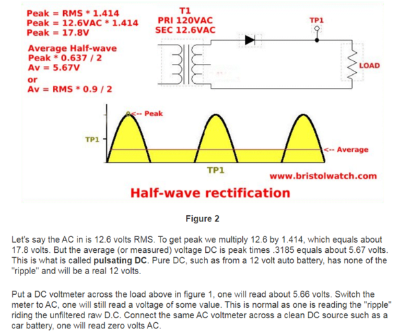
Here are some useful numbers. The value 1.414 that I mentioned earlier is multiplied by the AC RMS (root mean squared) value to give the peak voltage. The average half-wave DC voltage is determined from the peak voltage times the constant 0.637 divided by 2. Or use the VAC RMS times the value .9 / 2 which is 0.45 to figure the average. The 0.9 value comes from 1.414 times 0.637 combined.

Volts half-wave DC = Volts rms AC * 0.45

I complained that this doesn't work out to get from 18 VAC to 12.4 half-wave DC:

That doesn't work with the above 18 VAC to DC conversion. According to this, Vdc from 18 VAC (rms) would be 8.1 VDC (average). I'm not sure what to think.

Stan2004:

Well, nowhere does GRJ say his circuit is driving 20 mA into the LED.  I figure he chose a  resistor value which gives a suitable brightness.

Your relationships in your most recent post look correct.  The average voltage (as measured by a voltmeter in DC-mode) will be around 8V DC for an 18V AC (RMS) input.  This is a practical value to use for hobby purposes.  As the diagrams show, the voltage is pulsing reaching a peak of ~25V = 1.4 x 18V.  But it's also 0 half of the time.

At the peak 25V following the diode, the 470 Ohm resistor limits the 3V LED current to about 45 mA = (25V - 3V) / 470 Ohms.  But the current is also 0 half the time.  

The actual math is quite complex involving non-linear equations which themselves are just models of the underlying semiconductor physics.  There is also the issue of the voltage drop across the diode where you lose between 1/2 to 1 Volt depending on more non-linear equations.

Again, I emphasize the "practical" use of the relationships in your diagram.  So 8V (average) thru a 470 Ohm resistor into a 3V LED suggests "only" 10 mA (average) of LED current.  I suggest this is a good enough approximation for hobby work.

GunRunnerJohn:

The 470 ohm resistor was picked empirically, I made no attempt to do a "pure" calculation to get exactly 20ma average current. 

Also, I sometimes add a capacitor into the mix to eliminate flicker of the LED.  The cap typically charges to the peak voltage, so the current limiting resistor is sized to handle the peak voltage from the half-wave rectified track power.  With 18V track power, the peak voltage of the half-wave power is around 12.6 volts, so my resistor is selected to handle that voltage.  Truthfully, I simply ignore the diode drops as they're not that significant for this application.

The beauty of using LED's is it's not rocket science.  As long as you don't let the average current go over the LED's rating, you can do pretty much anything you like as far as current limiting.  I use all sorts of different current limiting values, depending on what lighting effect I'm trying to accomplish.

If you want absolute maximum brightness from your LED's without risking running them over spec, simply use DC and compute the resistor exactly.

Stan2004:

The peak voltage is 1.4 x 18V = 25V whether there's a capacitor or no capacitor.  The capacitor provides reserve energy and supplies voltage during the half cycle when there would otherwise be 0 voltage.  The practical effect is the average voltage increases from ~8V toward 25V as you increase the capacitor value.  Knowing the peak voltage is important since capacitor selection is based on the peak voltage applied.  For 18V AC track voltage, I'd use a 35V (or higher) capacitor.

As GRJ says, the capacitor smooth the pulsating voltage so that you demote visual flicker/flashing of the LED.  Teenagers can see this flicker but the typical OGR reader lost the visual ability to see this years ago...

And so that is how it has gone so far. In summary, the useful items include the following:

GRJ's numbers to run an LED from track voltage -- Diode 1N4003  Resistor 470 ohms 1/4 watt.

The ratio to obtain the half-wave DC voltage -- Volts half-wave DC = Volts rms AC * 0.45

Adding a capacitor after the diode will smooth the DC voltage but will raise it toward the peak voltage depending on the value of the capacitor used. More capacitance (higher microfarads) will raise it closer to peak voltage.

Peak voltage -- Volts rms AC * 1.414

I think that about covers it. Any exclusions from the original thread were made by me and I take full resposibility for any misinterpretations or confusion herein.

I look forward to more discussion, criticism, comments, interjections, and questions on this topic.


Last edited by Consolidated Leo
Original Post

Replies sorted oldest to newest

I have another question. Is the only difference between the various diodes that are part of the 1N4000 series the max voltage that they can handle?

I found this table on eBay:

1N4001      1A      50 Volts
1N4002      1A     100 Volts
1N4003      1A     200 Volts
1N4004      1A     400 Volts
1N4005      1A     600 Volts
1N4006      1A     800 Volts
1N4007      1A   1000 Volts

Also found this on the Vishay data sheet:
What are the important values that are relevant to how these diodes are used in our applications?

Attachments

Images (1)
  • mceclip0
Last edited by Consolidated Leo

Y'all are over-thinking this.  A LED is a "Light Emitting Diode."  If you are lighting one LED put about a 1.2K (1200) Ohm, 1 Watt resistor in line with the LED and light up your world.  No big deal.  Looks fine and lasts a long time.  I have lost count of the number of LEDs on my layout.  Running three  LEDs in series?   Use a 820 Ohm, 1/2 Watt.  Four LED's?  Use a 680 Ohm, 1/2 Watt.  No, it will not last 50 years.  No lights do.  If you absolutely cannot have a flicker, buy GunRunnerJohn's inexpensive circuit board and carry on.  This is small voltage, not rocket science.

I'm not retired from NASA, but I am a retired Electrical Engineer.

Bill: I doubt that I'll ever get all of this stuff straight in my head but I at least want to understand enough for it to make sense to me.

The numbers and the methods used to arrive at those numbers are what I'm after. If you know what's important about these issues, then you can start to play around with electrical ideas that you might come up with. And playing around is what it's all about. That's where I derive the most pleasure.

Leo,

I understand.  Your numbers are correct.  Your ideas are sound.  My point is at 18 volts, it is not critical.   I posted a knee jerk reaction to a subject that generates a lot of posts.  I invested a lot of time and money on an education that has provided me with a lucrative and adventuresome livelihood.  The ramifications were critical when building the cooling controls for Farley Nuclear plant.  Honda expected 300,000 miles of fault free instrument clusters.  But 18 volts to a scale passenger car is not in that ballpark.  You have my respect for digging deep without a campus of professors.  I mean no offense.  Here is something I put together between posts.  It is a 820 Ohm resister and three 10mm diodes at maximum voltage from a Lionel CW-80.  This is what I had at hand.  If you want to step up, full wave bridge bridge rectifiers, 600V at 3 Amps are 50 cents each.  1/2 Watt resisters are $3.00 for 20.  And a capacitor kills the flickers at about 7 cents each.  Buy some parts and have some cheap fun.

Bill

20191029_01393820191029_01401620191029_015039

Attachments

Images (3)
  • 20191029_013938
  • 20191029_014016
  • 20191029_015039
Consolidated Leo posted:

I have another question. Is the only difference between the various diodes that are part of the 1N4000 series the max voltage that they can handle?

I found this table on eBay:

1N4001      1A      50 Volts
1N4002      1A     100 Volts
1N4003      1A     200 Volts
1N4004      1A     400 Volts
1N4005      1A     600 Volts
1N4006      1A     800 Volts
1N4007      1A   1000 Volts

Yes, they're all basically the same characteristics, though I suspect without looking that the higher reverse voltage ratings may have a very slight difference in voltage drop across the junction.  I typically use 1N4003 diodes, they sufficient reverse voltage rating for most spikes that might come along.  I've seen many 1N4001 diodes in stuff, haven't seen a lot of failures.

Consolidated Leo posted:

...

The numbers and the methods used to arrive at those numbers are what I'm after. If you know what's important about these issues, then you can start to play around with electrical ideas that you might come up with. And playing around is what it's all about. That's where I derive the most pleasure.

Right!  If you aren't interested in what's going on under-the-hood just skip this thread.  But for the determined DIY'er a little additional info can go a long way.  To that end, I hooked up the circuit using a ~3V white LED, 1N4003 diode, and 470 Ohm resistor.  Power was from a Z-4000 set to 18V AC (rms).  

half wave LED scope shot 1

With ~18V AC (rms) input (GREEN trace) the half-wave diode output (ORANGE trace) is ~8V average and ~25V peak.  The LED current (RED trace) is ~13 mA average and ~45 mA peak.

half wave LED scope shot 2

The actual LED voltage (GREEN trace) is off half the time but jumps up to a narrow range around 3V.  Note the GREEN trace has a vertical scale of 2V per grid line.  The average LED voltage is 1.6V but this is an arguably useless measurement since the average includes the half of each AC cycle when the LED is simply off due to half-wave operation.  What one really wants to know or understand is the relationship between LED voltage and LED current when the LED is actually on.  It's not very insightful to say that no current flows when no voltage is applied.

half wave LED scope shot 3

Some oscilloscopes can display waveform relationships in X-Y mode; old-timers will recognize this as "Curve Tracer" mode.  So on the right display plots current vs. voltage for the waveforms on the left.  The LED is off for half the time, but ramps up and down following the hockey-stick like current vs. voltage relationship shown above on the right.  The LED turns on at about 2.5V and in this case peaks at about 3.5V when it draws about 45 mA.  Note that "x" on the curve where the LED current is 20 mA which is a popular nominal operating point.  At 20 mA this LED's voltage is about 3.2V which is as-expected for a typical white LED.

Attachments

Images (3)
  • half wave LED scope shot 1
  • half wave LED scope shot 2
  • half wave LED scope shot 3
 Is the only difference between the various diodes that are part of the 1N4000 series the max voltage that they can handle?
 
gunrunnerjohn:

Yes, they're all basically the same characteristics, though I suspect without looking that the higher reverse voltage ratings may have a very slight difference in voltage drop across the junction.  I typically use 1N4003 diodes, they sufficient reverse voltage rating for most spikes that might come along.  I've seen many 1N4001 diodes in stuff, haven't seen a lot of failures.

Thanks, John!

So the reverse voltage rating is the max amount that can be blocked by the diode in the negative (or opposite) direction. And because the voltage drops to zero in that direction, the current is blocked as well.

What about the folks on the forum who claim that you can operate an LED on AC power? As I understand it, an LED's reverse voltage is fairly low and may fail if driven too hard. I'm talking about a circuit without additional components to provide an alternate path for reverse current.


Last edited by Consolidated Leo

The folks that run LED's on AC are living on the edge.   I used to add LED's to TMCC using just the resistor and no diode.  I had a number of failures after a few months to several years, the LED would be dead.  Now, everyone knows that an LED should be good for tens of thousands of hours at least, so what was happening?  I added the protection diode, and I haven't lost one since. 

Some time back, I tested a few LED's to destruction, just to see how they failed.  The LED's in question were rated at 5V reverse voltage.  I'll admit, they would stand a lot more for a spell, but at about 13-14 volts reverse polarity, they would die within minutes.  I have no doubt that hitting them with less voltage over time would also kill them.

stan2004:

 I hooked up the circuit using a ~3V white LED, 1N4003 diode, and 470 Ohm resistor.  Power was from a Z-4000 set to 18V AC (rms).  

Way to go Stan! We can always count on you to go the extra mile to demonstrate the realities of any given situation. My hat is off to you sir! Fantastic effort!

The O-scope pictures really tell the story. I'm a bit surprised that the voltage curve (green) following the resistor has such a tombstone shape to it. I would have thought it would be much closer to the shape of the incoming current. Nevertheless, there is the half-wave cycle for all to see. The drop to zero is plainly there which accounts for the 60hz flicker that you mentioned before. Knowing about pulse width modulation and LEDs, 60hz is a much slower rate than what's used in PWM.

So are we driving the LED with too much forward voltage/current? Those peak values take it out of spec, I would think.

Last edited by Consolidated Leo
Soo Line:

So I built one....does polarity matter when powering the LED this way?

 Uhm... I started to answer this but then realized that we're in AC land. That always gets me alternating my thoughts; I think my head actually moves back and forth. But I'll try to keep typing while holding my head steady.

The cathode of the diode must point to the anode of the LED. The resistor is used to drop the current going through the LED. But since the half-wave current is uniform from the diode to the return (AC negative), the resistor can be placed on either side of the LED; the current is the same throughout.

As illustrated here, point A is full-wave AC, point B is half-wave pulsating DC. The resistor can be moved to the other side of the LED to point C; connected to the cathode of the LED.


Clearly, flipping the diode around will allow full-wave AC to pass through the LED and most likely destroy it. Flipping the LED would expose it to the reverse voltage of the half-wave DC and could also cause harm; not to mention that it would not light.

Whew! My head is spinning!

Attachments

Images (2)
  • mceclip1
  • mceclip2
Last edited by Consolidated Leo
Soo Line:

So.....does polarity matter?  I have hooked up the pictured LED set up and then reversed the leads all at 18V AC and it seems so far that it does not matter.  The LED is burning brightly either way.

Okay, I see what you're getting at. You mean the polarity of the full-wave AC input to the circuit.

No, the polarity of the leads (the 18 VAC from the transformer) does not matter. Positive and negative AC is a misnomer. They are more often refered to as AC hot and AC common (or neutral or ground). In this hobby we need to keep them straight to avoid phasing problems. That is the AC hot and AC common are 180 degrees out of phase. The hot voltage reaches a positive peak at the same time as the common voltage reaches a negative peak. If you cross them, you create a dead short.

Last edited by Consolidated Leo
Consolidated Leo posted:

...


So are we driving the LED with too much forward voltage/current? Those peak values take it out of spec, I would think.

mceclip0

As GRJ pointed out earlier, it's the average current that's relevant for any O-gauge application I can think of.  Driving the LED with 45 mA peak, but 12 mA average is not a problem.  So that's a peak to average ratio of about 4 to 1.  Consider the diode datasheet you posted.  Note that while the average current of the 1N4003 is specified as "only" 1 Amp, it can tolerate a peak current of 30 Amps (or more depending on the type of peak)… so that's 30 to 1!

A familiar LED peak-to-average example is the white LED in your smartphone.  When in "flashlight" mode the LED is driven at some average current that can be sustained for long periods.  But that same LED can be used as the camera flash where the current is briefly pulsed at a much higher level.

Attachments

Images (1)
  • mceclip0
Consolidated Leo posted:
Soo Line:

So.....does polarity matter?  I have hooked up the pictured LED set up and then reversed the leads all at 18V AC and it seems so far that it does not matter.  The LED is burning brightly either way.

Okay, I see what you're getting at. You mean the polarity of the full-wave AC input to the circuit.

No, the polarity of the leads (the 18 VAC from the transformer) does not matter. Positive and negative AC is a misnomer. They are more often refered to as AC hot and AC common (or neutral or ground). In this hobby we need to keep them straight to avoid phasing problems. That is the AC hot and AC common are 180 degrees out of phase. The hot voltage reaches a positive peak at the same time as the common voltage reaches a negative peak. If you cross them, you create a dead short.

Thanks for the response Leo.  Perhaps I did not explain myself well enough.  You answered my question.  Now onto building a dozen of these....

Dave

Regarding peak-to-average currents in O-gauge LED applications.  Every so often someone asks about converting an MTH PS2 incandescent bulb to LED (not PS3 which is already LED).  So they get out their trusty multimeter and attempt to measure the DC voltage at the lamp.  The idea being you would then use an LED calculator to select a resistor value to drive an 2V or 3V LED.

But like the half-wave example, the PS2 electronics uses pulsed DC to drive the bulbs.  Unlike the half-wave example where the LED is driven no more than 50% of the time (since it's always OFF half the time), in the PS2 lighting circuits the LED might be driven less than 10% of the time and pulsing at 1000's of times per second rather than 60 times per second if driven from AC track voltage.  This means that the peak-to-average current in a PS2 LED-conversion would be even higher than the 4-to-1 (or so) in the example shown earlier.  And like the half-wave example where one can get bogged down with equations if trying to do the math, I believe GRJ will respond to any such question with a "just use this resistor value" that I suspect was selected empirically.

Well, semi-empirically Stan.  Since the bulbs used with PS/2 are 6V bulbs, one can kinda' assume that the average voltage is around 6V.  That being the case, I selected a 220 ohm resistor for the job.  If you go by the 6V value, you could go as low as 150 with a white LED, I just added a small "fudge factor".

FWIW, the LED headlights I install are really nice and bright, and after several years of doing this for a variety of folks, I've never gotten one back for a burned out LED, so I must have been close.

Hopefully Leo doesn't mind a slight detour but I think relevant in terms of selecting LED resistors in O-gauge applications where you don't have smooth/steady DC.  So here's the PS2 headlight output voltage driving a ~3V white LED via a 220 Ohms resistor as GRJ suggests.

PS2 driving LED via 220

As mentioned, the PS2 electronics sends brief DC pulses to the incandescent bulbs.  The pulse rate is very fast - about 20,000 pulses per second in this case.  As the scope shows the pulses are ~23V DC - this was from a Z-4000 track voltage of 18V AC (rms).  

Note that if you hooked a DC meter to this headlight signal it would read only 2V DC!  This will be explained shortly.  So with these 23V pulses and a 220 Ohm resistor the peak LED current was ~80 mA with an average LED current of ~4 mA.  So here we have a peak-to-average ratio of about 20-to-1!  And as GRJ says, he's had no problems with burn-out or whatever.

But here's what's interesting.  If you didn't know what was going on under-the-hood, you might simply measure the DC voltage at the headlight socket and get a reading of 2V DC.  Then the head-scratching begins since you'd wonder what kind of a resistor could increase the DC voltage from 2V to the ~3V needed by a white LED?

So the answer is in the scope photo and the pulsed-DC nature of the PS2 lamp signals.  What you really need to measure is the RMS voltage of the headlight signal.  That's about 6V as shown in the scope measurement list.  And lo-and-behold, this is as GRJ says - PS2 lamps are 6V.  No meter I'm aware of can measure RMS of a pulsing DC voltage!  DC meters indicate the average DC voltage which is not the relevant voltage when driving a incandescent lamp with pulsed DC.  The math gets tedious with more techno-babble about pulse-modulation, duty-cycle, and the like.  So, again, for anyone but the hard-core DIY'er, you can skip the math and do as GRJ says and install a 220 Ohm (or so) resistor and you're off to the races! 

Attachments

Images (1)
  • PS2 driving LED via 220
stan2004 posted:

Hopefully Leo doesn't mind a slight detour but I think relevant in terms of selecting LED resistors in O-gauge applications where you don't have smooth/steady DC.  So here's the PS2 headlight output voltage driving a ~3V white LED via a 220 Ohms resistor as GRJ suggests.

PS2 driving LED via 220

As mentioned, the PS2 electronics sends brief DC pulses to the incandescent bulbs.  The pulse rate is very fast - about 20,000 pulses per second in this case.  As the scope shows the pulses are ~23V DC - this was from a Z-4000 track voltage of 18V AC (rms).  

Note that if you hooked a DC meter to this headlight signal it would read only 2V DC!  This will be explained shortly.  So with these 23V pulses and a 220 Ohm resistor the peak LED current was ~80 mA with an average LED current of ~4 mA.  So here we have a peak-to-average ratio of about 20-to-1!  And as GRJ says, he's had no problems with burn-out or whatever.

But here's what's interesting.  If you didn't know what was going on under-the-hood, you might simply measure the DC voltage at the headlight socket and get a reading of 2V DC.  Then the head-scratching begins since you'd wonder what kind of a resistor could increase the DC voltage from 2V to the ~3V needed by a white LED?

So the answer is in the scope photo and the pulsed-DC nature of the PS2 lamp signals.  What you really need to measure is the RMS voltage of the headlight signal.  That's about 6V as shown in the scope measurement list.  And lo-and-behold, this is as GRJ says - PS2 lamps are 6V.  No meter I'm aware of can measure RMS of a pulsing DC voltage!  DC meters indicate the average DC voltage which is not the relevant voltage when driving a incandescent lamp with pulsed DC.  The math gets tedious with more techno-babble about pulse-modulation, duty-cycle, and the like.  So, again, for anyone but the hard-core DIY'er, you can skip the math and do as GRJ says and install a 220 Ohm (or so) resistor and you're off to the races! 

As a side question to this: If you are using a PS3 steam conversion kit (on a PS1 steam locomotive) would it be possible to run all the marker/number board/firebox/cab light/the headlight lights off the headlamp circuit if they were converted to LEDs? The issue with the PS3 steam kit is that you only have remote control of the headlamp (which is a 6v bulb, not an LED) and the marker/number board/firebox/cab light have to be wired to track power. If those LEDs were instead wired to the headlamp circuit they would only come on when the locomotive is powered up vs any time track power is on. Would 7, 3mm 3V LEDs, each with a 220 ohm resistor, be able to run off the PS3 headlamp circuit without overloading it? 

Lou, you can run a ton of LED's off the incandescent headlight outputs.  They can supply at least four 60ma bulbs, so even if you consider the LED's as drawing 20ma, that's a dozen LED's off each light output.  Remember, the PS/3 steam conversion kit is a PS32 board with the stacked board that drives the LED's with the same circuit as the PS/2 boards.

I routinely run the markers (class lights), number boards, cab light, and firebox light from the headlight circuit on those upgrades.  Never ran into an issue.

Rigatoni Express Railroad posted:

Can anyone supply a part number for the 3V diode please. Not sure what size to use.  Thanks,  Joe

3V diode?  Are you talking about the LED?  They're standard white, warm white, or amber LED's, depending on the look you like for headlights.

gunrunnerjohn posted:

Lou, you can run a ton of LED's off the incandescent headlight outputs.  They can supply at least four 60ma bulbs, so even if you consider the LED's as drawing 20ma, that's a dozen LED's off each light output.  Remember, the PS/3 steam conversion kit is a PS32 board with the stacked board that drives the LED's with the same circuit as the PS/2 boards.

I routinely run the markers (class lights), number boards, cab light, and firebox light from the headlight circuit on those upgrades.  Never ran into an issue.

Oh cool. That's great to know. I've got a couple PS3 conversions I can rewire now so they stay completely dark till addressed. I assume the LED anode gets connected to the blue wire on the headlight harness correct? I believe the blue wire is hot, purple is ground.

Edit: Did some searching. Looks like the purple wire is power, blue is ground on the headlamp circuit.

Capture

mceclip0

Attachments

Images (2)
  • Capture
  • mceclip0
Last edited by Lou1985
Rigatoni Express Railroad posted:

Can anyone supply a part number for the 3V diode please. Not sure what size to use.  Thanks,  Joe

You must be asking about the LED. These can be found on Amazon, or eBay, or any number of online electronics sites. Chose a size (3mm, 5mm) a color (red, green, white, etc.). Here's a DigiKey part number: click C512A-WNN-CZ0B0152. They are inexpensive and often available as kits of different sizes or colors.

Alright! Since we've meandered into talking about LEDs, what about the charts that show that different color LEDs take slightly different voltages. And that means that the resistor values should change to match up with the color. Are these at all significant?

In O-gauge we talk about LEDs being used for track side signals and such. These are typically done with red, yellow, and green LEDs wired together so that either the anodes or cathodes are all tied together in a common conductor; common anode vs common cathode.

Sometimes, only 1 resistor is attached to the common anode for all 3 colored LEDs. So all three colors are using the same resistance and receive the same voltage. Of course the difference may be unnoticeable to humans but wouldn't you think that putting 3 resistors on the cathode side would be more appropriate?

Attachments

Images (2)
  • mceclip0
  • mceclip1

With some inexpensive 3 aspect signals from ebay I've been experimenting with, I don't notice a big difference between colors (green, yellow, red) in them. There is probably a slight difference in brightness between the 3 colors, but it looks ok to me. By the time the colors change to the next LED I don't really notice it, but others might? Signals are common anode with a built in 1k resistor. They look good to me at 12 VDC, but are rated by the seller as 12-16 volt. I tried 6, 9 and 12 volts, 6 wouldn't be bright enough for me, 9 volts might be ok for some, but I preferred 12 volts. I haven't tried them with 16 volts. 

rtr12 posted:

With some inexpensive 3 aspect signals from ebay I've been experimenting with, I don't notice a big difference between colors (green, yellow, red) in them. There is probably a slight difference in brightness between the 3 colors, but it looks ok to me. By the time the colors change to the next LED I don't really notice it, but others might? Signals are common anode with a built in 1k resistor. They look good to me at 12 VDC, but are rated by the seller as 12-16 volt. I tried 6, 9 and 12 volts, 6 wouldn't be bright enough for me, 9 volts might be ok for some, but I preferred 12 volts. I haven't tried them with 16 volts. 

Tom: Yes the "we honest" signals are built that way (common anode). But isn't the resistor outside of the signal structure and accessible for removal or other tinkering? You could then use 3 different resistors on the cathode side to tune the voltage/current for desired brightness.

With my over-bright green LEDs, I had to use a larger resistor than for the other colors just to make them look acceptably normal. But if yours look okay, I'd stick with what you've got.

You may remember this video I did with the Arduino in a test circuit using pulse width modulation (PWM). These are wired for common cathode which just goes to ground. But the anode side uses 3 separate resistors.

Attachments

Images (1)
  • mceclip0
Last edited by Consolidated Leo

It's very common to find varying brightness with cheap LED's, that's why there are very few specifications on eBay.   If you buy from major industry sources from makers that provide full specification sheets, you will know what you're getting.

I buy LED's in quantity for peanuts, and a few times I've just tossed them in a "junkbox" because of the color or brightness issues.

Yes, the we_honest signals have the one resistor on the anode wire which is accessible and can easily be removed, changed or you could also easily use separate values on the cathodes as you suggest. I am going to do some more fiddling today, but so far the built in resistor on the signals appears ok to me.

I am not sure I have seen that video? I'm off to go watch it right after this. We have been doing some similar experiments with some different circuits for operating signals, only we are using components like 555s, 556s and not micro processors.

As GRJ says above, with my cheap assortments of individual LEDs, some have been discarded due to poor or very little light, color, became sacrificial, etc. Mostly just use these for experimenting. I do have a few better ones from Digikey around here somewhere that I save for better things. 

gunrunnerjohn posted:

It's very common to find varying brightness with cheap LED's, that's why there are very few specifications on eBay.   If you buy from major industry sources from makers that provide full specification sheets, you will know what you're getting.

I buy LED's in quantity for peanuts, and a few times I've just tossed them in a "junkbox" because of the color or brightness issues.

Thanks, John! Good advice.

I wonder how companies determine what to sell as good pieces vs those that get rejected and end up sold on the cheap LED market. Is someone inspecting each one as it comes off the line? Imagine doing that all day long!

rtr12 posted:

Yes, the we_honest signals have the one resistor on the anode wire which is accessible and can easily be removed, changed or you could also easily use separate values on the cathodes as you suggest. I am going to do some more fiddling today, but so far the built in resistor on the signals appears ok to me.

I am not sure I have seen that video? I'm off to go watch it right after this. We have been doing some similar experiments with some different circuits for operating signals, only we are using components like 555s, 556s and not micro processors.

As GRJ says above, with my cheap assortments of individual LEDs, some have been discarded due to poor or very little light, color, became sacrificial, etc. Mostly just use these for experimenting. I do have a few better ones from Digikey around here somewhere that I save for better things. 

Tom: I have read with interest about you and Rod working with DipTrace on the timed signal controller. I want to use an Arduino to control the signals along with the cascading effect between each block. So it should go Red, Yellow, Flashing Yellow, then Green. I'm still working on how to do that.

The problem with the Nano is that while it's inexpensive and small, it doesn't have enough memory (RAM) to do anything substantial. I can get small things to work just fine. But then when I add in serial communications stuff, it blows up.

An object oriented language like C++ needs more dynamic memory to do anything significant. When the stack gets overrun by dynamic memory, there's nothing to tell you that it happens; until it eventually resets and starts the same thing over again. It can be very encouraging to see all the things that an Arduino can do in isolation. But when you try to put all the pieces together, boom!

For those who want to know about the "we honest" products (signals, LEDs, other modeling stuff), the direct website is wehonest.net not ".com". There is also an eBay store for "we honest", and some things are starting to appear on Amazon. I have purchased things from "evemodel" on Amazon or eBay that also include signal related products. Good stuff for the price.

Consolidated Leo posted:

The problem with the Nano is that while it's inexpensive and small, it doesn't have enough memory (RAM) to do anything substantial. I can get small things to work just fine. But then when I add in serial communications stuff, it blows up.

An object oriented language like C++ needs more dynamic memory to do anything significant. When the stack gets overrun by dynamic memory, there's nothing to tell you that it happens; until it eventually resets and starts the same thing over again. It can be very encouraging to see all the things that an Arduino can do in isolation. But when you try to put all the pieces together, boom!

Does the Arduino Mega have enough memory?   The board is a little bigger but you don't need a small board in your application.  Cost is a lot higher though at $10-20 a board.

Bob

RRDOC:

Does the Arduino Mega have enough memory?   The board is a little bigger but you don't need a small board in your application.  Cost is a lot higher though at $10-20 a board.

Bob: Yes, the Mega has more memory and is larger and more expensive. It would probably do for what I'm working on. But the ratio of RAM is still insufficient compared to the amount of program memory available.

It all boils down to the Harvard architecture that has separate program memory and SRAM for data variables. This would be great if there were more SRAM. There are some tricks to be able to access constant values and strings from program memory. But you need space in dynamic memory for any object that you create. And since the stack is also using SRAM, it can cross over into the dynamic memory area and step all over your data. The results are unpredictable.

I just need to figure out how to divide the work load on my project so that it's not too ambitious for one NANO to handle. I'll get there.

Last edited by Consolidated Leo

gunrunnerjohn:

Exactly how large an application are you talking about?

That's hard to say. Much of what happens with dynamic memory happens at run time; not compile time. So memory is allocated for objects in blocks in memory space that looks like this:

Static variables are those declared at the top of the program:

int someInteger = 0;
SomeObject object;

Dynamic memory allocation occurs when you use the "new" keyword:

myObject = new SomeObject();

The stack is setup at the high end of memory and moves downward as items are moved onto it (push). The stack pointer is what keeps this straight. When things come off the stack (pop), the stack pointer is increased to point to previously stored data.

While dynamic memory is managed to not use more than what is initially free space, the stack can grow right into the dynamic memory area and that's where the problems lie.

In addition, the static variables will decrease the amount of dynamic memory area that there is to start with. At 2048 bytes total RAM, the whole thing is pretty tight.

Attachments

Images (1)
  • mceclip1
Last edited by Consolidated Leo

Leo, Thanks, It's been a fun project and a good learning experience too. We are still experimenting.

I am still way behind in the Arduino stuff. Over my head a bit, but I have read that you can link Unos to talk to each other somehow and also share some tasks I believe. Not sure that would help. Don't know about this possibility with the Nano? You probably know more about this than I do anyway.

Have you looked at the Adafruit Metro or Metro Mini? I am not sure but they may have added things the Arduinos don't have. I think they are maybe Uno and Nano or Mini take-offs using the same processors. They are supposed to be compatible with the Adruino IDE, but I was thinking they were programmed with Adafruit's Circuit Python? Not sure maybe they work on either C or Python?

Probably not much help, just some thoughts here.

Good luck with your project and let us know how it progresses.

Edit: just saw GRJ's post above and I think the Metro's specs are quite similar to the one's he posted above, so that may not help much...

Last edited by rtr12

Add Reply

Post

OGR Publishing, Inc., 1310 Eastside Centre Ct, Suite 6, Mountain Home, AR 72653
800-980-OGRR (6477)
www.ogaugerr.com

×
×
×
×
Link copied to your clipboard.
×
×