HC-SR04 Ultrasonic Sensor
Train Detection Block Signals
I thought I share the use of this ultrasonic sensor, I was able to utilize the sensor in my outdoor dead rail layout as a train/block detection on my layout.
Since converting the Baldy & Palms Railroad to “dead rail” in early 2021, the track detection circuit on the upper loop has been functioning correctly about 80% of the time. The reed switch circuit would get triggered by the magnets at one end of the block and not at the other end. This made the circuit go out of sync. I decided to try several other sensors with the Arduino to find a suitable solution. I tried the current sensor, voltage sensor, relay circuit, and the IR sensor, none of these performed reliably.


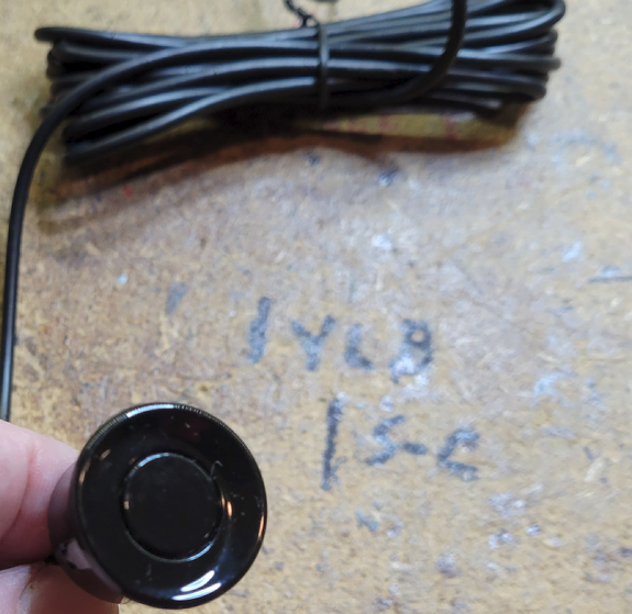
 I discovered the HC-SR04 ultrasonic sensor and decided to experiment with this sensor. I also created a better Arduino code with the HC-SR04 sensor. I adapted the HC-SR04 sensor to fit in a small signal shed to match and blend with the block signal. The Arduino code is written so the HC-SR04 monitors motion from about 4 to 8 CM across the track. When a train is detected on one end of the block, the signal will turn red, and remain red until the train exits the other end of the block, at which the signal will reset to a clear green signal. This can be used with two or three aspect signals. The code just needs a few lines of code activated. The circuit has performed very well, so I plan to incorporate this circuit in other trains detection blocks on the layout. Check out the YT video for the Arduino code sketch and circuit design. YT Video - HC-SR04 Block Signal
Hope this post helps other outdoor layouts having the same problem and eliminate the need to put magnets on locomotives and rolling stock.


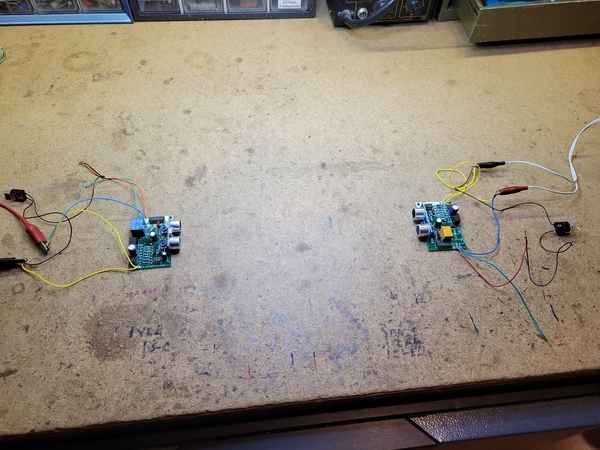


![IMG_20220227_184054[1]](https://ogrforum.ogaugerr.com/fileSendAction/fcType/0/fcOid/158251952224657396/filePointer/159237711713335270/fodoid/159237711713335266/imageType/LARGE/inlineImage/true/IMG_20220227_184054%255B1%255D.jpg "IMG_20220227_184054[1]")
![IMG_20220227_184054[1]](https://ogrforum.ogaugerr.com/fileSendAction/fcType/0/fcOid/158251952224657396/filePointer/159237711713335270/fodoid/159237711713335266/imageType/LARGE/inlineImage/true/IMG_20220227_184054%5B1%5D.jpg "IMG_20220227_184054[1]")