
Can anyone tell me what the two wire tether is transmitting between the engine and tender. The install of the EER seems fairly simple. I have to use the movement sensor instead of the axle based pulse switch that is built into the tender06B9AE09-E1CC-4362-B5FE-93F5899AA343 truck axle. And the speaker and BCR installs are fairly straight forward. I’m just not sure what to do with the tether from the engine.

Attachments

Images (1)
  • 06B9AE09-E1CC-4362-B5FE-93F5899AA343
Original Post

Replies sorted oldest to newest

Open up the locomotive and see if it's wired to the motor armature or it really has a contact.  Note that the ERR board MUST have a totally isolated chuff switch, and I really doubt that will be the case here.  If either side of the ERR RS Commander chuff is connected to frame ground, you have just toasted the board!  Let's be careful out there.

You're mixing technologies with a 30 year difference in age, you have to be sure you're following the rules.

Here's a clip from the RailSounds Commander instruction sheet in case you think I'm pulling your leg.

Attachments

Images (1)
  • mceclip0

The the EER Railsounds sound kit came with a reed switch assembly and a small magnet to trip it. There is a warning to not use the senso4vthat is on the axle of the tender.  The board, speaker and reed switch will all be mounte pd in the tender. The connections are all pretty clear. I don’t know what to do with the two wires coming Pgh from the engine itself.

Attachments

Images (3)
  • 0E884B61-DD60-46AE-A713-211D8BD2DB72
  • 0DE06BB6-298D-4F23-B9A1-A9EEBFBA7D80
  • 3A3BD5F6-38C1-47F1-8EBD-624FA2A906FF
gunrunnerjohn posted:

The ERR Sound Commander hasn't been made in many a year and is certainly not available now.  The thread pointed to is talking about the ancient Sound of Steam board, not the current version of the ERR RailSounds Commander.

Let's get our stories straight, are you talking about the wireless tether?

No, this a two wire tether that connects to the tender.

gunrunnerjohn posted:

Open up the locomotive and see if it's wired to the motor armature or it really has a contact.  Note that the ERR board MUST have a totally isolated chuff switch, and I really doubt that will be the case here.  If either side of the ERR RS Commander chuff is connected to frame ground, you have just toasted the board!  Let's be careful out there.

You're mixing technologies with a 30 year difference in age, you have to be sure you're following the rules.

Here's a clip from the RailSounds Commander instruction sheet in case you think I'm pulling your leg.

Thanks John. I read that in the manual for the sound board. I will avoid it like the plague.

If you have a pickup roller on the tender then forgo the wires coming from the locomotive.  As long as you have a pickup roller on the tender then go ahead and install your new chuff switch, wheel magnet, board and speaker in the tender.  You have everything you need make sounds from the tender without the locomotive.  Once you prove the tender is self sufficient then trim the wires in the locomotive.

In that "old" thread I provided above GGG discusses variances to this vintage with some tenders getting their own power, some from locomotive, and some with both. 

Steims posted:

If you have a pickup roller on the tender then forgo the wires coming from the locomotive.  As long as you have a pickup roller on the tender then go ahead and install your new chuff switch, wheel magnet, board and speaker in the tender.  You have everything you need make sounds from the tender without the locomotive.  Once you prove the tender is self sufficient then trim the wires in the locomotive.

In that "old" thread I provided above GGG discusses variances to this vintage with some tenders getting their own power, some from locomotive, and some with both. 

There is no pickup roller on the tender. The old board must have been getting its power from the engine. Is one of the leads controlling the smoke unit?

It appears from your photos that yellow is the hot and the white is common but let's confirm.   With your transformer powered off, set the locomotive on the track.  Take you multi-meter set to check continuity and measure resistance from the junction of the red, black and  sheathed wire on side of drive/motor to an outside rail.  If it reads less than 1 ohm then that is your common and the white at the tender is common.

Do the same for the junction on the E-unit where the tender yellow (black) connects and measure to center rail.  Should see less than 1 ohm confirming the tender yellow is hot. 


The yellow/green junction is the hot feeding the smoke unit.  The common side of smoke unit uses the chassis.  The tender is not feeding the smoke unit. 

Last edited by Steims
Steims posted:

It appears from your photos that yellow is the hot and the white is common but let's confirm.   With your transformer powered off, set the locomotive on the track.  Take you multi-meter set to check continuity and measure resistance from the junction of the red, black and  sheathed wire on side of drive/motor to an outside rail.  If it reads less than 1 ohm then that is your common and the white at the tender is common.

Do the same for the junction on the E-unit where the tender yellow (black) connects and measure to center rail.  Should see less than 1 ohm confirming the tender yellow is hot. 


The yellow/green junction is the hot feeding the smoke unit.  The common side of smoke unit uses the chassis.  The tender is not feeding the smoke unit. 

Thank you! It’s never going to run as well as my MTH engines, but it sure sounds better!

I also forgot to mention that I am powering the track, that it is running on, through the VAR1 output on my MTH TIU. I was also powering the switches through the same old ZW transformer. I have since powered the switches with a separate power source. The engine runs better but it needs 10 volts to run at a constant speed around the oval. I also tried powering that oval directly with a smaller Lionel transformer. It runs well at a lower voltage.

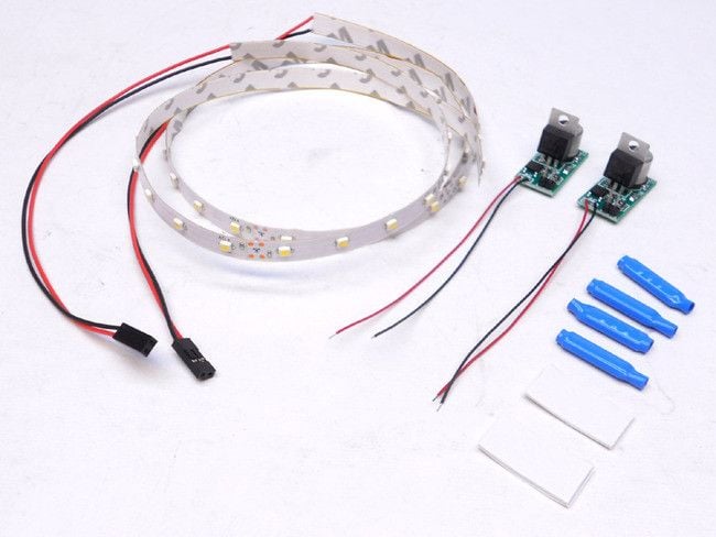
Now, I’m faced with the decision to convert the lighting in the passenger cars to LEDs or quit investing more money in the train. 

I also learned something about these old MPC era Hudsons. The sound board, in the tender, is glued in place on top of a piece of foam rubber. The foam has deteriorated over the years and may be making contact with the metal chassis. I have cleaned it up and used a different material on one of mine. I have a second one that had the same issue. 

gunrunnerjohn posted:

Well, my kit on Henning's is half that, a kit does two cars. Passenger Car LED Lighting Kit

If you don't mine a little soldering, you can do them for half of that, maybe $11 a car using the LED regulator modules and a reel of LED's.

LED Lighting Regulator

I’m going to do the light conversion in all six cars. Just for=the fun of it, I popped the tops of three of the cars.  What I found was a piece of cardboard shoved up into the roof to block light from being visible through the roof. They aren’t secure except by friction. Should I paint the upper part of the plastic and pitch the cardboard? And does it matter if I mount the LEDs on the roof or the floor?

Attachments

Images (1)
  • 5DA9C9BC-2CAF-4D73-837E-A1DEF470D8EE
George Mason posted:
gunrunnerjohn posted:

Well, my kit on Henning's is half that, a kit does two cars. Passenger Car LED Lighting Kit

If you don't mine a little soldering, you can do them for half of that, maybe $11 a car using the LED regulator modules and a reel of LED's.

LED Lighting Regulator

I’m going to do the light conversion in all six cars. Just for=the fun of it, I popped the tops of three of the cars.  What I found was a piece of cardboard shoved up into the roof to block light from being visible through the roof. They aren’t secure except by friction. Should I paint the upper part of the plastic and pitch the cardboard? And does it matter if I mount the LEDs on the roof or the floor?

What are the blue things in your photo of the kit?

George Mason posted:

I’m going to do the light conversion in all six cars. Just for=the fun of it, I popped the tops of three of the cars.  What I found was a piece of cardboard shoved up into the roof to block light from being visible through the roof. They aren’t secure except by friction. Should I paint the upper part of the plastic and pitch the cardboard? And does it matter if I mount the LEDs on the roof or the floor?

I'd probably paint the plastic and pitch the cardboard.  I like the light coming from the top, though with silhouettes I suspect it won't make much difference.

George Mason posted:

What are the blue things in your photo of the kit?

Those are solderless "bean" splices.  The kit was designed to allow installation in standard passenger cars with no soldering.  Of course, having that extra stuff, not to mention adding the connectors and wires, runs up the price of the job.  That's why I recommend the regulators for anyone that can solder a few wires.  You'll end up with probably a neater job and spend half the money.

gunrunnerjohn posted:
George Mason posted:

I’m going to do the light conversion in all six cars. Just for=the fun of it, I popped the tops of three of the cars.  What I found was a piece of cardboard shoved up into the roof to block light from being visible through the roof. They aren’t secure except by friction. Should I paint the upper part of the plastic and pitch the cardboard? And does it matter if I mount the LEDs on the roof or the floor?

I'd probably paint the plastic and pitch the cardboard.  I like the light coming from the top, though with silhouettes I suspect it won't make much difference.

George Mason posted:

What are the blue things in your photo of the kit?

Those are solderless "bean" splices.  The kit was designed to allow installation in standard passenger cars with no soldering.  Of course, having that extra stuff, not to mention adding the connectors and wires, runs up the price of the job.  That's why I recommend the regulators for anyone that can solder a few wires.  You'll end up with probably a neater job and spend half the money.

Thanks for the good advice. I have no problems with soldering. I’ll be ordering everything today and hopefully be started on the project next week! It’s good to be retired!

Add Reply

Post

OGR Publishing, Inc., 1310 Eastside Centre Ct, Suite 6, Mountain Home, AR 72653
800-980-OGRR (6477)
www.ogaugerr.com

×
×
×
×
Link copied to your clipboard.
×
×