I'll be honest. I'm an absolute electrical moron. I can put a few leads to the track via a terminal block but beyond that, I'm out. Feel free to snicker at this post all you want. 

In short, I want to wire a toggle switch to be able to turn off several sidings on my layout. I decided to do the upper loop as an experiment before doing more. 

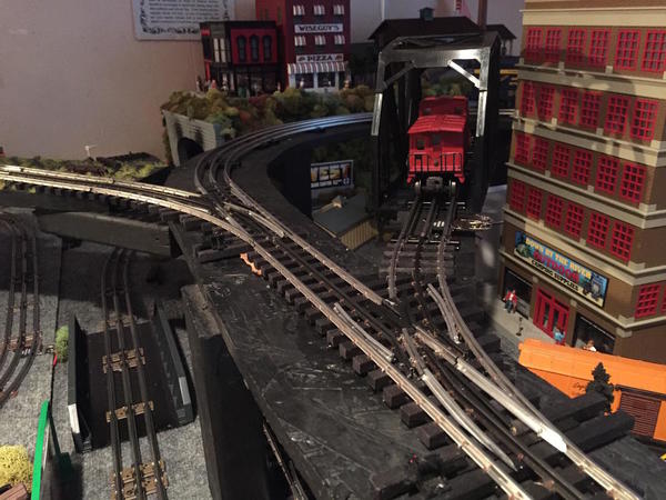
Here are the two sidings I was hoping to wire to one, 3 position toggle. 

IMG_5082-2

Here is said toggle switch. Center position is "off" and both up and down are on (or Hi/Lo)IMG_5081-2

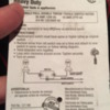
Here is said package on the switch and wiring diagram. Seems simple enough, right? Apparently wrong!

IMG_5080-2


So, can I wire what I have to turn off/on each siding individually? I was able to get one siding to turn on and off if totally isolated. Once track is re-connected to the loop, it is powered all the time and the switch makes no change. Pulling the center track pins are no help. 

Can anyone please help me with a dirt simple set of instructions or wiring diagram? Thought this would be a bit easier! 

Thank you!

Attachments

Images (3)
  • IMG_5082-2
  • IMG_5081-2
  • IMG_5080-2
Original Post

Replies sorted oldest to newest

Hopefully this helps...  You should be switching the power (AC Hot) which should be going to the center rail.  So transformer post A for instance on a Lionel ZW should be wired to the center terminal on the switch.  The outer contacts on the On-Off-On switch should be wired directly to the center rail of the siding, spur or block that you are trying to turn on or off with the switch...  It sounds like you neglected to put an insulating pin, (plastic) or at least have a 1/16 inch gap in the center rail of the track, between the main and the siding or spur....  If you don't do this the main line power will flow into the siding track, as soon as you push the track together,  and the toggle switch is meaningless...  

Also, not over complicate, but it helps to understand the bare minimum about AC track power....   The A, B, C, D terminals on transformers are putting out AC hot  ( 0 - approx. 20 Volts AC ),  the return path for the electricity is the  AC Common, on most transformers, it's labeled common...  The AC only powers the trains engine and lights when the circuit is completed.... So when you move your toggle switch to the OFF position, you're breaking, or "opening" the AC hot line.    

Again, hope this helps more than it hurts.  

For two sidings on one switch all you need is a double pole single throw switch. Or in other words a basic on-off switch with 2 sets of on off contacts. The switch you have is a single pole double throw that switches back and forth between two different items (light bulbs per the wiring diagram), or powers one item with two different sources of power. 

I have all my sidings/spurs wired with separate switches, one per siding/spur. If that would be ok for your needs then it's just a matter of getting some basic on-off switches and breaking the power to the center rail of the desired siding or spur. I suppose if you wanted to control 2 sidings from one switch that a basic on-off switch could still be used by connecting the power to one terminal and the two center rails to the other terminal of the switch. This would depend on switch amp rating and load on the two tracks combined.

Edit: The links I added are for reference only because they had different views of the switches. If you decide which way you want to go we can fine them for much less cost, I think.

Last edited by rtr12

I don't feel like you got the right toggle switch.. You just need a basic on/off switch, one for each siding.  A  Atlas selector could be used, it has provision for three sidings you can control from it by just sliding a button, I believe they are black with yellow sliding switches.  Or you could get a single pole, single throw toggle switch.  Both do the same...

Marty

It's the right switch if you want to power just one of the two sidings at a time. Either siding X or siding Y. As "STEIMS" said above, the power from the transformer goes to the middle terminal. A wire runs from each of the switched terminals (the ones at the ends) to each of the isolated sidings. Isolated in the electrical sense means that the outer rails are metallically continuous with the rest of the layout, but the center rails are insulated where they join the main line, at the track switches (turnouts.)

Add Reply

Post

OGR Publishing, Inc., 1310 Eastside Centre Ct, Suite 6, Mountain Home, AR 72653
800-980-OGRR (6477)
www.ogaugerr.com

×
×
×
×
Link copied to your clipboard.
×
×