Hi guys,

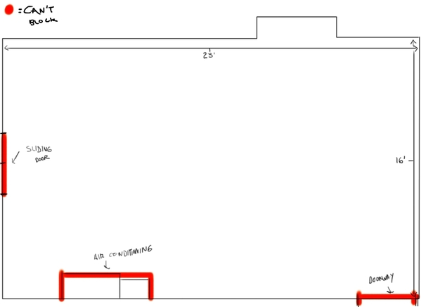
I am thinking of building a layout soon. I have measured the room in the basement, and it is 22' 6" x 15' 4", with an air-conditioning unit measuring at 24" x 37" offset towards the sliding door at the back wall. I would like to build a 'Folded Dogbone' track layout, but I need help with designing a track plan.

Thanks for the help,

Alex

  • A minimum curve of O-72, so I can run larger engines/rolling stock
  • If possible, a two-track mainline
  • A passenger station
  • Tunnel or a bridge
  • Maybe a couple of sidings for some factories, etc.

Room

Attachments

Images (1)
  • Room
Original Post

Replies sorted oldest to newest

@ogaugenut posted:

A little more information would be helpful. 

What track system will you be using?

What is the notch in the top wall?  How deep is it? How wide?  How far from corner?

How far is the sir conditioner from the corner?

How wide are the doors?  How much room between the sliding door and the top and bottom walls?

Hi,

I have some measurements for the notch, air conditioner, sliding door, etc.

  • The notch is about 6' across and 2' 5" deep, and is offset about 3' from the corner. I plan to put shelving for my trains in that area.
  • The sliding door is 6' 6" across and offset 5' 5" from one of the corners. I couldn't reach the other corner at the moment but I think it is roughly 3 1/2 feet from the other wall.
  • The air conditioner is offset 16' 4" from the furthest wall and about 3' 1" (?) from the sliding door
  • The doorway is 39" across and offset to the far end on the wall, furthest from the sliding door
  • I am thinking of using Atlas.


Last edited by Lionel2056

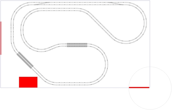
I made some refinements to the original design.  The maximum curve is O99 now.  I've dded some industrial sidings and a small yard.  To keep Rich happy, there is a yard lead.  There are reversing loops incorporated into the inner loop.  I only used #5s and O72s so there shouldn't be any restrictions on what engines you operate.Lionel2056 V2

Jan

Attachments

Images (1)
  • Lionel2056 V2
Files (1)

The bridge area is approximately 2 feet wide and would be hinged.  The crossover that starts on the bridge could be moved to the top thus preserving the two reverse loops.

I figure that the left (lower) side of the sliding door opens so one still has access.  The A/C has access room and the siding if built could be made removable.

Jan

@Jan posted:

I made some refinements to the original design.  The maximum curve is O99 now.  I've dded some industrial sidings and a small yard.  To keep Rich happy, there is a yard lead.  There are reversing loops incorporated into the inner loop.  I only used #5s and O72s so there shouldn't be any restrictions on what engines you operate.Lionel2056 V2

Jan

I like the configuration.

Please forgive me if you've already thought of this, but mentioning it just in case...

When providing access to the A/C (or any other equipment), be sure to include room to maneuver a replacement into place when the time comes.  I've seen some layouts where a furnace replacement will require the use of a sawzall on the layout.  Ouch.

I would build the sidings by the A/C for easy removal if necessary, but one could crawl under to change the filter.  Also, I assumed that entry to the room was through the door on the lower right.

A thought on the "bridge" section is that because of its size and weight a swiveling, rolling table might be ideal.  Several Forumites have described them in other threads.

Jan

Add Reply

Post
The Track Planning and Layout Design Forum is sponsored by

AN OGR FORUM CHARTER SPONSOR

OGR Publishing, Inc., 1310 Eastside Centre Ct, Suite 6, Mountain Home, AR 72653
800-980-OGRR (6477)
www.ogaugerr.com

×
×
×
×
Link copied to your clipboard.
×
×