
Finally started on the layout! But first, following your recommendations, I painted portions of the backdrop. I guess I am more of a carpenter than a painter, but it this will do for now. A couple of shots before starting the fun part.


A new leg design so the frame rests on the legs instead of on the screws that fasten the leg to the frame. (BTW - I just noticed that the camera distorts some of the images - the legs ARE SQUARE to the frame when done!)


Saturday:
Assembling one of the cross braces –


An afternoon’s worth of work - how it looked Saturday night (12' x 12' section):


A now to continue . . .

Alex

Last edited by Ingeniero No1
Original Post

Replies sorted oldest to newest

Hmmm...obviously not modeling Missouri...no trees on them thar hills.

Benchwork and backdrop look very nice. I like substantial bench work...makes you confident that the wood will not "sag" over years and that it will support the weight of the scenery and track.

It looks like that could be a long reach in some places, so I am sure you have something figured out to address that...access hatch, small child that will crawl out and rerail your cars, a system of overhead rails, cable and a harness so you can fly over the layout...something like that last one would be really cool.
Aex

Your benchwork is just fine and so is your backdrop artwork. You did a very credible job with the backdrop.Dont forget to drill the holes in the framework so you can route the wires through the frame and let it support the wiring.

Your leg design is very interesting. I dont think any of us consider how the forces are distributed when supporting the layout and attaching the legs.

How high are you making the benchwork?

Looking forward to your progress.
Greg:
” Are you planning a hatch to access the areas closer to the wall or are you just figuring you can climb up on top of the layout if necessary?”

There will indeed be access hatches. They will be the kind that lift up and will be supported by telescoping tubes so I can lift them up and swing them out of the way as necessary. But I will also climb on top for track laying, etc.

Bruce:
” I appreceate your background painting as well…”

That’s something I have a lot to learn, and my wife will be helping as well. One thing I found: Home Depot sells 8-oz containers of ANY Behr mix paint they offer (over 4000) for $2.94. They call them Interior/Exterior Paint Testers, and they are great for this.

Tony:
” Hmmm...obviously not modeling Missouri...no trees on them thar hills.”

That is correct; mostly west. For now, the railroad is the UPSF, or Union Pacific - Santa Fe merger, which exists is my fantasy world.

Owen:
” add some haziness to simulate distance…”

Precisely what my wife and I have been pondering. I tried spraying it lightly with grey primer paint, but that didn’t work. I wonder if there is some sort of opaque coating, almost clear, as may be used to protect painting drawings, etc., and that doesn’t smell too strong.

Rich:
instead of drilling holes through the bench work.

I may use those as well. The portion that you see above, which is about 1/6 of the layout, already has 140 Ø3/4” holes! What a pile of shavings!

Thank you all for your ideas and comments. I will keep posting progress.

Alex
Hey Patrick!

(Background painting is quite a learning process - thanks!)

The top of the frame is 47”, and when I add the 5/8” plywood and 1/2" QuietBrace, it will be just over 48”. I have tried different heights, starting at 36” and up to 44” which was my last layout – my first O-Gauge. (BTW, I am 5’11”)

The reason is to make it easier to get under it. My back is not what it used to be, and I like to be able to sit on a short stool to do wiring without banging my head. (I have no hair left on top of my head to tell me that a 1x4 or 2x4 is in close proximity Smile) Also, the perspective for viewing the details is better in most cases. But since you cannot see the whole layout or get a birds-eye view, I will have a couple of platforms, about one foot high, from which to see the layout.

The main level will be 48”, the second level 57” and the “EL” train will be at 66”. My wife says that while standing on the floor, the “EL” train will appear to her as the real thing – she will have to look up to it. There is a lower level up front that will be 25” high, but that will be a gorge for my long trestle. I should finish this portion tonight or tomorrow night, depending on what time I get home from work, and I’ll post some pictures. BTW, I got that idea from you! (Hope you don’t mind.)


Thanks!!
Alex
I am the same height. I like the height in some areas, But what has me a little disappointed is my front section is mostly 44" where i was going to put the town but i couldnt see past the first row of buildings .
When i work my way around to it I am going to lower the town section back down to 32"(the laterials are there luckily).

Since your at this point ,just wanted to point out you might want some low and high sections.

I get the back thing. LOL. benchwork Looks great!!
I do try to do something everyday, and the weekends are great!

With the new frame just completed this weekend, I am about 40% of the overall frame. It is going along well, and although I was planning on adding some plywood and QuietBrace to the partially finished frame, I feel like completing all of the frame and then going to the plywood stage.

Here is a picture of part of the finished are as seen standing on the floor.


This is what it looks like from a platform 18” above floor level, as my Control Center will be. I will be able to see most of the part shown, and if I look to the left, I will be able to see all of the other (60%) portion.


Thanks for looking!

Alex
" wish I lived closer.."
Well, when you come to St. Louis next time, just send me an email and we'll get together!

Made some more progress last weekend. I finished the third, largest, and last section of the framing for the lower level, and started painting some buildings (more time consuming that mountains!).

As seen from looking south west, standing on the floor.


Birdseye view (standing on 18” high platform) looking south east.


What you see under the frame are the two carts I had built to move the drywall and other construction material around while I was finishing the basement. Now I use them to store the train stuff. I can easily roll them out when I need t get a box or work under the layout, and roll them back in when done. We will keep them to store boxes and other things, and will ‘hide’ them with a curtain or something when they are under the layout.

Carts out:


Carts back under:


I'll post a few more details tonight.

Thanks for your comments and looking.

Alex
Wow! This is great! Your benchwork construction is nothing short of perfect! I already find myself anxious to see what you've done next. I really like what you done with the storage carts on the casters. My guys always say if there's a way to use more space then Ill find it. Well those storage carts are right up my alley. Anyway.... looking fantastic. Please keep us posted.
Watching the construction of your layout is part of a learning experience for me as I have not started mine yet.
The consideration for the bald head and stiff back are well noted because I also share those traits.

I really like your idea of resting everything on the top of the support post instead of hanging on the side.
Thank you for taking the time to show your progress.
Yes, the carts are working even better than we expected.

Glad to share what I am doing.

I finally made one of the several hatches I will need. This one is 14 x 18 inches, and although it is OK, the next one will be 14 x 20 inches. I used a Ø1” closet rod that I had, and it works well. Also, I will space the two supports further apart, perhaps 3 inches instead of just 1-1/2 for better stability. As they are they hold the hatch fine, but when raising it and lowering, it vibrates somewhat, and I hope further apart spacing will help.

The pictures should show what I did, but if you have any questions, p-lease let me know – I also have drawings.

The hatch lowered, in place.


The hatch raised and turned or swung.


Birds-eye view.


Underneath – hatch lowered.


Support detail.


Support with hatch raised.


Will have more pictures tomorrow.

Thx for looking.

Alex
Tom *, Ray – Thanks!

For the second hatch, I added an additional, third support and consequently increased the distance the tube is supported. This not necessary, and I will cut off the added third support. It protrudes another 3” under the layout, and doesn’t really make it better. Two supports as for first hatch works just fine.

The second hatch under the yellow building. The first one is marked with a blue ‘X”, as I do not want to test its strength when working on top.


The second hatch raised. The tube is shorter than I used for the first hatch, and it is better; I can work on the top of the hatch itself this way.


Another view of the hatch raised.


Now I am working on the first graded track, 0 to 9” at 2% or slightly less. Be back soon. . .

Alex

(*) Tom, not long ago you asked about QuietBrace. That is what I am using, and you can see some of the double track roadbed I have cut so far.
Tom,
Even though more expensive, I probably would have used Homasote if I had found it around here since it is what I used for years; but the QuietBrace is working fine.

One thing I am doing differently is not using another track bed over the QB. I had always used cork track bed over Homasote over plywood for my HO layouts, but in retrospect, I can't imagine that those trains really needed that much sound-deadening measures!

The O-Gauge layout I had for a couple of years (until last year) was Fastrack over QB, over plywood. I thought that the noise was minimal and I did not mind it at all. On the few occasions when I ran the trains with no engine sounds, it reminded me of the HO trains - really quiet - and I did not like it as much.

So this time it will be the Atlas track over QB over plywood. I will still cover most of the layout with QB, even if there are no tracks, as it is easier to drive small nails, ‘plant’ trees, carve grooves, etc., in it than it is in plywood; same as I used to do with Homasote.

Alex
Hey Jeff,

The first hatch was 14" x 18" and although I could turn around easily when standing on a stool 10" or 16" high, it was difficult when standing on the floor. So I made the second hatch 14" x 20" and did the trick. Wink
(BTW, I am 5'11" and 180 lb.)

I am continuing with the 5/8" plywood top on the first level so I can get started on the supports for the second level. The 5/8" plywood is working fine, and it should please those who think that 3/4" is too much as well as those who prefer something heavier than 3/8" or 1/2" Big Grin

Be back soon -

Thx!

Alex
Last edited by Ingeniero No1
Thank you Jeff! They do the trick in some areas.

Patrick: And I will have a yellow road leading to the basement!

Progress Report -

Added some plywood, cut first of two graded track spacers, cut QuietBrace for first curved graded track and a straight section, started city backdrop –

Plywood is almost done:


Grade spacers in 1/8” increments to be place every 6” under the QuietBrace (QB). That’s 1/4"/foot or about a 2% grade. Going up to 9” high.


Cut one sheet of QB for the first graded curve and some straight sections. Drew lines on the QB for the inner and outer diameter cuts as well as the inner and outer track centerlines. Even though I am using sectional track here, I prefer to have the centerline as a double-check.


Testing the spacers.


The double main.


Trying my hand at painting buildings for a city. This is a lot harder than mountains!


Be back soon, and thank you for looking.

Alex
Greg: Planning is much easier now with RR-Track and CAD. I still have some of my old (25-40 years old) HO layout plans drawn on the drawings board – paper and pencil and lots of eraser for editing - that was a challenge. What I find now is that we are more likely to make more changes, since it is so easy. I am on the 25th iteration of the track!

I start out with just the track; upper and lower levels separate, design the frame for them, and then superimpose the frame on an image of the RR-Track rendition. For example, here is an image of just the track, color coded, and then the same image with the CAD drawn frame on it:


Thanks, bmac, I will do.

Alex
Thank you, Patrick, Alex. It is because of the examples we have the privilege to see here on the forum, starting with your very own work, that we discover that we may be able to do things that we had not suspected. In other words, we attempt to imitate the works that we admire.

I’ll do the best I can. I do want to get the basic layout, track, and controls done as soon as possible so I that can run the trains. After that, I can take my time with the scenery and the other items that are not essential for the operation of the trains.

Thanks!

Alex
Progress is somewhat slow, but not for lack of trying. The way I designed the layout requires a lot of cut straight and curved track sections, and I am spending quite a bit of time with the cutoff wheel and the file. Anyway, here are some pictures.

Some of the track at Etieca Valley as seen when standing on an 18” platform.


Track that will connect the West and East sides.


City Backdrop: I paint some every week end, but I find this somewhat difficult.


This portion of track will be supported by a wooden trestle. It will span nine feet, with a 30” bridge under the straight track section. I will build the trestle from scratch and will post pictures soon.


Track gauges, as posted by Don (DMASSO). These are great and really help lay track easily and accurately. I made one for three tracks and two for two tracks, as shown, and have been using them with great results.


To join Ross Custom switches to the Atlas track, I simply cutoff one end of the standard Atlas track joiner so it is flush instead of having the protruding lower end. This allows the joiner to engage more of the RCS rail.


Back soon, and thank you for looking!

Alex
Jack,

As follow up to Don's reply -
I used a 60-tooth, thin kerf Freud blade (10" table saw). The slots are a slip-fit (snug) on the rails, so you have to get the distances just right. You can use an 1/8" kerf blade, I imagine, and have a little looser fit, and it wouldn't hurt.

I used 4-1/2" center distance since that is my curve spacings (Ø108-Ø99), but you can make your gauges to fit your spacing, as Don mentioned above.

Alex
It has been a while since my last update, but I have been making some progress. Besides track laying, I also upgraded my DCS TIU’s to the latest software, and even ran some trains! I had a new MTH F3 ABA Santa Fe and passenger car set, and also an MTH Big Boy that I had received for my birthday and Christmas and had never run. They are fantastic!

Anyway, I am about done with the lower level track; just need to do one section that will not take long. Here are some pictures that you may enjoy.

My wife and my granddaughter just before I started laying track at this end.


I found that the RR-Track layouts are very precise and if the tracks are cut and laid accurately, they will match the RR-Track perfectly. One of the tricks is to establish the proper radius for the curves. Even when using sectional track as I am using, if the centers are not established, the tracks can be off considerably. Here are some examples from this last track laying session.

My granddaughter took this picture standing on a stool while I was checking some curves.


Other centers:


Trying my hand at painting clouds of the stormy variety.


The tracks that connects the two main areas.


Bird’s Eye views


My now favorite way of connecting the wires to the track (extremely easy to do)


Overall at Eye Level


I’ll be back soon with more pictures. Thank you for looking!

Alex
Alex,

Looks great so far! Keep the updates coming!

I was wondering how you like your decision to go with the ross switches and the Atlas track. I just started ordering Atlas track, and am still up in the air over the switches. I guess the only reason not to use Ross, would be because the ties look so much larger than on the Atlas track? What were your thoughts on that?

Also you posted above "My now favorite way of connecting wires to track." What exactly are you doing there?

Keep up the great work!
Zett,

No problem installing or mating the Ross switches with the Atlas track or switches. Here are some examples using plastic rail joiners and also the regular Atlas joiners. When using the latter, I cut off about 1/8” from one end of the joiner with the cut off wheel because the exposed Ross switch rails are short. But the joiners fit just perfectly of the Ross rails.


My concern is that none the DZ machines have worked as I would expect – at least not yet. I test every Atlas and Ross switch before installing them, and so far none of the over 30 Atlas switches I have used so far has malfunctioned.

But not a single one of the eight Ross switches I have used up to now (all curved, BTW) has worked as I think they should. The switches themselves (without the DZ machines) are fine – they operate freely. But the machine does not throw all the way consistently even when not on the switch! That is, instead of traveling fully (from one end of the crescent shaped slot to the other) they are shy about 1/16 to 1/8 inch. I have tried 14v and 20v, and the result is the same. I have also added two or three drops of fine oil as has been recommended, but that has not helped so far.

As far as my favorite way of connecting the wires to the rails, for the full story look at this thread:"Screw It!" – but you can get the idea with these three pictures:


After trying several #0 sheet metal screws, (Button Socket Head, Slotted Pan Head, and Phillips Pan Head) I have settled on the #0 x 1/4" Pan Head Phillips Sheet Metal Screw, Black Oxide.

Thank you for looking.

Patrick. Am I excited yet? You got that right! When I finally ran a train last week, even though it was only over 40 or 50 feet of track, I was beyond myself. Thanks!

Alex
Here is my wiring scheme (track power only) as of now – it will change!
• Two Z4000’s to two TIU’s. (12 AWG wires. Two about 100-ft, two about 400-ft)
• TIU’s fixed and variable inputs jumpered to provide four output channel s.
• Four output channels from each TIU to four terminal blocks for a total of eight terminal blocks. (14 AWG wires, each about 20-ft long) Some of these will be relay controlled to cut power off to selected track blocks.
• Eight terminal blocks power up to six track blocks. (16 AWG wires, each about 12-ft long)

The wiring diagram:


The track layout


Alex
Last edited by Ingeniero No1
Don,

I mounted (late last night) the TIU's pretty close to where they are shown in the wiring diagram. Looking at the RR-Track layout, TIU No. 1 is just under the small bridge over the lake above the "Madera Heights" name, and TIU No. 2 just to the right of the word "Aisle" on the right of "Villa de Rocas".

The two Z4000's will be where [CONTROLS] is, at the bottom of the diagram, to the left of "Etieca Valley".

I hope to install a couple of terminal blocks tonight, but I am making these with terminal strips that I had from previous HO layouts and is taking a little time. Also, I can find only two of the magic bulbs of the 10 I bought three years ago, so I just had to order some more. (Well, at least I won't be moving again and misplacing things.)

And Thanks again.


Alex
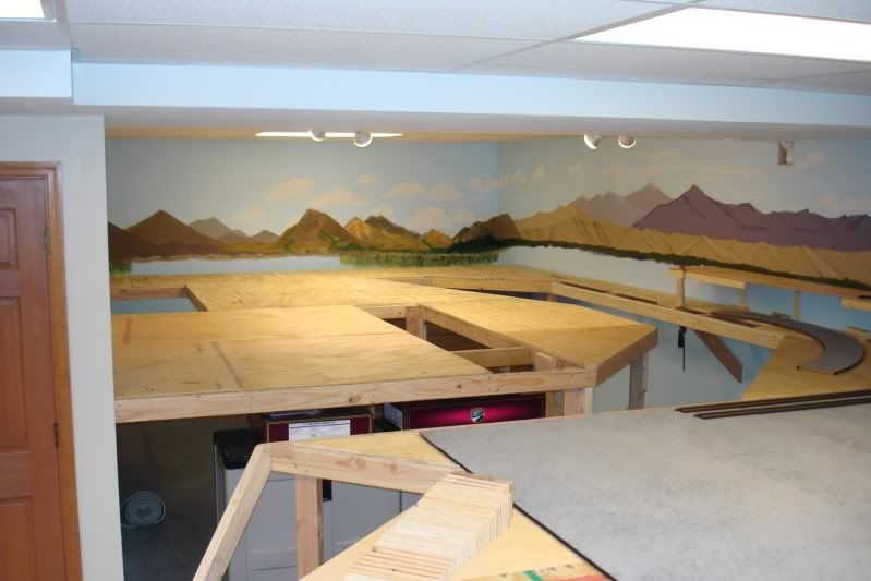
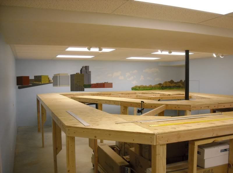
It has been a while since I update my progress, but believe me – I have been working on my layout!

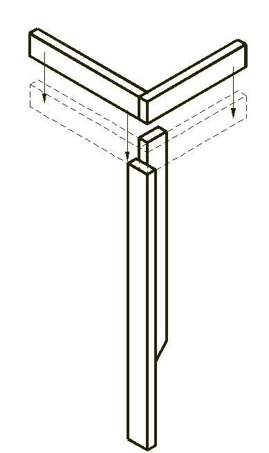
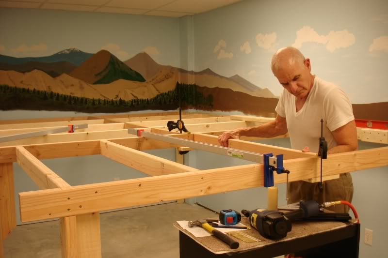
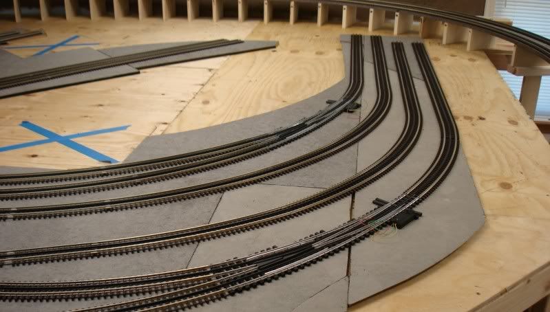
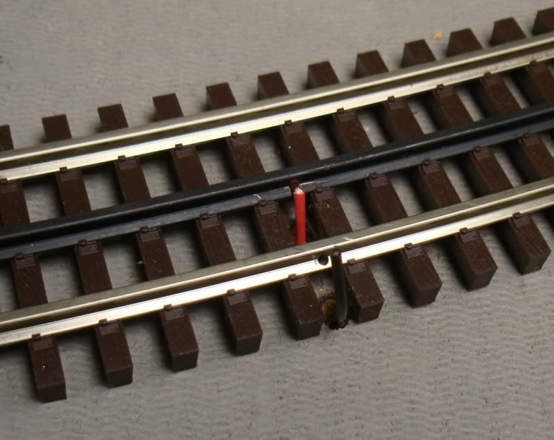
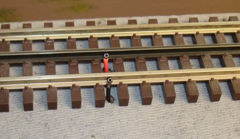
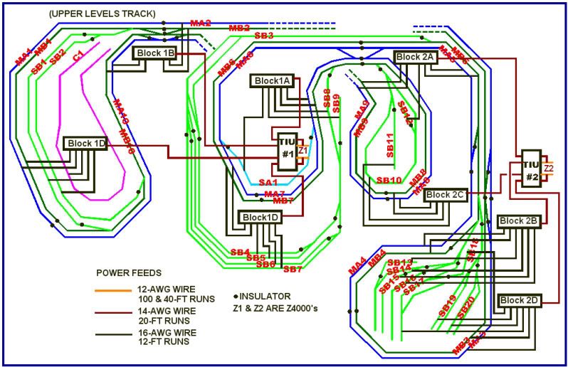
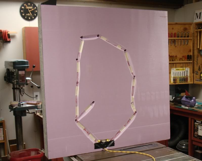
I worked on the DCS system for a few days, laid more track, and then started on the trestle. Since I could not find the type of prebuilt bents I wanted, I decided to go from scratch. I downloaded a lot of information on full-scale as well as model trestle design, and came up with what I wanted.

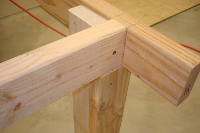
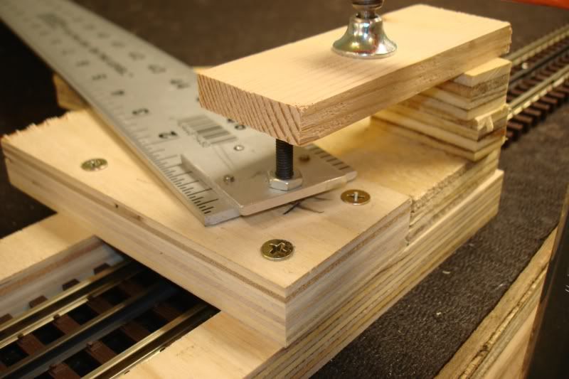
Instead of buying all the ‘lumber’ already to size, I cut my own 1/4-inch square pieces from 6-inch wide x 24-inch and 36-inch long poplar stock from HD and Lowe’s. The smaller stuff is Midwest basswood that I bought from Tower Hobbies.

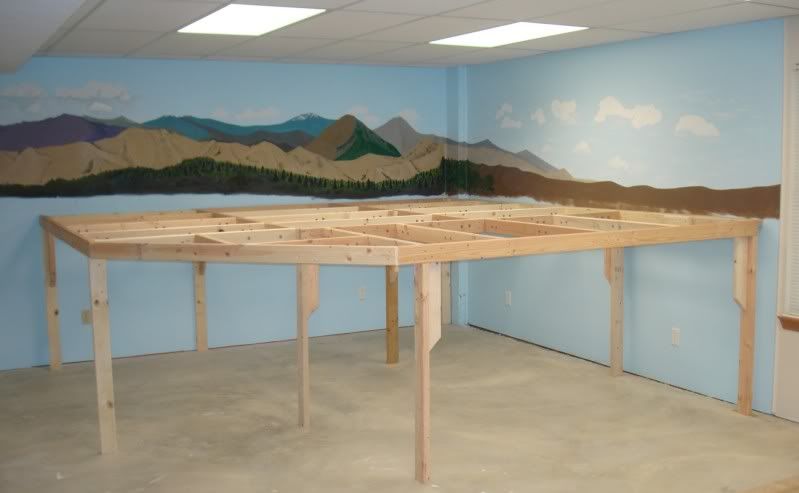
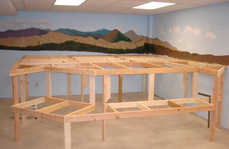
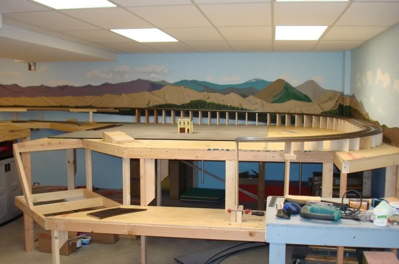
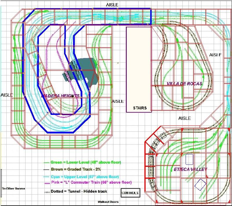
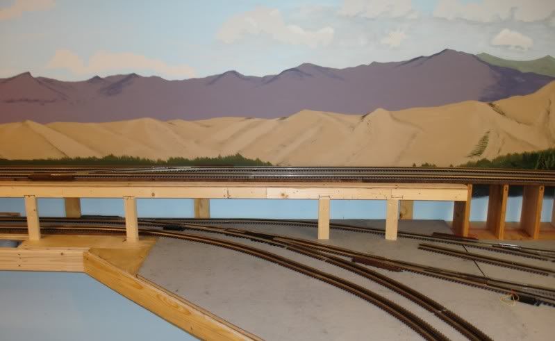
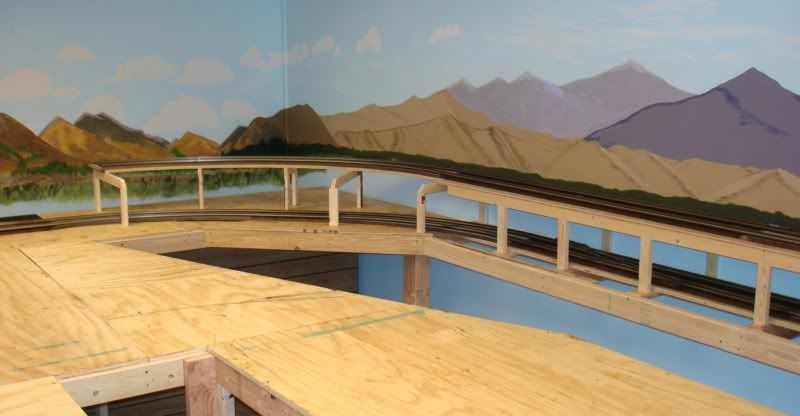
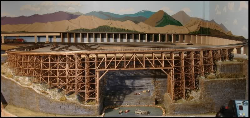
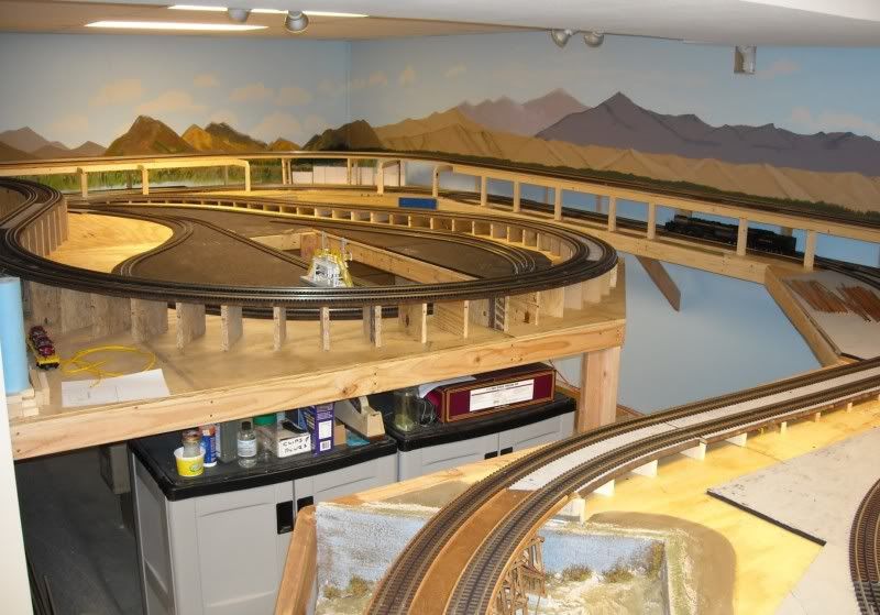
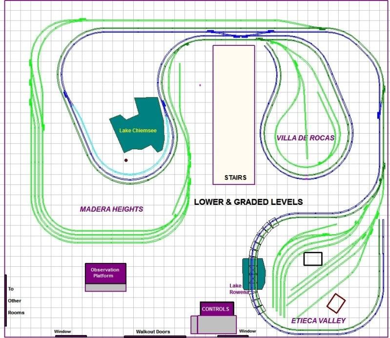
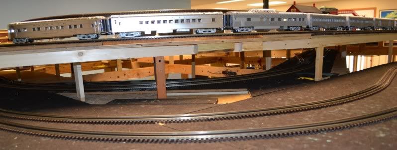
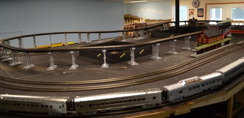
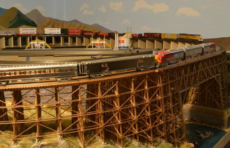
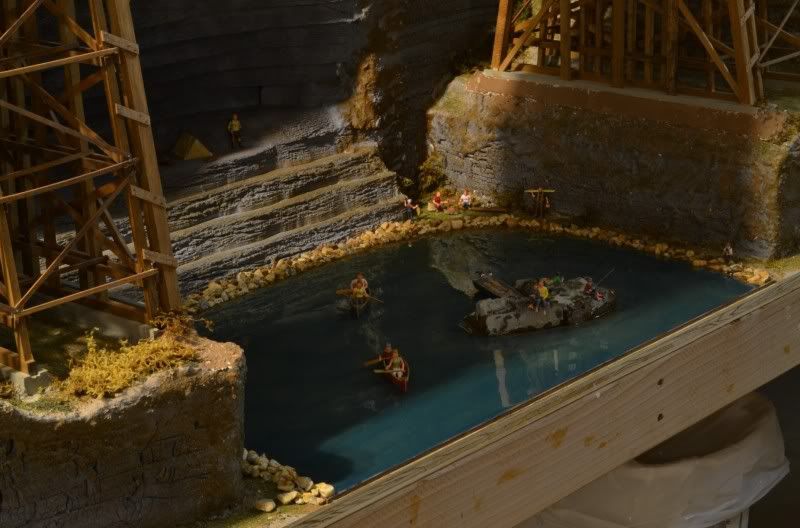
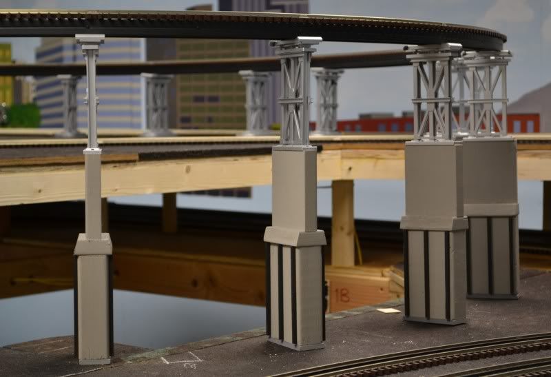
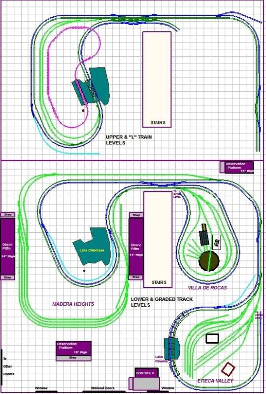
The Judy Jane Trestle at Etieca Gorge over Lake Rowena is 10-feet 4-inches long (496’ FS), its average height over the lake is 25-7/8 inches and it is on a 2% grade. It supports the dual-main track, and will consist of 29 bents ranging in height from 4-13/16 to 19-9/16 inches. Each bent has 10, 1/4-inch square posts (12” square FS) of varying lengths, and a number of horizontal (sill) and diagonal (sway) bracing depending on height. The mud sills are 1/4 x 3/8-inch as I have grooved the piers 1/8-inch for better stability and alignment, so they will protrude 1/4-inch and appear to be 1/4-inch square.

The center portion of the bridge, over the lake, will not have bents that extend to the ground. Instead, those bents will be 6-1/4 inches long and rest upon heavier lumber.

After much deliberating and reading, I decided to make the sway braces out of 1/16 x 1/4-inch (basswood), as many full-scale trestles use this size (3” x 12”) lumber. Other lumber will be 1/8-inch square (6” x 6” FS) and 1/16 x 3/16-inch (3” x 9” FS). Altogether there will be around 2,000 sticks.

I have all the bents finished except I ran out of ‘lumber’ for the sway braces for the last 12 bents; the shorter ones. I will finish them this week. My wife Judy, after who I named the trestle, stained all the ‘sticks’ and has built a handful of bents. I’ll post specific details of construction soon.

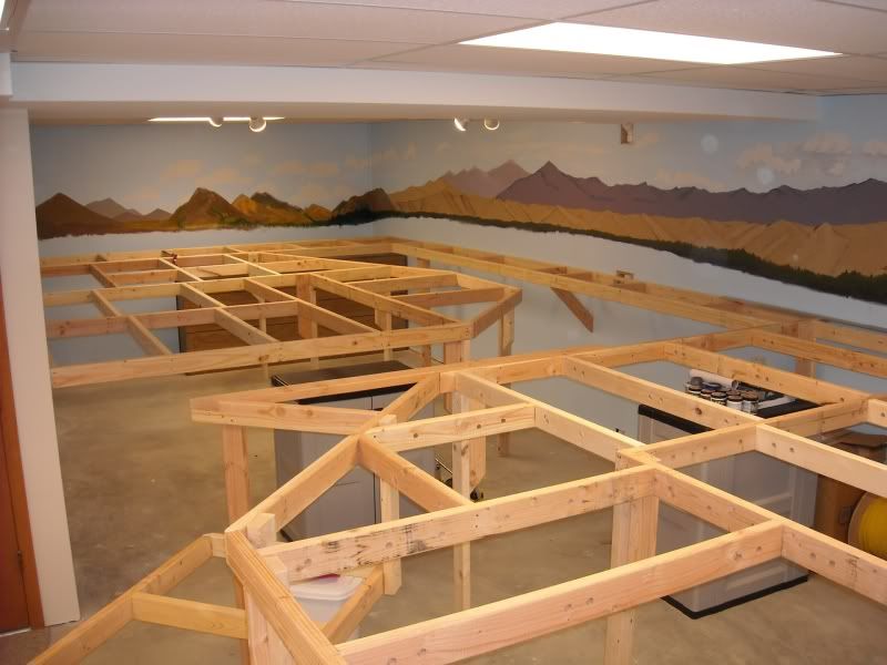
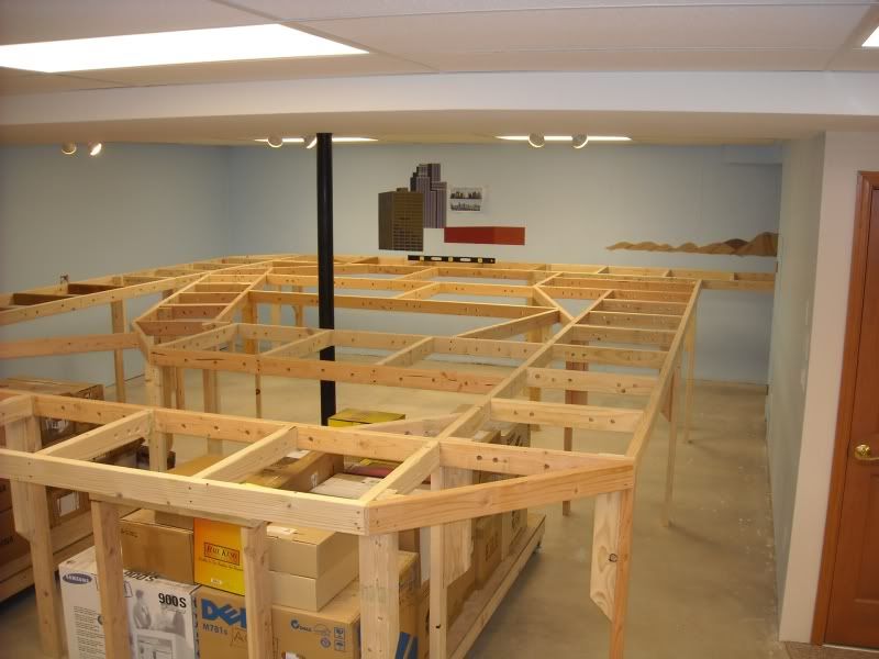
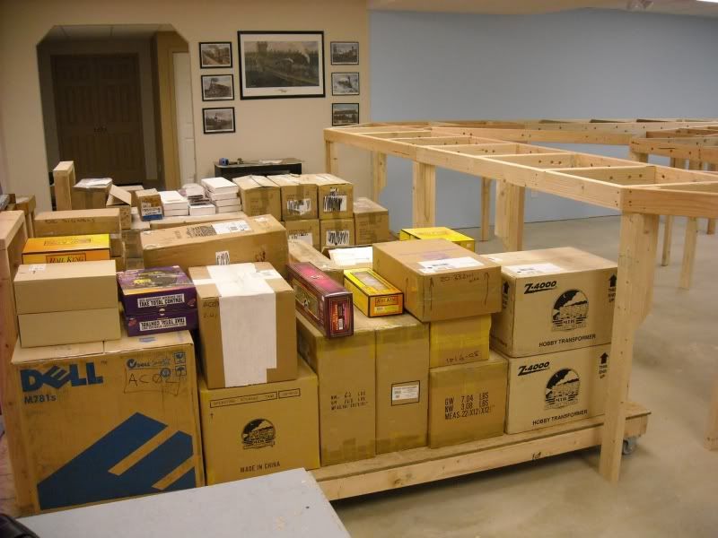
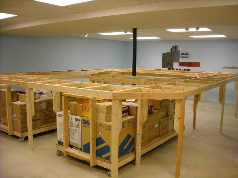
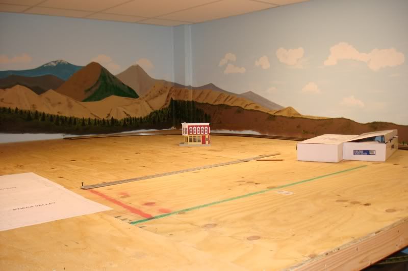
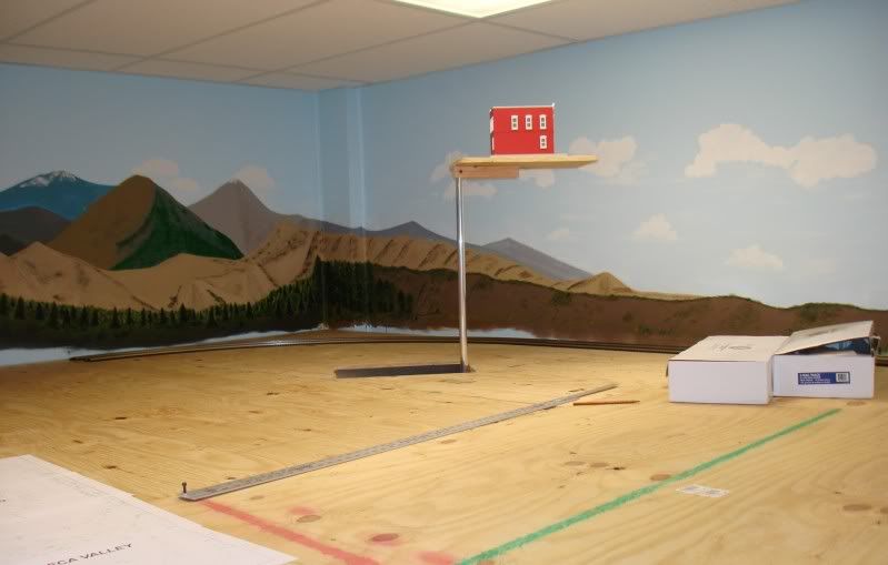
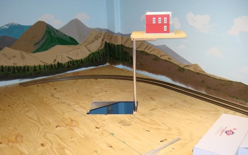
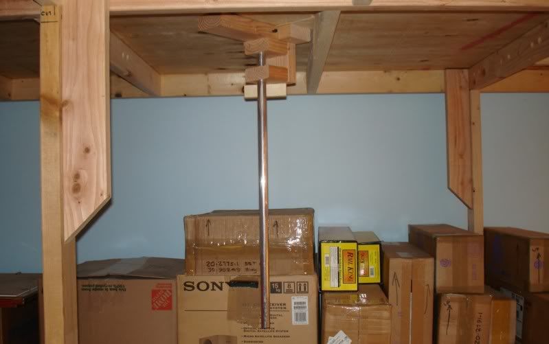
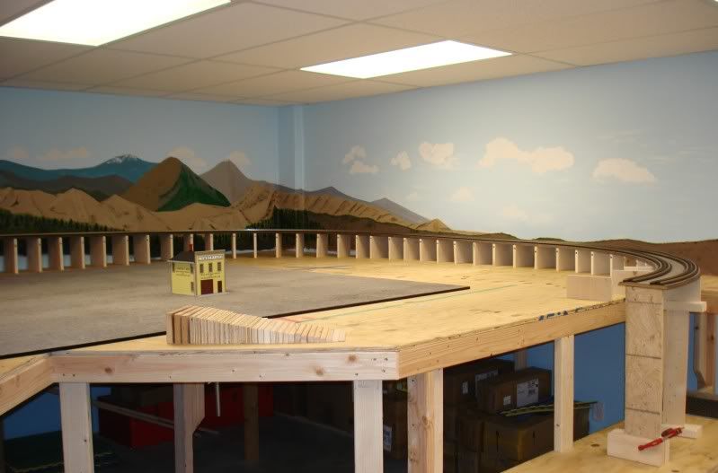
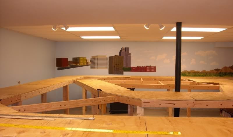
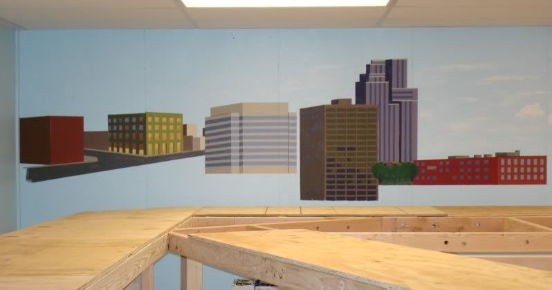
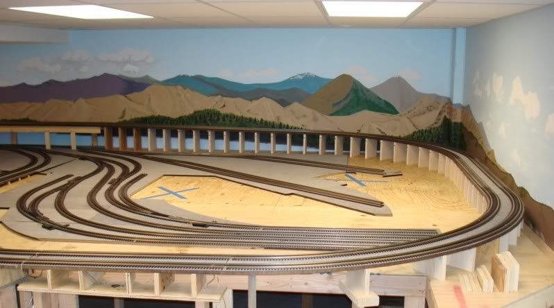
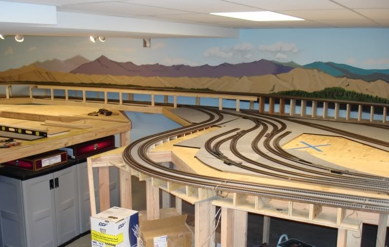
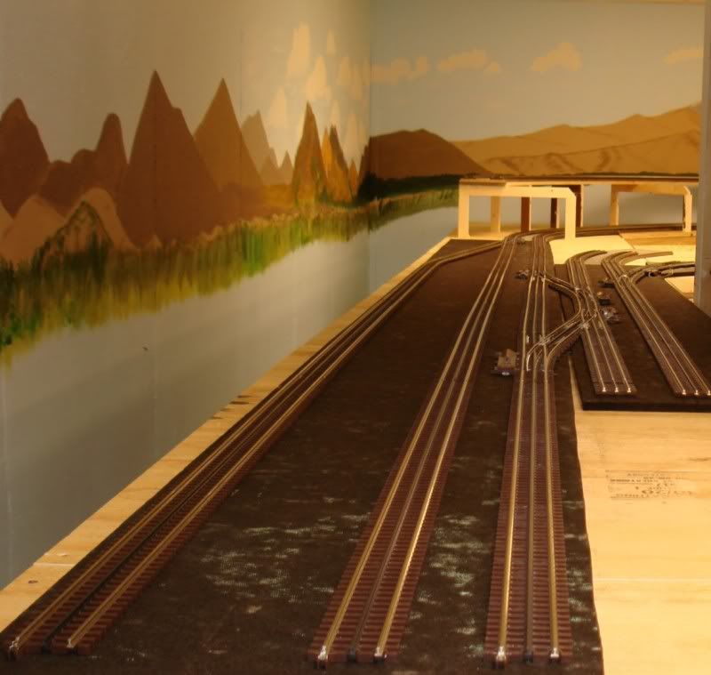
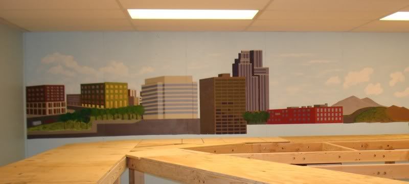
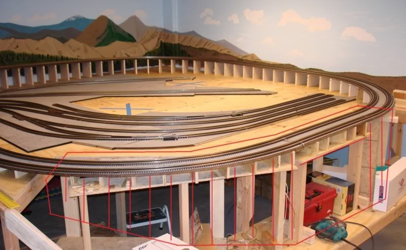
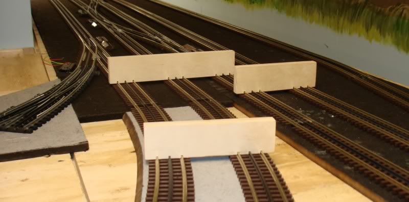
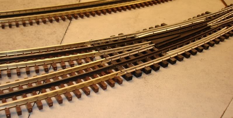
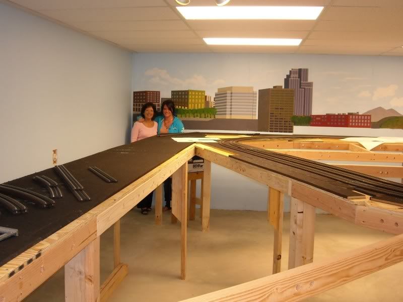
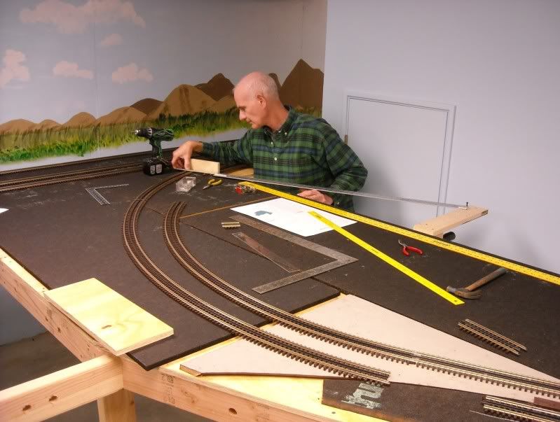
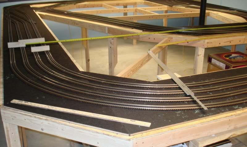
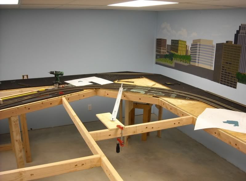
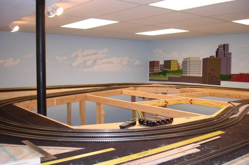
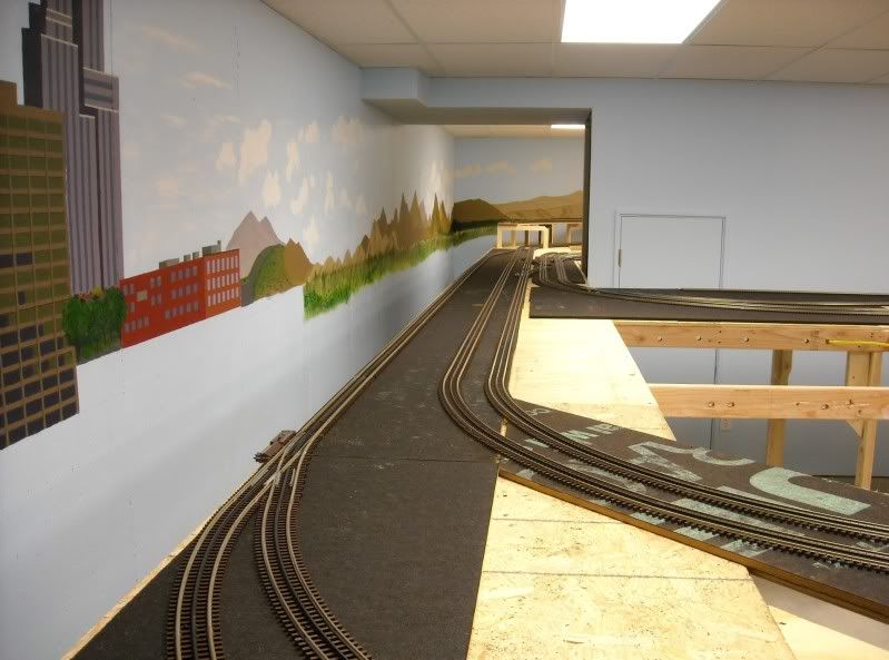
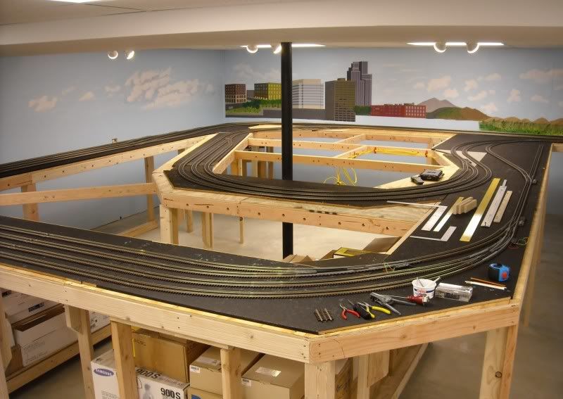
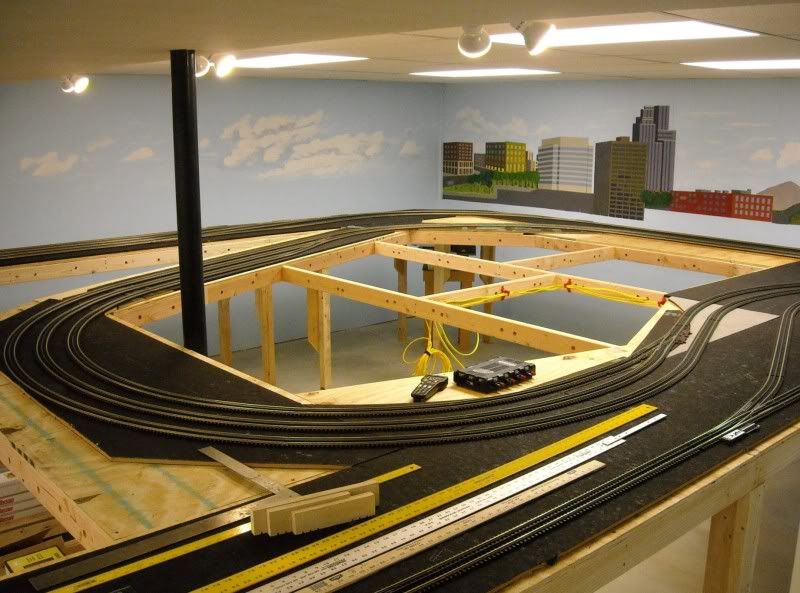
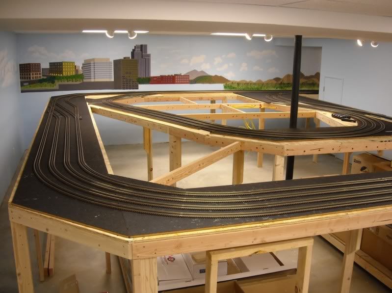
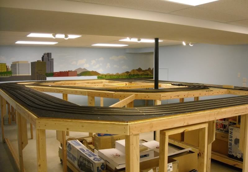
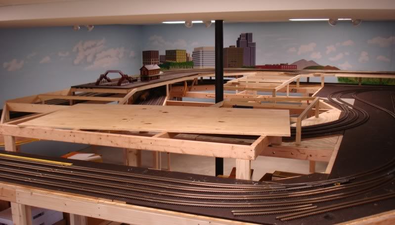
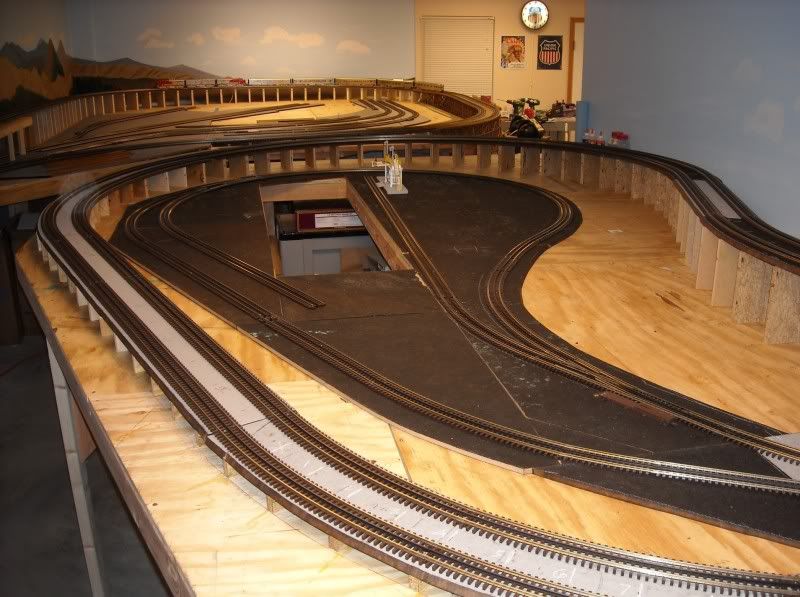
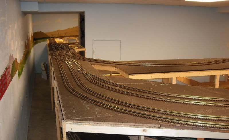
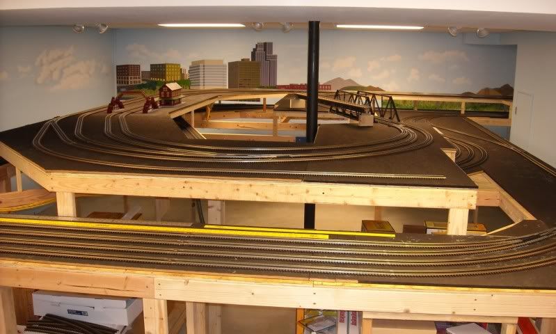
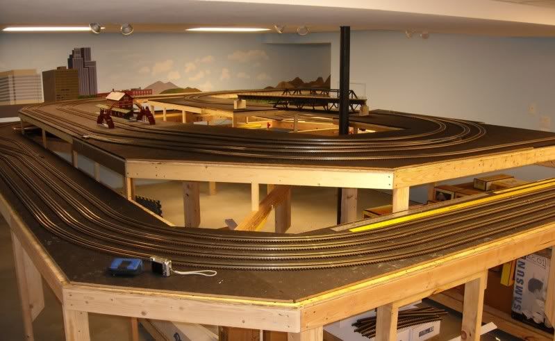
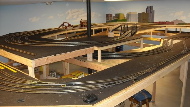
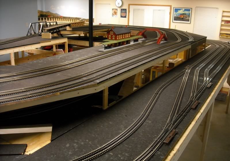
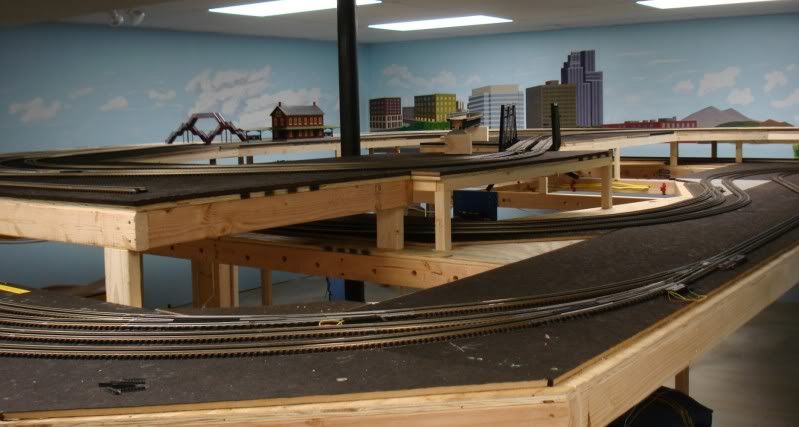
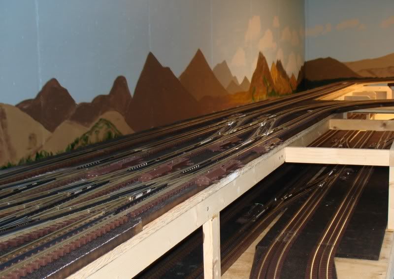
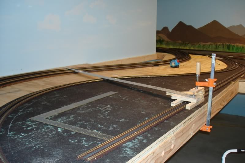
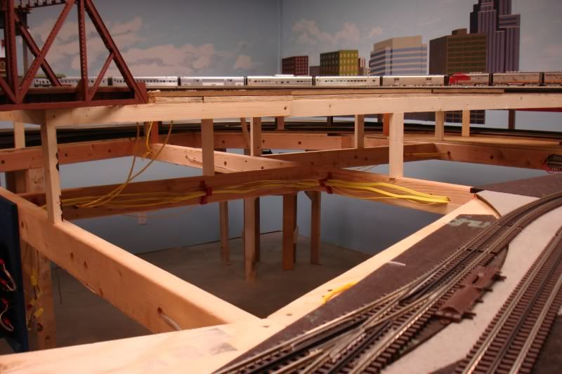
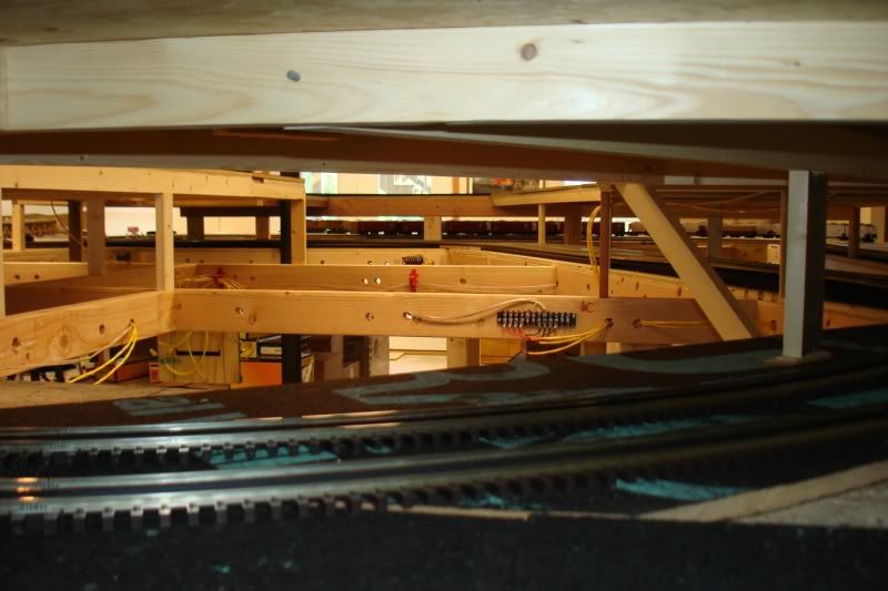
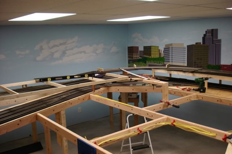
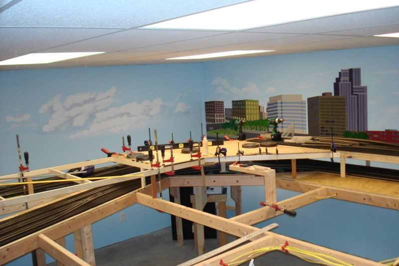
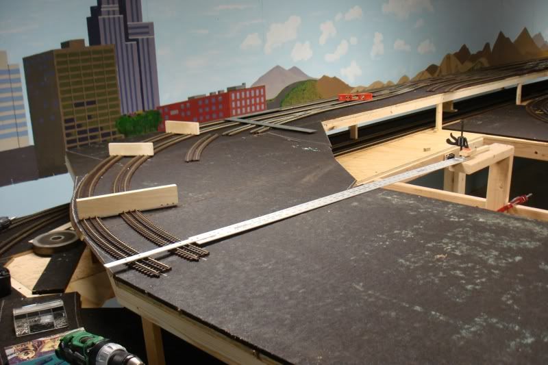
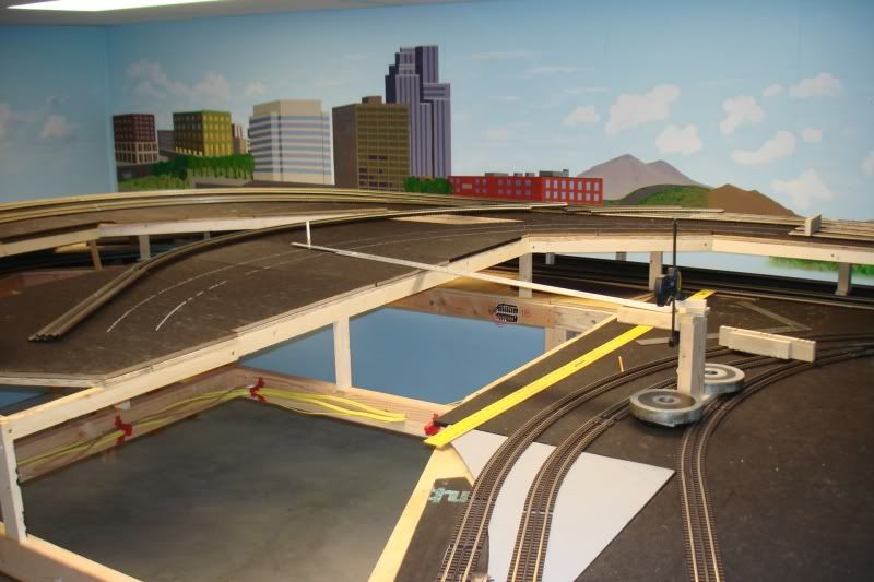
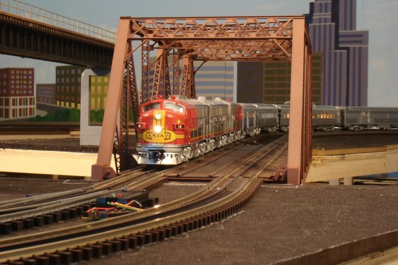
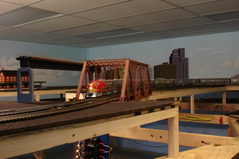
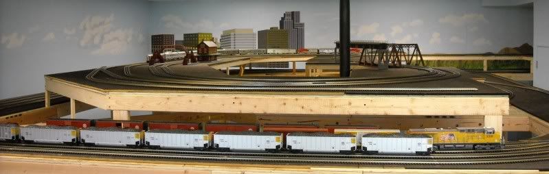
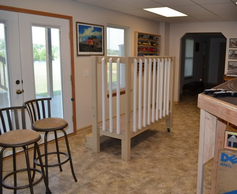
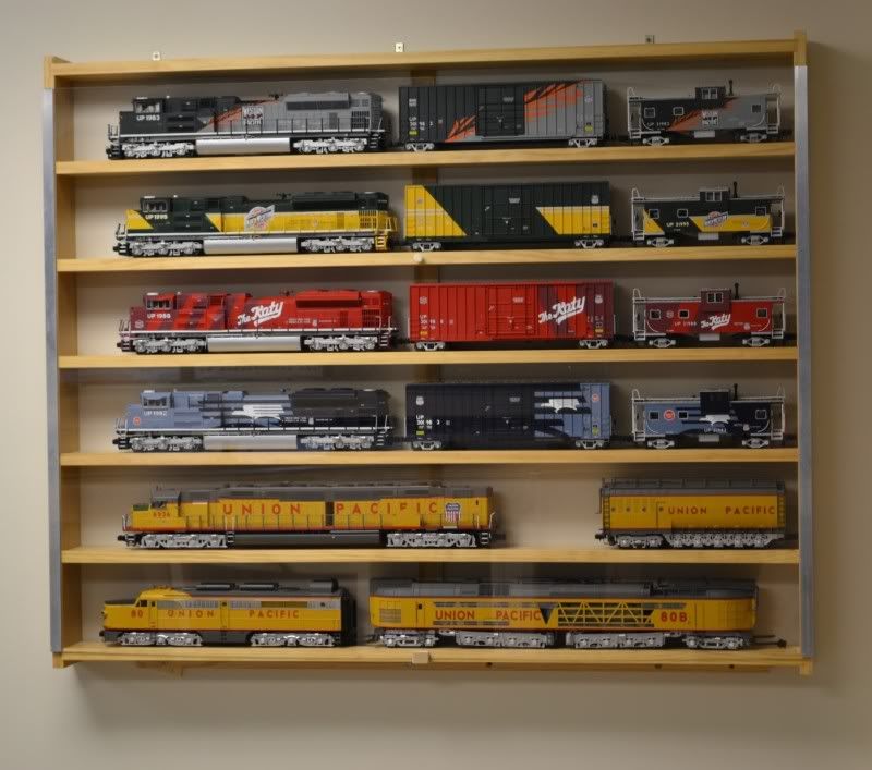
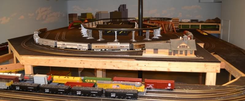
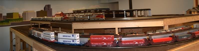
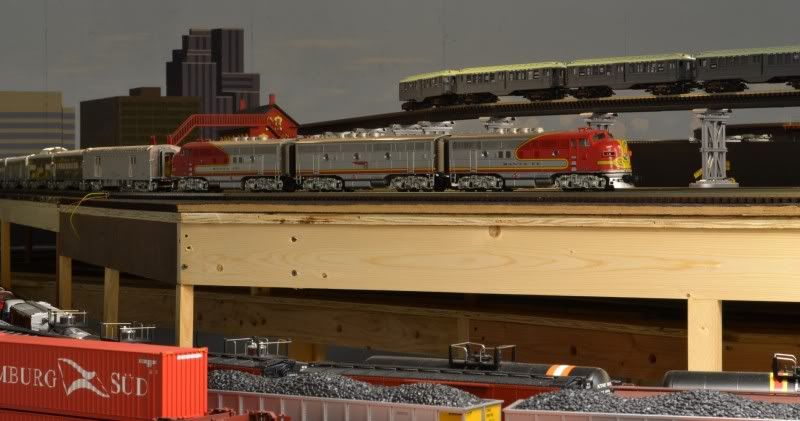
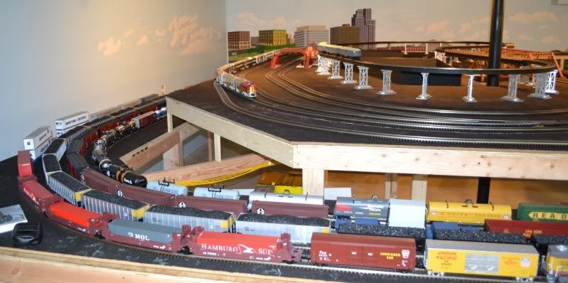
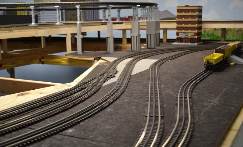
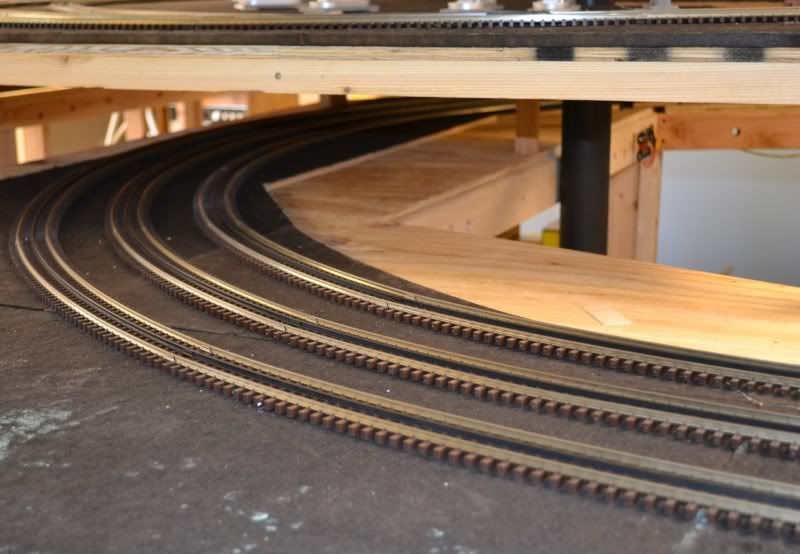
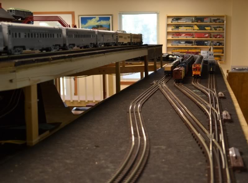
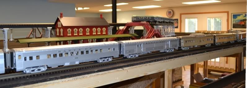
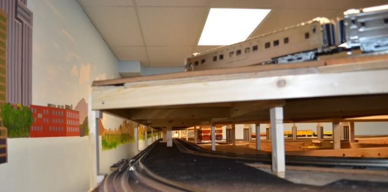
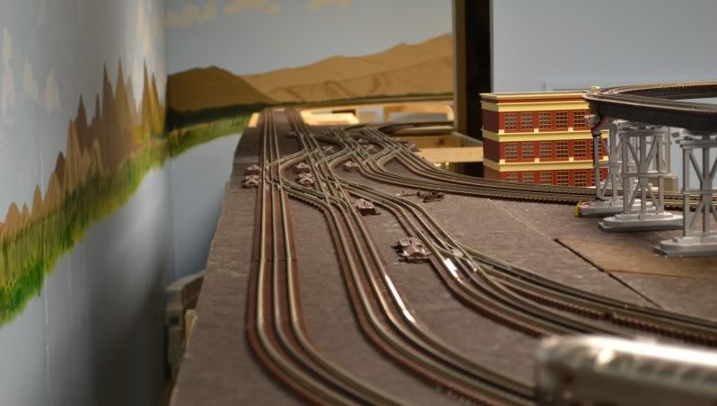
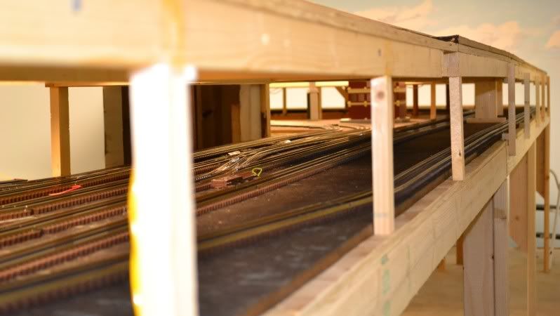
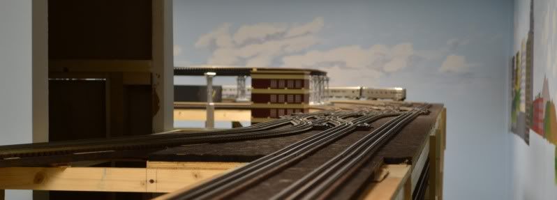
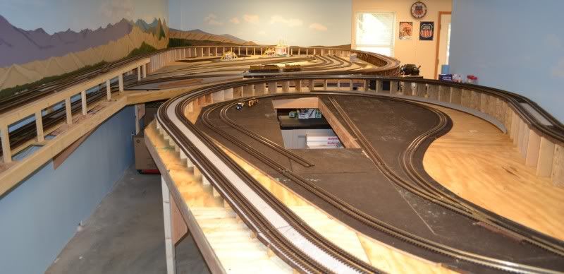
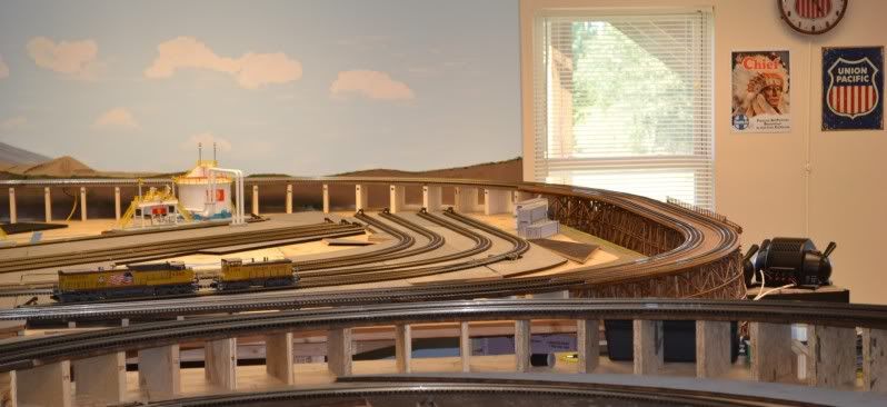
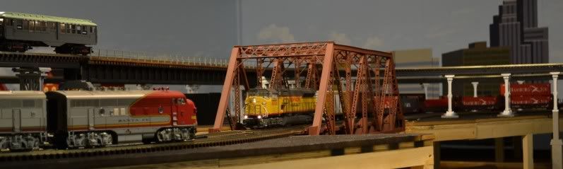
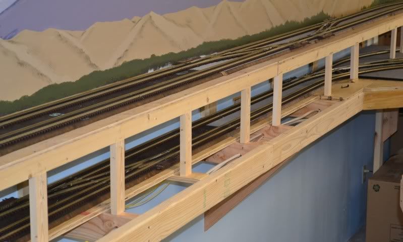
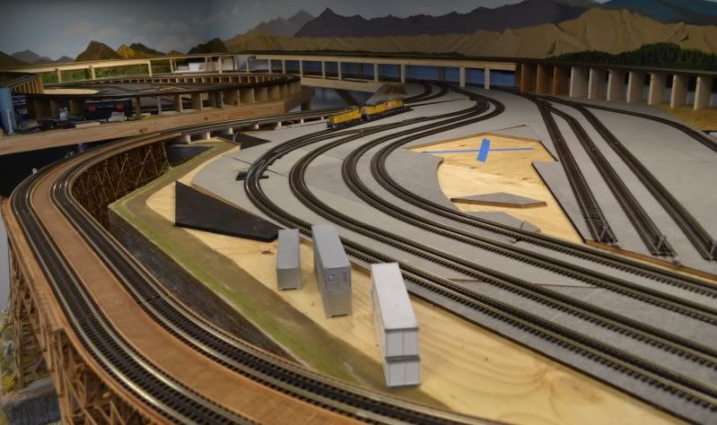
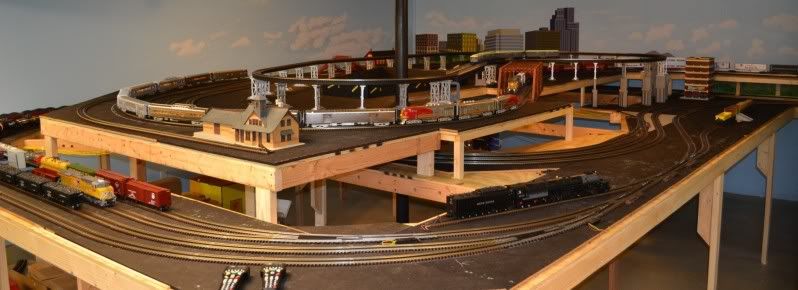
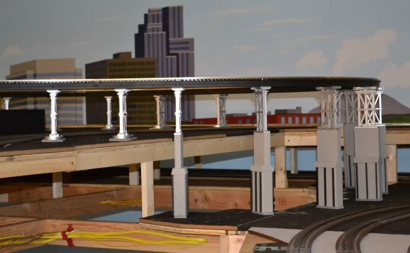
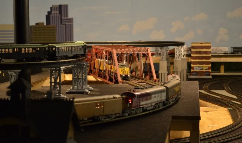
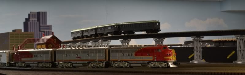
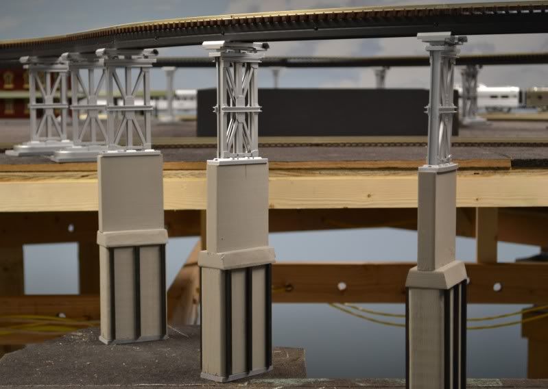
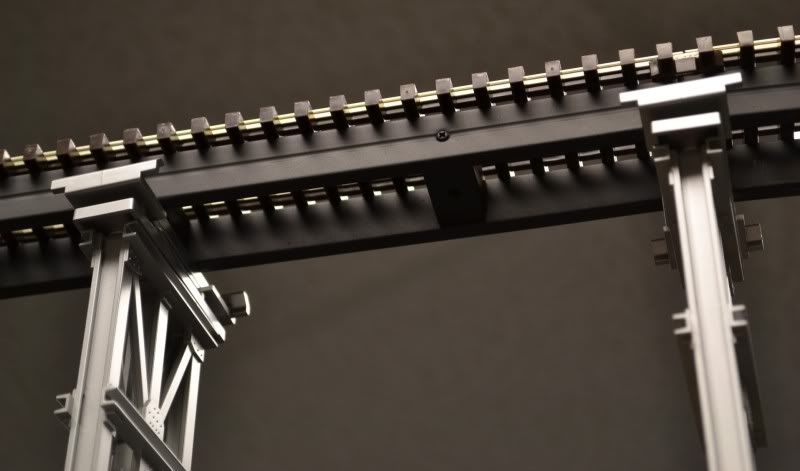
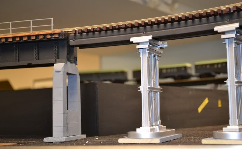
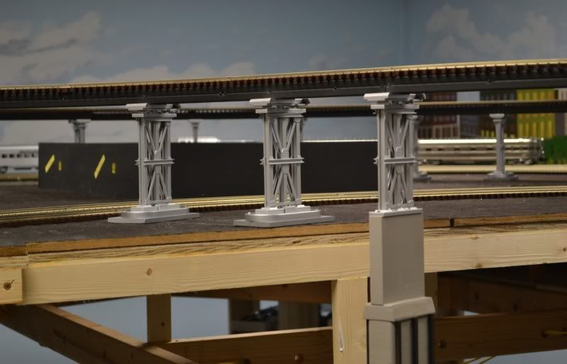
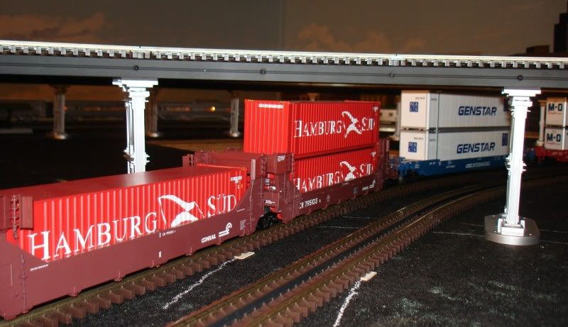
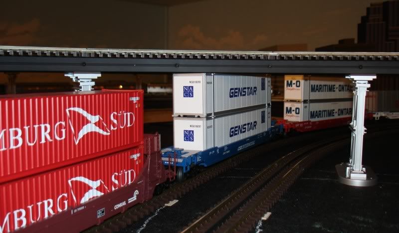
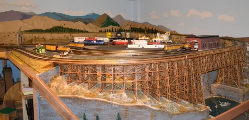
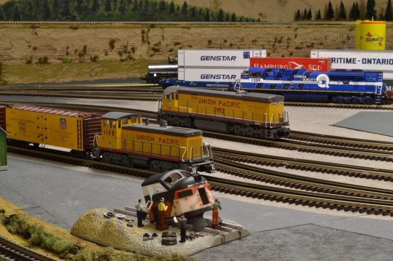
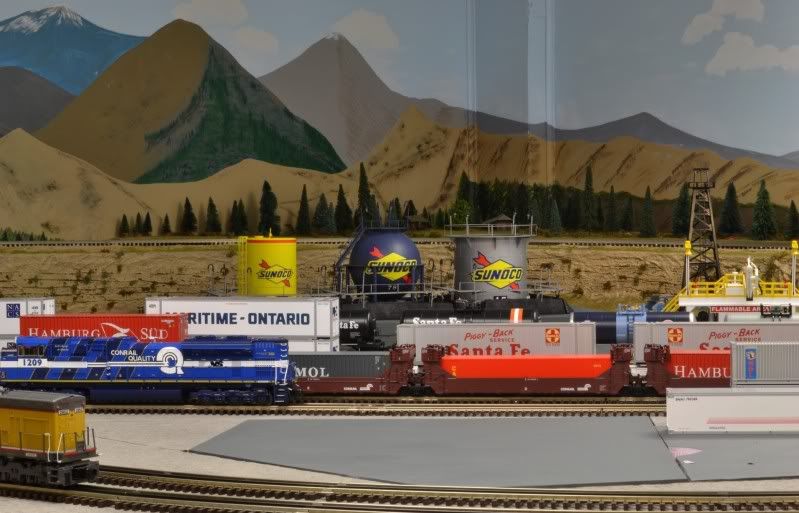
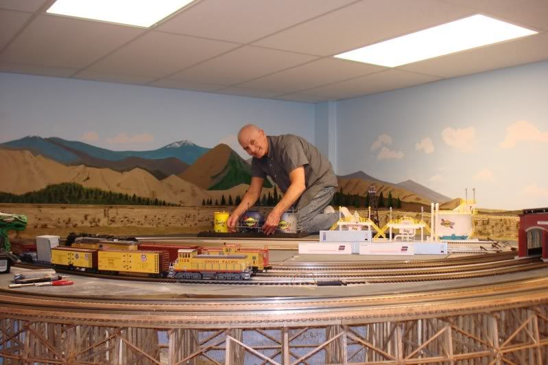
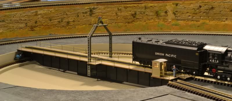
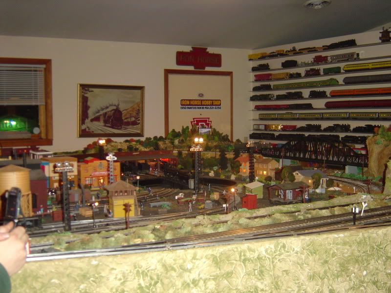
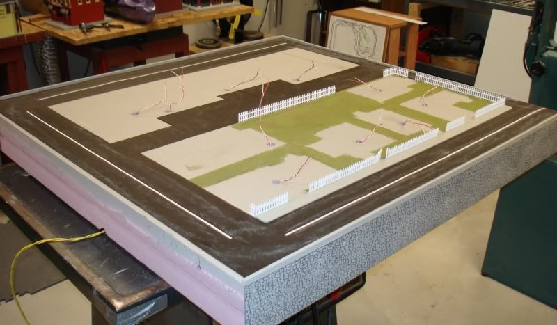
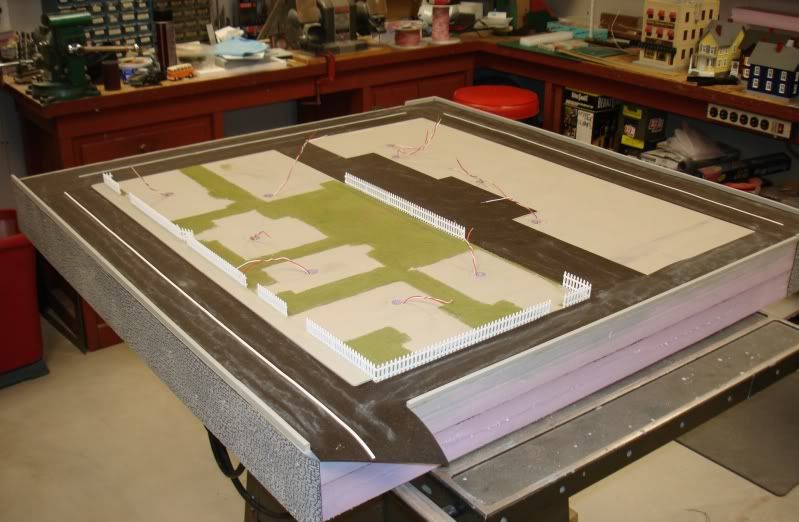
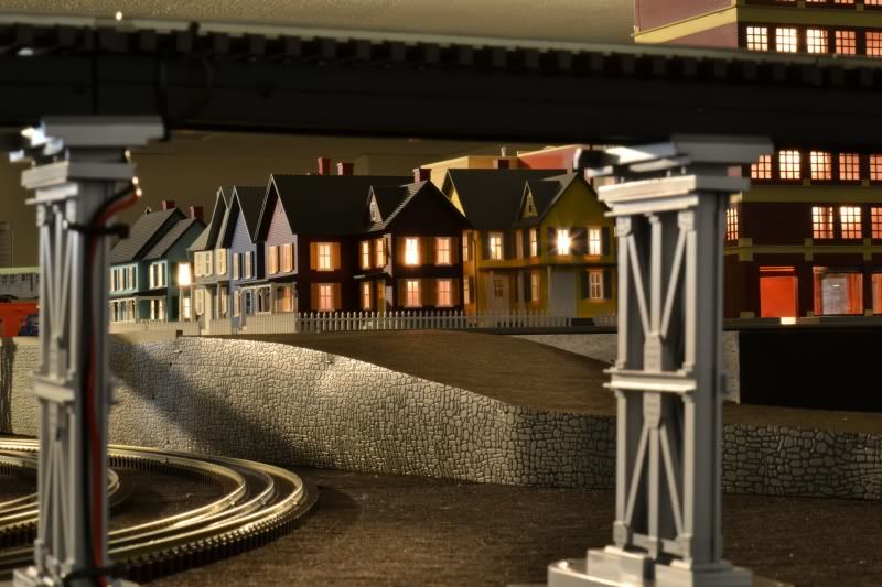
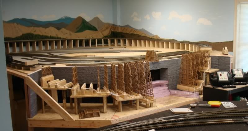
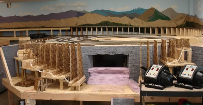
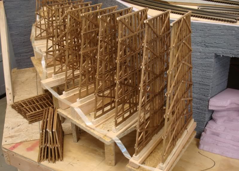
Here are some pictures:
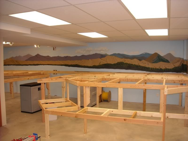
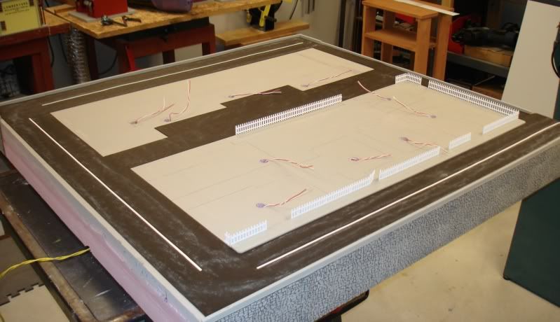
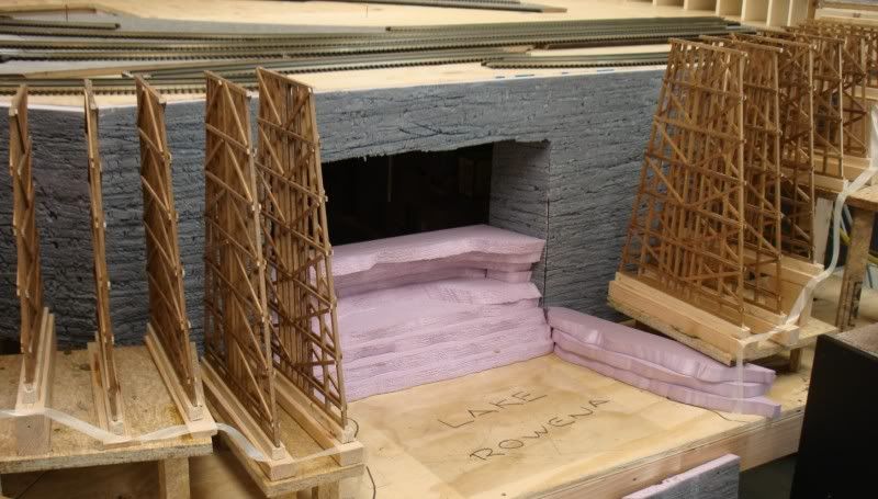
(Some of the bents in place but not glued yet as I have to finish the 'rock walls' first.)


Thank you for looking!

Alex

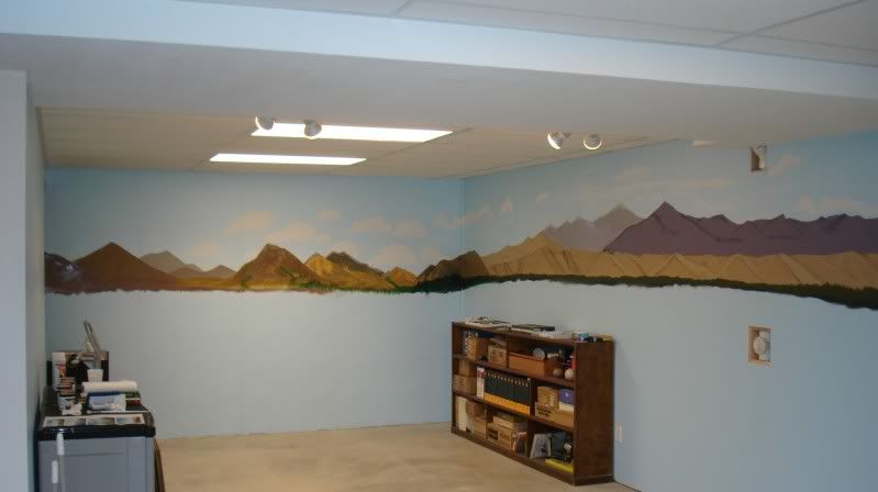
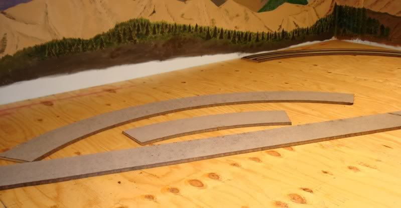
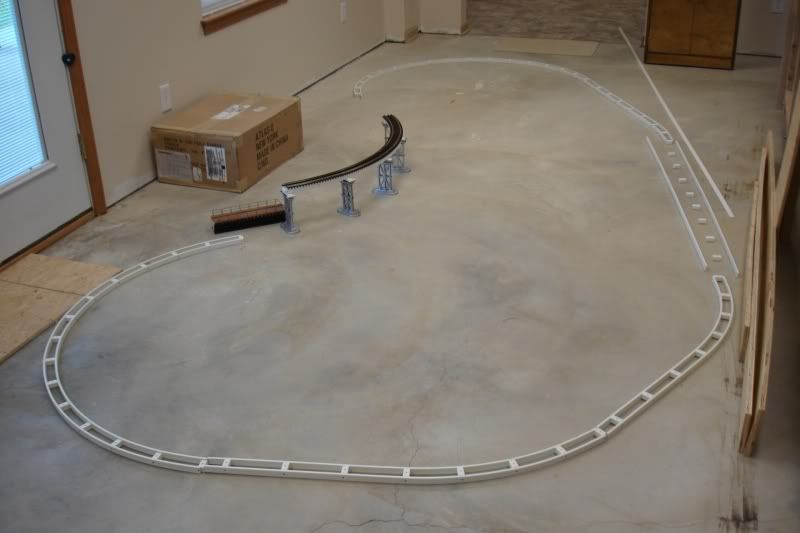
PS. The pink foam was an after thought (thanks, Patrick) and I ran out. Had only bought one 4x8' sheet to try it, liked it, and will continue using it. Will buy more tomorrow.
quote:
Originally posted by Tom Tee:
Humm..........enough wire to fill a gutter Eek..........Maybe go look again at Ed R's "They said it could not be done" thread on the 2 rail side.


...I like Rich's idea a lot better, but the gutter is hidden by the velcro skirt, and the wire is very accessible. The described layout was two-rail with a very sophisticated electrical command and control system started before the invention of DCC in HO. The control room had an electronic wall displaying the position of every train and every turnout on a 2400 sq. ft. layout. Lots of wire, and many members with very sophisticated computer and electronic backgrounds. The gutter was great, because you could modify a 70' wire by just reaching into the gutter, and locating and servicing that individual wire.

Alex, your layout is exceptional. Thanks for the photos! Cool

Cordially,

Dennis
Don, Dennis, Rich -

Thanks! Fun to post some of the work.

Had I found the type of trestle bents I wanted, I would have bought them instead of building them from scratch. Is not that they are not fun to build; they are. But they do take a lot of time.

The calculation of the bent heights, and the height of the piers and bases, combined with the 2% grade, and their location on a curve, was somewhat challenging. But once I had the XL spreadsheet done, it was a matter of cutting sticks and spacers to match the calculated heights; and measuring the spacing between the inner and outer bent cap ends for proper location.

Alex
Alex,

Looks awesome!

I really like your benchwork leg design.

It looks like the main leg determines the height.

I have two questions:

1. Did you do anything special to level the benchwork?

2. After doing the construction do you think that 2x4 is necessary for all the benchwork, or would 1x4 be sufficient for all or part of the framing?

Looking forward to more pictures Big Grin
quote:
Originally posted by StreamLiner01:
Alex,

Looks awesome!

I really like your benchwork leg design.

It looks like the main leg determines the height.

I have two questions:

1. Did you do anything special to level the benchwork?

2. After doing the construction do you think that 2x4 is necessary for all the benchwork, or would 1x4 be sufficient for all or part of the framing?

Looking forward to more pictures Big Grin

Tom,

Thanks.

1. I leveled it as I built it using a 4-ft and a 3-ft level. I cut all the legs the same length, and then used shims as needed.

2. I had always used 1x4'x for the frame of my previous layouts, and they worked fine. I made the legs out of the 1x4's as well, in 'L' shape. I went with the 2x4's this time because the 1x4’s were (are) getting harder to find straight and are more expensive. I used over 100 2x4’s for the layout, which my wife and I hand-picked at Home Depot and had them delivered. (I don’t have a truck.) Going with 2x4’s saved over $100 and allowed me to use the frame pneumatic-nailer. I used a combination of 3-1/2” screws and nails, depending on the joint, and glued all of them as well.

Now that I have the 2x4 frame, I am really glad I went with it. Not only is it very sturdy (I climb on top of it to lay the track and it is A-OK solid and stable), but it does not require as many legs as the 1x4 frame. Also, when it comes to joining two sheets of plywood, I always make the joint or seam fall on a frame member. This is much easier to do when you have a 1-1/2” edge instead of just 3/4".

I will post more pictures soon, and do keep us posted on your progress as well.

Alex
You mentioned how the DZ 1000 switch machines do not always throw the points all the way. I am new to these and mine do the same thing. I have never read of anyone else mentioning this problem on any of the O gauge forums. Currently I have only one loop operationable and it has one switch with the points against the stock rail so I dont worry about it. But soon another loop will be going and it has several switches. I need to buy one more DZ 1000. Should I buy it or something else. Do other peoples DZ 1000 throw the points all the way consistantly? Also you really have to locate Caboose Industries ground throws accurately or they wont throw the points all the way on one side if your off a little.
Dennis San Fernando Valley CA.
quote:
Originally posted by Dennis Rempel:
You mentioned how the DZ 1000 switch machines do not always throw the points all the way. I am new to these and mine do the same thing. I have never read of anyone else mentioning this problem on any of the O gauge forums. . . Dennis San Fernando Valley CA.
Dennis,
Yes, I still have the problem with the Ross switches. I posted this issue a couple of times and the suggestion has been to add a little oil to the DZ machine. I added the oil as indicated, but the problem persists.

NOT ONE OF MY RCS+DZ is working correctly - if by correctly we mean that the DZ machine throws fully each time. Again, the switches by themselves are free - no binding - AND the DZ machines exhibit the same problem by themselves. I have nine of the switches installed so far, have two of them wired so they will automatically throw (non-derail) and they simply do not throw fully most of the time. Sometimes the points throw fully even if the DZ machine does not, but they are not locked in place.

I don't want to start an RCS & DZ rant, but I always read how much better they are than the Atlas, for example. Yet, I have installed over 30 of the Atlas switches, and have not had any problems with any of them. Roll Eyes Go figure!

Maybe someone will chime in?

Thanks for posting Wink

Alex
quote:
Originally posted by DMASSO:
Alex. Have you increase the voltage a bit? . . . Have you tried a bench test to experiment with the voltage?
Hey, Don -
Yes. I bench-test every turnout before I add it to the layout. I use my KW's 14-v and 20-v for the test. Neither the 14-v nor the 20-v makes the DZ advance fully every time. With the 20-v, it looks as though occasionally they bounce back almost to mid point. I don't think that this is an optical illusion, but I have not taken the time to video tape it and then playing it back in slow motion. The Atlas turnouts work fine with 14 volts.

This has raised another issue that I had not faced before (with the HO Atlas turnouts - anyway): How do I know that the turnouts have actuated properly? With the Lionel Fastrack on my last layout, which was only about 7-ft x 20-ft, I could see the lanterns and knew whether they worked properly. (BTW, the Fastrack turnouts ALWAYS worked fine!)

What I am going to do is to place cameras over the areas that I cannot see from the control center. Some of these will be inside tunnels, and others just mounted on the wall and trained on the turnouts. This will be something else to work on AFTER I finish the track and wiring (so I can run trains other than point-to-point).

Thx!

Alex
quote:
Originally posted by Ingeniero No1
............................................................................

NOT ONE OF MY RCS+DZ is working correctly - if by correctly we mean that the DZ machine throws fully each time. Again, the switches by themselves are free - no binding - AND the DZ machines exhibit the same problem by themselves. I have nine of the switches installed so far, have two of them wired so they will automatically throw (non-derail) and they simply do not throw fully most of the time. Sometimes the points throw fully even if the DZ machine does not, but they are not locked in place.
................................................................................

Maybe someone will chime in?

Thanks for posting Wink

Alex


Alex: I have both switch machines. My Atlas switches go back almost ten years. I've done an extensive upgrade with the Atlas 6924 relay boards and 6931 dwarf lights. This added the electric non-derail and power routing I needed to smooth out a lot of electrical holes in a small layout with a lot of switches installed back to back. The 6924 relay boards have also eliminated motor burn out which was common with the Atlas switch motors.

The DZ 1000 are a completely different beast, with a small motor and gear drive assembly. Atlas snap switch are what I term a linear motor with two coils that shuttle the throw mechanics. The DZ switch has a NO/NC Three pole switch that cuts the motor circuit once the throw bar reaches it's limit. There is no adjustment on this limit switch which may be part of the problem. I have quite a few of these switch motors installed on the modular club T module. They can be problematic as you have described. I oiled, tightened, and loosened the screws several times and am operating at a 18 volts AC. Still there are some glitches.

Note the green limit switch in the two throw positions. Most likely it is cutting out before the throw is complete. At least that is the way my switches seem to work. I very seldom ever see the manual throw bar on top of the switch all the way left/right.


My thought is send them back until you get one's that work properly.
Mike

Alex Thanks You have really put a lot of effort into showing this forum what it takes to put a top notched layout together. That's time you could have easily used to advance your project.
Much appreciated and Thanks Again
Mike.
Mike,
I just read your post, above. I did not suspect that the DZ1000's were like that at all! I thought that they were of the dual-coil/solenoid variety.

Now that I see your excellent, fine detail pictures, I will look a little further, and post what I find, which I expect to be the same as what you just said. Wink

You also said, " I very seldom ever see the manual throw bar on top of the switch all the way left/right."

And do they work OK that way for you?


THANK YOU!!!!


Alex
quote:
Originally posted by Ingeniero No1:
Mike,
...............................................................................

You also said, " I very seldom ever see the manual throw bar on top of the switch all the way left/right."

And do they work OK that way for you?


THANK YOU!!!!

They do work, on occassion they will hang-up. Most of these switches are paired cross-overs, with two throws at once. That may effect performance. There are two throw buttons per switch set, one on either side of the module, along with a Lionel SC-2 control. Switches pictures are Ross 204 three-ways

Finish paint


Alex
Mike,

I videotaped the DZ1000 (with bottom plate off)

With 14v: Sometimes it works OK, other times it just goes part way BUT the switch points advance fully. The gear and pinion still lock them in place somewhat, so I guess it should be OK.

With 18v: I had one that buzzed! It went back and forth several times before it settled.

Adjustment: You are correct; there really isn't adjustment to be made. BUT, the limit switch (LS) does have a little play, and I was able to stop the 'buzzing' or continuous actuation under 18v by rotating the LS fully in one direction and then tightening the screws.

Bounce: It definitely bounces halfway back in one direction. It advances fully, then bounces back half way. You can see this plainly when playing it back one frame at a time (0.033 seconds/frame).

The three turnouts I tried seemed to work better at 14v, but now I have to go back to the other eight and try them out.


Steve C:
Glad you liked the trestle, and let us know how you do with yours. It actually is easier than it looks; just some patience and be careful where you stick your fingers and brush with your elbows when close to complete Wink


Alex
Alex,
Today was the first that I saw your postings. I am awestruck, Your benchwork, backdrop painting and popups are among the best ever offered here. I am amazed at the attention to detail on your trestle; just reading the process that you went through to ensure accuracy was inspiring. Having the space to build, the skills to accomplish what you are doing, AND the support of your Wife; you are truly blessed.

I can't wait wait for the next posting.

Oh, and thanks to you and Dom for the track gauge and wiring technique!
quote:
Alex, fantastic benchwork by a master craftsman. This benchwork would be a great article in the OGR magazine.

I can easily spot half a dozen very neat how-to articles for the magazine in this one thread alone, any time Alex is in the mood (or has the time) to do them. I'm easy to get hold of, and definitely will be following the progress of what is shaping up to be one dynamite layout.
Allan,
I will be emailing you shortly to review this further Wink.

Rob,
Thank you, but a EE will have to do Smile. Actually, I enjoy doing this type of work, and never look at what I have yet to do, but at what I have already done.

UPDATE
Since finishing the big trestle a few weeks ago, I have been building grades, building the upper level frame, laying and wiring track. All of the upper level track is in place, though not yet ‘screwed’ down. A lot of it is wired and tested, and only five blocks remain to be wired. So far everything runs great (I use DCS).

After the upper level is complete, as far as track and wiring goes, I will start on the “L” train. It will be a loop about 35 feet long and six to seven inches above the upper level. The single track girder bridge shown below, on top of short pieces of 2x4’s and next to the double-track Pratt Truss bridge, will be part of the “L” train. I made this bridge from scratch for my previous layout, and will have to shorten it by about 14 inches, but it will work fine.

Here are a few pictures I took just a few moments ago to share with you. Not great, and I will have better, more detailed pictures soon, but these will be OK for the time being to show some progress. I took all the pictures, except for the last two, while standing on a 17-inch high platform. I will have several such platforms for people to watch the trains. Hope you enjoy them!

East side frame underway.


West Side - grades.


Tracks connecting the East and West sides.


East Side (main side: has lower, upper and "L" levels)


This next picture taken while standing on the floor.


This is another picture taken from ‘ground level’. It is of the track sections that connect the East and West sides, and it is behind the stairwell. This is where I want to install cameras to monitor the turnouts.


And thanks for looking Smile

Alex
Have some more pictures to share with you. Some would precede the last pictures I posted chronologically, but I did not post them because I thought they may not be of interest. But maybe they would be . . .

Laying out the second graded track


Some construction details of the East side, where the lower, upper and “L” levels will be. (The West side has lower level and graded tracks.)


Clearances with the MTH Premier Big Boy on Ø99 inner curve. The SF passenger train is on the outer Ø108 curve. So far I have had no interference problems, even when running the Big Boy and the Coal Turbine No. 80 side-by-side, whether either is on the inner or outer curves. The Ø108 and Ø99 are spaced 4-1/2" apart throughout, as are the Ø99 and Ø90 used in a few places.


Newly completed and painted Pratt Truss Bridge. The ‘higher’ bridge is for the “L” train.


And one overall of the East side.


Thank you for looking!

Alex
Alex,
All I can say is 'AWLSOME'. I hope I can do one tenth as good with my next layout, if my house wasn't for sale I'd start tearing down my layout now. I am new to this hobby and have my first layout since I was very young, made a lot of mistakes, hope I have enough years left to do better.

How often do you connect to the track, what is the spacing between connections? Your wireing diagrahm shows spread out connections.

I hope when your layout is at least near completion you will accept visitors.

Keep up the 'GREAT' work and thanks for sharing.

Mike Orite
Mike,

Coincidentally, I just happened to briefly describe my track connection in a thread in the DCS forum. Here is what I said:
Presently, I have the entire track in place and wired; that is, except for the “L” train, which will be a separate, isolated 30-ft loop. (See below). The turnouts are not wired yet for control, and neither are the relays and switches to turn the track districts and blocks on and off.

Each of the dual mainline tracks (275 feet per) is divided into 10 districts, and are fed by one of the eight channels (two TIU’s) so no two adjacent districts are fed by the same channel. The 24 sidings and spurs are also distributed among the eight channels, such that each channel terminal block has no more than six tracks connected to it.

The wires from the terminal blocks to the tracks range from eight to 16 feet long, 16 AWG. The eight wires from the TIU output channels to the terminal blocks are 12 to 20 feet long, 14 AWG. And the four wires from the two Z4000’s to the TIU’s are 40 and 100 feet long, 12 AWG. I still have the magic light bulbs at each TIU output channel, and now have Deats Filters at the end of each spur. I am in the process of adding more filters.”


There have been comments made, all of which are fine, and some of our friends do not believe that it is necessary to have so many track blocks and feeds. They may well be right, but it will not hurt to do it as I have done it. Also, this approach is recommended by Rick Melvin in the DCS video, as well as by Barry Broskowitz in his DCS book, on page 60.

I have made a few modifications to the layout, and this is the track plan now. I will probably add a turntable (CSX AL will be hearing from me soon) and roundhouse at Villa de Rocas.

UPPER & "L" TRAIN LEVELS


I am making the support for the ”L” Train out of plastic molding from Home Depot, and will use Railking Elevated Trestle Sets. The long empty span on the left of the picture is for a bridge over Lake Chiemsee, which already is up on the layout.


And thank you for your comments!

Alex
Last edited by Ingeniero No1
All the track is done (except for a couple of minor changes where the turntable will be) and I am ready for scenery and switch-track and accessory wiring. Once the scenery is in place, a lot of the lower level track will not be seen from the main viewing area. It will always be seen from the back of the layout.

Anyway, I decided to take some pictures of the overall as it now stands to share with you.

This is one of the viewing platforms. It is 16” high, 60” wide and 24” deep. There is a step up to it. Other platforms, in the aisles, will be a little lower.


Finally unpacked a few more of the locomotives.


The rest of the pictures I took while standing on the floor or from a viewing platform.


The "L" train track 'loop' is 32-ft long.


The longest straight stretch, along the back - about 36-ft.


This is where I will have the turntable and 3-stall roundhouse, so the layout will change somewhat.


I hope that wasn’t too boring.

Thanks for looking!

Alex
Thanks, Don!

George,
The support beams for the “L” train track is made of 1/4” x 3/4" simulated-wood plastic molding, as shown in my post of 05 August, above.

The silver piers are Railking, and the taller supports are made of 1x4’s on top of 2x4’s with an intermediate 1x4 piece. I then added some 1/4" square pieces on the sides of the 2x4’s. There is no prototype for this – I just made something easy to make and hope that it looks somewhat real.


When I first made the “L” train structure, I measured the double-stack cars and containers I had, and I had enough clearance. But then I bought other cars and containers, and oops! I had a problem. This required the additional 1/4" piece at the bottom of every pier and support. This results in a clearance of about 6” above the rails of the track under the “L” train.


Interference before the additional 1/4" base.


Hope this helps.

Alex
DPC,
As luck would have it, most of what I painted (the buildings) will not be readily seen; the real structures that I plan to have on the second level will block the view from the main viewing area. From the side aisles you would be able to see more of the backdrop, but the attention would be towards the layout. This having been said, I may still try the dull coat since I am not done painting yet. Wink

Cesar, Mike – Thank you!

I think the whole layout will take on a new perspective with the scenery, and I can hardly wait.

But then will come the buildings, and working accessories, and more wiring, and trees, and cars, and people - - - and computer control . . .

What a wonderful hobby we have! Smile

Alex
Thanks, Peter!

Now I am trying to decide how to change the layout to accommodate a Millhouse River Studio 34” turntable (TT henceforth) that should arrive soon. Originally, this area of the layout, Villa de Rocas, was for the Lionel Rotary coal unloader, which after almost two years of delays they have decided not to make available.

The layout on the left shows the existing Ø72” elongated loop where the coal train would have gone through the rotary dumper, and the switch-tracks very close to how they are; just slightly modified.

The layout on the right is removing the existing Ø72” elongated loop, all exiting switch-tracks, and starting with a clean slate.

The roundhouses (RH henceforth) shown are not accurate as I do not have any yet. The spacing between the tracks out of the TT is about 8° in both layouts.

On the left, the RH is 30” deep, 24” across the front, corner-to-corner; and 50” across the back, also C-C. The distance (tracks) from the TT to the RH is about 8”.

On the right, the RH is 32” deep, 28” across the front and 54” across the back. The distance from the TT to the RH is about 16”.

I do not have to have a six-stall RH, and a total of 10 tracks served by the TT would be enough. Removing the TT will provide the access hatch for maintenance.

(Oh, the blue and dark-green tracks on the perimeter are the main tracks, Ø108” and Ø99”, graded 2%.)


It would be easier for me to do the layout on the left, as it requires fewer changes, but I really I would appreciate your opinions Smile.

Thx!

Alex
Alex....the invitation is still good if you want to come on down to take a look at the layout. I have incorporated much of what you are trying to do on your layout and it may be helpful for you to see it in person. Our rooms are very similar in size so if I can be of any help, just let me know. Your progress is coming along nicely!!

Alan
Alex,

You'll be happier with a straight track leading to the TT like in the left hand drawing in your 9/5 post and in Patrick's suggested modification. Large locomotives and a curved lead-in track like in the right hand drawing in your 9/5 post can be problematic. Long wheelbase and articulated locomotives will try to push the bridge in a clockwise direction possibly causing it to move out of alignment.
Alan,
I have not forgotten! I’ll be in touch soon. Thx!

Bob,
I appreciate the advantage of a straight lead track to the TT. Here is what I have come up with, using Patrick’s overall sensible recommendations. Keeping the loop around the TT and RH really opens up a lot of possibilities, including a rotary coal tipple in the future. More immediately, however, I have a number of operating accessories that I can certainly fit around the track paralleling the longer straight portion of the loop. (The accessories shown are not the actual ones I will use there.)


Also, even though I have double reversing loops for each main, this small loop around the TT and RH (even after I increased its smaller curves from Ø72" to Ø81") is a lot faster to use to turn around a shorter train, say 15 cars or so.

Thanks!

Alex
Alex...I am at home right now for a lunch break and just saw this. You have done a really great job fitting the turntable into the space you have created!
I see that you may not be able to have a roundhouse like you wanted but the engine houses lined up are certainly protypical and as you saw on my layout I used this approach for additional service area for the locomotives. Keep up the great work!!

Alan
Alan,

You are right - instead of 'shoe-horning' a roundhouse, the double train shed, and perhaps another single, work fine. I will add an extension to one side of the double shed for the Big Boy.

Here is where I am. The covered rectangular hole adjacent to the TT still is a hatch, about 13" x 25", and I may add a couple of 'whisker' tracks (correct name for tracks around the TT?) or perhaps just a building or small tower on top of this hatch - it lifts straight up in this case.

I like having the big TT hole for major work, but the smaller hatch will come in handy for minor adjustments.


(I'm also working on a small modification to the roof of the shed; Judy did not like it flat!)

Thanks for you comments!

Alex
Chris,
Thank you for your comment; much appreciated.

Steve,
The room is 33-ft x 38-ft and I use most of it. Here is an updated track plan of what it is now after a couple of spur additions and final configuration of the area around the turntable.


. . . and yes, I am having fun with the scenery. In addition to the pink foam, I am using the more traditional paper towel (blue) dipped in plaster, but instead of plaster I am using Structolite, and what a difference! Wink About three years ago I learned about it from Jim Policastro, but had a limited opportunity to use it on my then (small) layout. Not this time! Big Grin

Thanks!!!

Alex
I have done some more wiring and have started the scenery in the Etieca Valley and Villa de Rocas areas.
Here are a couple of shots of each.

Etieca Valley will have a small refinery, Intermodal Facility, and Diesel Service Shop.


Far, far away beyond the refinery and the double track main there are a couple of hunter cabins. HO scale and smaller trees worked just right for the desired effect.


Villa de Rocas is home to the turntable, engine shed, and some industry.


Of course, all of this is far from finished. . .

Thank you for looking.

Alex
quote:
Originally posted by willbacker45:
Just saw your video of the Big Boy! Very cool! I didnt know that you were the one that had the amazing fastrak layout I was always blown away by that one and was sad when you took it down but your new layout is obviously going to be spectacular!
Yes, it was sad to take that one down because it actually turned out fine. But better things were in the horizon, and I am working on them now. THANK YOU for your comments!

I wasn't sure about this video, but since you thought it was OK, I'll post it.
• It's a new camera - for pictures (Nikon D3100 DSLR) and I don't really know how to to properly use it yet;
• The turntable is not finished (But I'll get it done ASAP, so Al Z. won't get mad at me).
• It is a raw video. . . no editing or anything.
But I just had to try it.


Thanks!

Alex
quote:
Now its run nights and layout night!

Patrick -
It sure was a lot easier to work on the layout a few months ago - it was all building the frame, the top, and laying track. But now, I have to choose: Scenery or run trains, more wiring or run trains, setup buildings or run trains, control panel or run trains. Running trains wins too often Big Grin

Don,
Yes, Al's turntable is a joy to work with. I am assembling the bridge now and should have a few pictures soon. That whistle - - I was going to 'quill' it, but between running the video, the turntable, and the loco, I forgot!

THX!!!!!!!!!!!!!!

Alex
quote:
Is that a Lionel Big Boy or the MTH model?

Alan,
That is the MTH 20-3414-1 from 2010 Vol-2. I really it.

I was lucky to find one when I did as I did not realize that I had the 2010 Vol-2 issue (the spine of the book says Vol-1 !) and had not looked at it. That was shortly after we moved (Aug 2010) and I did not realize that I had the Vol-2 catalog until I unpacked.

I called Jimmy, who was winding down at the time, and he did not have any, but thought that Jason might have one. Sure enough - Jason had one and I bought it. That was around Sep-Oct last year.

I'll have another video soon . . .

Alex
Al,

The wire 'was' tucked in at one time. I'll try to secure it better next time. Wink

Colors (not following any prototypes - just what I thought would look OK. Eventually I'll add some weathering, but for now it will have the fresh look.

Rust-Oleum Camouflage 1919 Deep Forest Green = The arch, stanchions, and motor gears
Rust-Oleum Camouflage 1917 Khaki = Shanty
Rust-Oleum Ultra Cover 249082 Satin Colonial Red = Window frames
Rust-Oleum Metallic Finish 7715 Aluminum = Ladders
Railroad Colors 110145 Boston Maine Blue = Motor and bearing blocks
Testor’s Yellow = Handrail (I used a brush, but it would have been better sprayed – I just forgot and assembled it before painting.)
Testors' Red = Ball on top of rotor (which is free to rotate so I can add the wires to the power pole.)

Thanks for the nice comments!

Alex
A logo for my railroad.

The tracks that join the east and west side of my layout are located behind the stairwell, as shown below. Although these tracks and switch tracks are easily accessible from the service aisle, this ‘pass junction’ is hidden from the main viewing area and from the control center, hence the name of the railroad.


What do you think?

I have been working primarily on the controls and wiring over the past few weeks, but in a couple of days I will post pictures of the other progress I have made.

Thank you for looking!

Alex
Thanks, Marty!

Believe it or not, it is now harder to work on the layout than it was earlier. No, it is not that the tasks are more difficult or anything like that; it's just that now I have some many more things to are ready to be worked on that before!

In the beginning, it was easy: make the bench frame, then the plywood and Quiet Brace top, and the graded track supports. That was followed by the track and basic wiring.

But now, EVERYTHING is ready and waiting: Scenery, turnout wiring and signaling, block wiring, control panel, buildings and structures and weathering, ballast, streets, and the list goes on. Sometimes I start working on one of these only to leave it to work on another.

Oh well, at least I am assured of not running out of things to do! Big Grin


Thanks for looking!

Alex
Patrick -

"Hide the remotes"

Good idea, but unless my wife hides them, it wouldn't work (and I won't let her have them Big Grin)

"Schedule?"

I try to work on at least two different areas everyday, but that's about it. I am trying to work on the layout close to the same number of hours as I did on my regular work before retiring.

"Did the engine(*) show up today?"

Yes! And it works fine! It is great! I'll post some pictures and maybe a video - soon.

Thx!!

Alex

(*) The engine is a Vision Challenger that was a Christmas present and it did not work right out of the box. I shipped it to Lionel on their UPS calltag exactly two weeks ago, and received it back today.
Alex,
Just incredible sir, you have the space and talent to engineer and build what so many of us would love to own. I like your choice of track and switches also, your realistic look is great stuff. I have always built to accomplish the Tin Plate toy train look, however after seeing your layout, I now really like the realistic look also. Great job sir!
PCRR

Some of the men in the old Iron Horse Train club at the realistic office layout,
who would appreciate your fantastic work. From a time gone by.


Last edited by Pine Creek Railroad
PCRR –

Thank you for your nice comments! Those are really nice pictures you posted of a fine layout.

I started reading this forum about the time that I started in O-Gauge after many years of HO, and my HO layouts were pretty good, but I learned the challenge of realistic detailing and how to accomplish it to the forum. Sometimes my engineering mind gets in the way, and I end up spending too much time in the planning or in getting something done a certain way when it really is not necessary.

However, I admit that I enjoy all of it! Realism is something I try to model, but since I like the operating accessories and cars, there will be some areas on my layout that may not be quite prototypical in every detail. But then again, operating accessories was one of the reasons I left HO and came to O-Gauge – it is just plain fun!

Thanks!

Alex
quote:
Originally posted by Ingeniero No1:


Far, far away beyond the refinery and the double track main there are a couple of hunter cabins. HO scale and smaller trees worked just right for the desired effect.

Alex


Wow - incredible. You have talent. I have been following this since you began. It's hard out here to have a house with that much contiguous space to create an empire like you have (no basements). Thanks for documenting your journey - it's fun to watch.

Ted
Ted, Dennis -
Thank you for your nice comments - I really appreciate it!

I have been working on buildings and other structures for the layout, and finally finished the raised city block at Madera Heights. I still have to add people, vehicles, and light posts, but the main part is done. Also, the inclined drive down to the main level still needs a little work.

The raised portion base consists of two 2” sheets of pink insulation to make up the 41” x 42” area. Not very big, but it fits nicely where I need it.

The raised area is represented in my layout, below, by the blue rectangle on the upper view, and dotted rectangle in the lower view.


I laid out the buildings, cut holes for the wires (used a 5/8” diameter brass tube to which I added a serrated edge), and carved the groove for the wires so all can be connected at one point.

The streets are roofing paper with grey chalk, and they look better than the pictures show. The grass and other details cannot be seen easily, but when I have a train car mounted camera, those details will show up.


Here are three shots. I posted more images in the 3-Rail O-Gauge Trains forum section here: Madera Heights Uptown.


Thanks for looking!

Alex

Thanks, Patrick!


Now the real fun begins - wiring.


There will be 232 wires going to the panel itself:

• 46 for the toggle switches that turn the track-block relays on/off

• 92 for the toggle switches (center off, spring return on-on) that control the turnouts

• 92 for the bi-color LED's that indicate the turnout points direction

• 2 commons - 12VDC for the LED's and relays, and 18VAC for the turnouts


It will take a while, but the layout is operational using the DCS remote for the turnouts, which will remain so even after the toggle switches are wired, and the track-blocks will remain always on until each of the 6-relay modules are installed.


Thanks for looking.


Alex

Leandro, Don –

Thanks! Glad to share.


Rich,

That is a good question. The LED’s are 12VDC at 20ma, the panel switches for the relays operate 12VDC at about 80ma, and the ones for the turnouts 18VAC at a bit higher current but for just an instant. This allows me to use 22AWG wires (stranded for easy flex) from the panel to the terminal strips in the control cabinet.


From the control cabinet to the layout I do plan to use some sort of multi-position connector, as you mentioned, but will use 18AWG since some of the runs can be quite long. I’ll post with my wiring progress and what I end up using.


Thanks!!


Alex

Alex,


Yes, you are right. The (my) problem now is how to divide my time among all that needs to be done 'next', and defining what is 'next'.


There is the wiring, and finishing development of the turnout-points sensors, and structure weathering, and general scenery, and ballast, and vehicles, and little people, and fascia, and . . . the list goes on.


It was easier early on when I had the background to paint, then the benchwork, and then the track. After those were pretty well done, everything else came up (or became available) all at once!


I guess just take it one day at a time, rotate chores so as to not get burned out (fat chance), and remember to run the trains once in a while for relaxation.


Thx!


Alex

Yes Alex thats what I did not to get bored or burnt out

keep switching from time to time and before you know it

a lot gets done.


ALEX I SAW THAT YOU PURCHASED THAT UP FEF 8444 IN GREY

I WAS THINKING ABOUT IT.THATS A GREAT PURCHASE.MY FRIEND

MIKE R HAS ONE AND HE RAN IT ON MY LAYOUT,ITS AWESOME

I,M GLAD YOU GOT IT.LET ME KNOW HOW YOU LIKE IT.


THANKS,ALEX

Alex,

I'll let you know how that 4-8-4 works out. It will look good next to my grey Challenger .


Here are a couple of pictures of a semi-logging facility I added at the southwest empty corner of the layout. I will load log cars there, pull the cars with the Shay, and unload them at another spur.


03 Logging med crp DSC04726


04 Logging med crp DSC04736


Thank you for looking!


Alex

Attachments

Images (2)
  • 03 Logging med crp DSC04726
  • 04 Logging med crp DSC04736

Wippen,


No problem. Here is the latest image of the layout (pretty much up to date), and the RR-Track file.


One difference is the observation platform construction in the aisles - they are or will be 10" high, and there are no steps; instead, I built ramps up and down from the platforms, and these seem to work fine.


Overall Layout - Combined View 04 RD


Let me know if you can open the RR file.


Enjoy!


Alex

Attachments

I have been tryin to post a YouTube video following the instructions provided:


1.access the video on YouTube

2. Select Share

3. Select Embed

4. Copy the code displayed

5. Paste it here


But this is all I have been getting:


<iframe width="420" height="315" src="http://www.youtube.com/embed/GnDBTD3iN-8" frameborder="0" allowfullscreen></iframe>


If you click on the underlined link, it works, but how should it be done so the opening frame of the video is displayed?


Thx!


Alex


Alex-

Thank you so much for the RRTrack file. That request was actually from my eleven year old son. He is very into trains and designing layouts. He is in the process of learning RRTrack software and fell in love with your layout. I am sure he will have many hours of enjoyment with your layout file.


We are planning our own layout in space that is very similar to yours, though a few feet shorter. We could never build something as complicated, but will certainly, I am sure get many wonderful ideas from your layout.


P.S. - I am so impressed with it too! He better give me some time on the puter!

Wippen,


Attached is another RR-Track version of the same layout. The only difference is that I separated the upper level and "L" tracks from the lower level and graded tracks. It is just a bit easier to see and to work on.


If you look carefully, you will see that each of the double mains has a double reversing loop. There is another reversing loop around the turntable, but that one is easy to spot.


So glad to see your son involved - that makes my day  !


Thanks!


Alex

Attachments

Alex, your layout is spectacular... and what you have documented thus far is an inspiration to us all.  This is the first night I've actually read through your entire thread.  Thank you so much for sharing!!!


I have taken the liberty of pasting your youtube link into my post here so that the video displays directly within the forum.  When I created this post, I clicked on the vertical filmstrip icon that is two icons in from the right side of the editor toolbar.  And that opens up a dialog where you can either upload the video directly to the forum's server (based on the video file format) or simply point to an already uploaded file that exists somewhere else, which in this case was your Youtube video.


Enjoy everyone!!!


Thanks again for sharing your terrific talents with us, Alex!!! 


Best regards,

David

Last edited by Rocky Mountaineer

David,


Thank you for your nice comments and for posting the video link. I had not tried clicking on the filmstrip icon; I'll try that next.


I think a good portion of the enjoyment of this hobby is sharing what we know and what we do, and in the process we learn a lot as well. Unquestionably, the OGR forum is an excellent resource for this!


Thx again!

Alex

Originally Posted by Ingeniero No1: I wish that I had your artistic ability. Post a track plan if possible.
 
Lou
 

Finally started on the layout! But first, following your recommendations, I painted portions of the backdrop. I guess I am more of a carpenter than a painter, but it this will do for now. A couple of shots before starting the fun part.


A new leg design so the frame rests on the legs instead of on the screws that fasten the leg to the frame. (BTW - I just noticed that the camera distorts some of the images - the legs ARE SQUARE to the frame when done!)


Saturday:
Assembling one of the cross braces –


An afternoon’s worth of work - how it looked Saturday night (12' x 12' section):


A now to continue . . .

Alex


Hi Alex, Im Jake, you've been corresponding with my father. I have a love for trolleys that hit back and forth between bumpers. I use N scale along with O gauge. I do not know if i should expect you to know this or not but do you know if N scale trolleys also hit back and forth between bumpers also? Or do they just have the ability to go on a track without ending.

Wippen -

TRACK GAUGES

I can't find the original posting regarding the Track Gauges - it was back in April 2011, and is gone. Don may still have his material, however.


I made my gauges our of 3/4-inch, 13-ply birch plywood. They are 2 inches high and I used a thin kerf (3/32-inch) blade to cut the slots. I used a fine file afterwards to make the slots slightly wider as needed. The widest slots ended up at just a hair under 1/8-inch wide, and the gauges fit curves as well as straights. I used track spacing of 4-1/2 inches throughout the entire layout.


Track Gauges -3- med crp DSC03522


I could not have laid the track as I did without these gauges OR without scribing the curve radius on the surface. Using the gauges and the home-made large compasses, I was able to exactly match the RR-Track layout. I ended up cutting over 130 track sections, straights and curves, and I cut them exactly per the RR-Track design, and they all fit perfectly.


One thing I learned was that even when using sectional curved sections and joining them so there were no gaps, the resulting radius or diameter could be off by two inches or more from what it is supposed to be. Best to scribe the theoretical radius or diameter, and lay the track over that line.


Jake -

I do not believe that there are such trolleys in N-Scale. Many years ago, back ini my HO days, one of my sons was into N-Scale. He had trolleys too, but just the regular type. I did a quick Google search and did not find any.


F.Smaritano

Thanks! It was fun building the bridge and recording what I was did - just in case.


Thanks for looking!


Alex


Attachments

Images (1)
  • Track Gauges -3- med crp DSC03522

400e,


I have tried different size drill bits, and have settled on No. 48 (0.0760), but 5/64 (0.0781) works well also - for 16 AWG stranded wire and the No. 0 screw; that is.


After I drill the hole and insert the No. 16 AWG stranded wire (26 strands of No. 30AWG), I use a pick to separate the strands to make it easier to start the screw.


Let me know if I can be of further help.


Thanks for looking.


Alex

400e,


From Micro Fasteners. I tried different head configurations (button head socket, slotted, and phillips pan head) and these worked best for me:


Product No. SMPPK0004

Pan Head Sheet Metal Screw - Phillips

Size: #0 x 1/4

Finish: Black oxide

Price: 100 for$ 4.30


 http://www.microfasteners.com/...products/TWSSMPP.cfm 


While at their website, look at all the other stuff they have . 


And Thank You for your nice comment! 


Alex

Here is one of the areas I have been working on - around the turntable. Not done yet, but is getting there. All the tracks are fully operational (powered one at a time, with a rotary switch), and the indexing still is manually aligned (two speed) waiting for the automatic indexer (Dallee) - Thanks, Patrick.


 Birdseye view -

01 Turntable Area med crp DSC_0488


Challenger ready to go into the shed.

02 Turntable Area med crp DSC_0479


Railroad workers house -

03 Turntable Area med crp DSC_0496


MTH 4-6-4, Legacy 4-8-4, Legacy 4-6-6-4, MTH 4-8-8-4

05 Turntable Area med crp DSC_0512


Older gentleman sitting and admiring the engines - and a couple of fellows having a talk -

06 Turntable Area med crp DSC_0513


Thank you for looking!


Alex

Attachments

Images (5)
  • 01 Turntable Area med crp DSC_0488
  • 02 Turntable Area med crp DSC_0479
  • 03 Turntable Area med crp DSC_0496
  • 05 Turntable Area med crp DSC_0512
  • 06 Turntable Area med crp DSC_0513

Hi Alex, that look's beautiful as always.

Can't wait to see it finished.


Alex I just received my turntable from CSXAL this week.

I just started the install and wanted the thank you for all

the info you post here, because it helped me so much.

I used a lot of your method's for this install.I will post

all photo's when I'm done.THANKS AGAIN, ALEX


Alex did you get the challenger back yet.


THANKS ,ALEX

Alan, Roger -

Thank you - I have learned a lot and I am still learning from your fine work, and maybe it is beginning to show  .


Alex -


It is a nice turntable for sure - very well built, and runs so smoothly . . .


I have had it up and down (hatch opened and closed) many times in the past few days. It seems that just a minute after I raise it and button it up, I see or remember something else that I need to do that requires access 'through the TT hatch'. It is such a big hole that it is the nicest access I have in my layout. Don't hesitate to post or to email me if you have any specific questions.


Yes! I received the Challenger and it is runing fine again. I will now update that thread. (Completely forgot about it - thanks for reminding me.)


Thx!


Alex


 Here is a picture from two days ago.


Whisker Tracks HPJRR 02 med crp DSC04893

Attachments

Images (1)
  • Whisker Tracks HPJRR 02 med crp DSC04893
Last edited by Ingeniero No1
Originally Posted by Ingeniero No1:
Yes, the carts are working even better than we expected.

Glad to share what I am doing.

I finally made one of the several hatches I will need. This one is 14 x 18 inches, and although it is OK, the next one will be 14 x 20 inches. I used a Ø1” closet rod that I had, and it works well. Also, I will space the two supports further apart, perhaps 3 inches instead of just 1-1/2 for better stability. As they are they hold the hatch fine, but when raising it and lowering, it vibrates somewhat, and I hope further apart spacing will help.

The pictures should show what I did, but if you have any questions, p-lease let me know – I also have drawings.

The hatch lowered, in place.


The hatch raised and turned or swung.


Birds-eye view.


Underneath – hatch lowered.


Support detail.


Support with hatch raised.


Will have more pictures tomorrow.

Thx for looking.

Alex

Hope you don't mind but I am gong to have to steal your idea here and use it on my own layout.  Great job.

Glad to hear that the idea may be useful to you as well!


A couple of hints:


(1) Make the tube long enough to allow you to stand under the hatch without having to rotate it out of the way. I made one long and one short (because the tube I had wasn’t long enough to make them both long), and the longer one is nicer to use as I just raise it and stand under it. The shorter one requires that I raise it and then rotate it; no big deal but not as easy.


(2) Coat the tube with wax or something similar so the tube slides easily; it makes a big difference.


Good luck!


Alex

Originally Posted by Ingeniero No1:
Hey Patrick!

(Background painting is quite a learning process - thanks!)

The top of the frame is 47”, and when I add the 5/8” plywood and 1/2" QuietBrace, it will be just over 48”. I have tried different heights, starting at 36” and up to 44” which was my last layout – my first O-Gauge. (BTW, I am 5’11&rdquo

The reason is to make it easier to get under it. My back is not what it used to be, and I like to be able to sit on a short stool to do wiring without banging my head. (I have no hair left on top of my head to tell me that a 1x4 or 2x4 is in close proximity Smile) Also, the perspective for viewing the details is better in most cases. But since you cannot see the whole layout or get a birds-eye view, I will have a couple of platforms, about one foot high, from which to see the layout.

The main level will be 48”, the second level 57” and the “EL” train will be at 66”. My wife says that while standing on the floor, the “EL” train will appear to her as the real thing – she will have to look up to it. There is a lower level up front that will be 25” high, but that will be a gorge for my long trestle. I should finish this portion tonight or tomorrow night, depending on what time I get home from work, and I’ll post some pictures. BTW, I got that idea from you! (Hope you don’t mind.)


Thanks!!
Alex
 
Alex that looks great.May I ask how you did the rocks? I have similar issues.
 
Just about done with putting OSB on mine. Looks like I will need 44 sheets of Quiet brace if I decide to cover the whole layout. Hope my half ton pickup will handle the weight.
 
Do you rrecommend laying a road bed such as cork on top of the quietbrace ? I was thinking of just screwing it right ot it without it.
 
Dale H
 
Last edited by Dale H

Dale,


I you like the looks of the track over the roadbed as opposed to just over the Quiet Brace, then yes, and screwing the track would be fine if the screws are long enough to go into the QB most of the way.


However, if your concern is noise primarily, you really do not need anything between the QB and the track; the QB alone is quiet enough! (In my opinion, that is.)


I have run my trains silently (just like in the old HO days) and they are very quite indeed with the track directly over the QB. I used 5/8” plywood, the Quiet Brace over it, and fastened the Atlas track with Atlas track screws, which go through the entire thickness of the QB.


Here are a couple of pictures of a cutoff section of track just to show how the screw penetrates the QB. 


Atlas Track on QB 01 med crp DSC04997


Atlas Track on QB 02 med crp DSC04994


Good luck!


Alex

Attachments

Images (2)
  • Atlas Track on QB 01 med crp DSC04997
  • Atlas Track on QB 02 med crp DSC04994

Dale,


That is what I did where my dual-main was more or less by itself, as for the graded track sections. I used the jigsaw with the knife edge blade set at 30° to cut the QB road bed, and it looks great, and yes - it is quiet.


I started doing this (the angled cut road bed) in other areas, but then realized that it would be easier to have the surfaces even for the buildings and other scenery items I wanted to add, so I covered (almost) everything with QB.


Here are three pictures taken when I started this phase of the project - almost a year ago already!


QuietBrace-d Cut 01 med DSC03470


18-g DoubleMainTrack 01 med DSC03483


 17-f Grade West 02 med DSC03477


Alex

Attachments

Images (3)
  • 18-g DoubleMainTrack 01 med DSC03483
  • QuietBrace-d Cut 01 med DSC03470
  • 17-f Grade West 02 med DSC03477
Last edited by Ingeniero No1

Hi Dale....

If I may chime in here.......  I have been using the Quietbrace product for over 20 years.  Many years ago it was called Black Board and was used on the exterior of most new house construction much like foam and other products are today.


I covered entire areas with it on my layout to reduce the level of noise.  Because of the coating that is applied to the product, I soon found out that just laying it in place, through its own weight, it adhered to the substrate....no glue or screws needed.  I have never had any movement problems.  There has been much discussion over the past several years here on the forum about where to glue or screw this product...  If you screw it down, you MAY transfer a certain amount of  any vibrations (noise) to which those screws may be subjected and I would suspect the same of gluing it. 


If you limited your gluing and or screwing to the edges only, you may reduce the noise transfer though I doubt there will be much since the quietbrace is very good at absorbing vibrations.  MORE IMPORTANTLY.....when you screw the track down, only use screws long enough to go into the quietbrace but not into the substrate material below it.  Hope this helps....


Alan

Thankyou Alan and Alex for the heads up on this material and your time to answer my questions..


This material looks very promising. It reminds me a bit of the material used for expansion joints for cement. Just from observation it seems to be a more effective sound deadener than Homasote also lighter and easier to work with and the cost is about 1/3 the price of Homasote. Half inch Homasote at HD was about $27.  I knocked on the layout plywood with my hand and then knocked on the layout top with Quietbrace over it,a really big difference. This stuff really does not transmit sound.  I may also make a skirt using this material to deaden the noise further.  The layout is in a big building without carpeting so noise is an issue. As far as screw holding ability I screwed a #4 in about a half inch and picked up the hole sheet with the screw head. Where I live this material is not that common so I took a nice ride with the wife to buy some. Will do some cutting and fitting tomorrow. Was thinking of a few dabs of latex caulk to keep it from sliding and maybe just a few screws in the smaller pieces. This should be sound friendly since caulk is pliable. I may have to piece in some complicated curves with smaller pieces.


Dale H

Dale,


(I was gone for three days visiting Judy's family and did not have access to the forum.)


Alan is correct as far as the QB staying in place. However, when I used small sections of QB as for a roadbed, I used two 1" nails at opposite corners of the QB section to make sure it would not shift. Since I screwed the track just to the QB (second picture of my post on March 17, above) I needed a secure base to hold the track. Using an adhesive to secure the QB to the plywood, OSB, or similar top surface as you suggested would also work fine.


BTW, your bench work is looking superb. Do you have a track plan, maybe an RR-Track or similar rendition? I (we) would certainly like to see it.


Also, your layout certainly appears to be of the sort the warrants its very own thread on the forum. Of course I don't mind having it within my layout thread, but it is 'hidden'. I think that a lot of our forum friends have already seen my layout (this thread), may not look again and unknowingly and regretfully could miss yours! 


Good work!


Alex


Hi Alex


I am more of a toy train guy. My layout at home is carpeted. On parts of this one I may do the same thing. In the other room I may try to  do more realistic scenery but I am not good at this. It is more of a toy train display layout allowing trains to run automatically on timers without a lot of operator attention. The trains will run between 2 rooms with dog bone patterns to allow for the wide curves. On the perimeter on each of  2 levels there is room for double track O-120 K-Line Shadow rail. I purchased this when K-Line went under and have been waiting to use it for a while. On one end I will make a simulated switch yard where 3 trains per loop will be staged and be dispatched one at a time conventional using relays. Also I will use a soft start system with relays for realistic operation,automatic bell and whistle operation.. Only 1 train per loop will run at a time to reduce dueling sound systems. So 3 trains per loop on 4 loops would make 12 trains on the perimeter. Maximum train length would be 18 feet with a block system about 22 feet long per block.. I have an 8 car B&O 21 inch K-Line passenger set I want to convert to LED lighting and run so that is how I arrived at the length.  I could make one of these loop with a total of 6 trains with a passing siding running in alternate directions. However this may be asking for trouble as I am not sure how reliable turnouts are as far as derailments. Electronically it could be automated without issues. I was looking at the new Ross tubular O switches but am on the fence about doing it.


Then I have room inside for a 5th loop,O96 and some trolley lines. I may do a passing siding on this with 2 or more shorter trains running in opposite directions..


In the area where I live in western Pa, the building sits between the old B&O and WM lines the track right of way is cut through rock. (the parallel WM is now a bike path across the Castleman river) I was hoping to simulate this by filling in the area between the 2 levels. As I said I am not a scenery guy but would like to learn to do this. Below that is the picture of a 1920s bridge that is scheduled to be replaced in April. Through the trees on the right is an old school building,circa 1908 that I have been restoring for the last 10 years. That is where the layout is going. I Dont mean to hijack your thread but I learned a lot reading it and what I am doing is a bit similar so I thought I would post some pics. As for the scenery and bench work I am nowhere near the skill level of you guys. The bridge in OGR is incredible craftsmanship.


P1000103

P1000081

Attachments

Images (2)
  • P1000103
  • P1000081

Dale,


Honestly, I think your layout looks great, you have a clear idea of what you want it to be, and you most certainly are going to fully enjoy the fruits of your endeavor!


Learning to do the scenery will just take some experimentation, and as you alluded, this forum provides a world of ideas. Just a few days ago I tried one of the tricks provided by Jim Policastro in his last article in OGR Run 256, and it worked better than I had hoped. The trick was to lightly brush an off-white or similar color paint, using a dry brush, on surfaces that are supposed to be rocks.


I had added some rocks croppings to one of my otherwise relatively flat walls, and I just could not get them to look like rocks. I did as Jim suggested, and voila! All of a sudden the rocks looked like rocks. (Or at least they look much better, as the picture below depicts.) BTW, I have used many of Jim’s hints, including the use of Structolite, and I can’t thank him enough. 


Timber Rocks 01 med DSC_0518


Watching and emulating the works of Jim, Rich, Dennis, Alan, Elliot, Patrick, Alex (the other one), Roger, and of so many others is what makes this hobby so much fun.


Please, do keep us posted on you progress.


Thx!


Alex

Attachments

Images (1)
  • Timber Rocks 01 med DSC_0518

It has been a while since I post an update, but that does not mean that I have not been making progress - I have.


One of the areas I have been working on is an empty space right up front, under the second level, adjacent to the main yard. I was going to simply put some sort of retaining wall an let it go at that. But it seemed like such a waste . . .


So I made a subway shopping center, the Hidden Pass Mall. It has a small loop of track using Ø36 curves and 40" straights. It is controlled by a DZ-1220 for scheduled stops and annoucements, and the subway is a single car.


Here are some pictures. (Click to enlarge)


Future site - 

HPM 01 Future Site med crp DSC05091


Track table is 38" x 84" 1/2 OBS and 1x2 frame. Materials I already had.

HPM 02 Track med crp DSC05086


Pink Foam to make it the proper height for the passengers to board the subway car.

HPM 03 Riser med crp DSC05090


1/4" Foam Board and Google Images of store fronts.

HPM 04 StoreFronts1 med crp DSC05111


Cutouts for the lights to shine through. LED's behind the stores and also in front, at the top.

HPM 05 StoreFronts2 med crp DSC05109


Arches made out of pink foam.

HPM 06 Arches med crp DSC05207


How it looks now -

HPM 07 Shoppers1 med crp DSC05255


HPM 08 Shoppers2 med crp DSC05258


HPM 09 Shoppers3 med crp DSC05260


HPM 10 Diners1 med crp DSC05263


Another spaced properly used!

HPM 11 Finished med crp DSC05269


Thanks for looking.


Alex


Attachments

Images (11)
  • HPM 01 Future Site med crp DSC05091
  • HPM 02 Track med crp DSC05086
  • HPM 03 Riser med crp DSC05090
  • HPM 04 StoreFronts1 med crp DSC05111
  • HPM 05 StoreFronts2 med crp DSC05109
  • HPM 06 Arches med crp DSC05207
  • HPM 08 Shoppers2 med crp DSC05258
  • HPM 09 Shoppers3 med crp DSC05260
  • HPM 10 Diners1 med crp DSC05263
  • HPM 11 Finished med crp DSC05269
  • HPM 07 Shoppers1 med crp DSC05255

Alex,


This was fun to build.


I forgot to mention that it is hinged, so it is easy to remove to work on it. I installed three pins on the side opposite the hinge side, so I just pull those three pins, allow the board to swing down (another advantage of a high layout), slide two blocks under it, pull the two hinge pins, and it is free to slide from under the layout.


Thanks for your nice comments.


Alex 

Add Reply

Post
The Track Planning and Layout Design Forum is sponsored by

AN OGR FORUM CHARTER SPONSOR

OGR Publishing, Inc., 1310 Eastside Centre Ct, Suite 6, Mountain Home, AR 72653
800-980-OGRR (6477)
www.ogaugerr.com

×
×
×
×
Link copied to your clipboard.
×
×