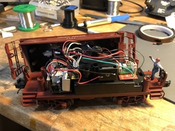
This project implements an idea I’ve been kicking around for a while: to implement Mini-Commander-like TMCC control of an operating car with a compact Arduino paired with a radio module. The arrival of an MTH signalman caboose, which has very little room for additional electronics, provided the opportunity to try it.

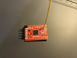
The basic idea is that a master Arduino acts as a bridge, receiving commands from the Legacy base over the serial line and transmitting those commands over the radio link to Arduinos installed in operating cars, which then take whatever action you program into them.  I used the Moteino, which pairs an Arduino with an RFM69HCW radio module. The module can theoretically transmit for more than a kilometer, so should work even on the largest layouts!

IMG_2005

The master Moteino reads commands coming over the serial line from a SER2 module, parses the TMCC command, and, if it’s an ENG or ACC command, sends the command over the RFM69HCW radio to the specific Moteino node identified by the command’s TMCC address.  I use the Radiohead RFM69 library, which provides simple and transparent transmission of addressed, reliable datagrams with acknowledgement and retransmission.

The MTH caboose activates the signalman with a bell detector circuit that responds to the DC offset from the bell button of a conventional transformer; it can’t detect TMCC or DCS bell commands. The MTH implementation is a little peculiar. The bell detector circuit activates a transistor, which delivers half-wave rectified DC from the track to a relay – but instead of activating the relay directly, the DC ( ~ 50 mA) is delivered to a bridge rectifier that feeds a 9V regulator. That 9V regulator turns on the relay. When the relay is closed, it connects power from a separate 9V regulator (which is always connected to track power) to the signalman motor circuit.

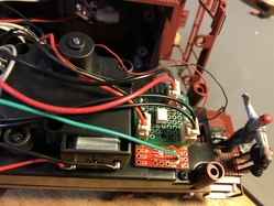
I replaced the bell detector circuit with a Moteino that turns on a small solid-state relay (TLP222AF); when activated the SSR connects track power to the 9V regulator, which in turn activates the relay. It could be done more cheaply with a transistor or triac, but the SSR was only $1 and makes the wiring simple: since the stock MTH circuit feeds a bridge rectifier, I could connect track power directly to the relay control circuit without worrying about rectification. Here’s a couple of photos of the Moteino with a ‘shield’ that has the SSR circuit. I used the existing MTH plugs that connect to the stock bell detector board to connect to my shield.

IMG_2017IMG_2019

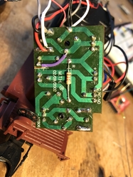
The Moteino needs a source of DC power, of course. The stock MTH board has a 9V regulator that is always connected to track power, even though it only seems to be used when the motor is on. The board even has an unused socket connected to that regulator which I could tap into. However, I found that this plug is only live when the motor relay is active. So I made a small modification to the board, cutting a trace and soldering a connecting wire, which makes the unused socket always live:

IMG_2004

The software on the caboose Moteino is pretty simple. If the Moteino receives a command addressed to it from the master node, it parses the command. If the command is an AUX1 press, then it activates the SSR for 4 seconds, which is enough to initiate the signalman cycle (after 4 seconds, the MTH design activates a microswitch which keeps the motor relay active). I’ve attached the Arduino code for the master and the caboose Moteinos to this post.


The Moteino with a radio transceiver costs $21, so each node in an operating car or accessory could be implemented for less than $25. For installations where there’s no source of DC power available, you’d need a voltage regulator or module to power the Moteino;  it can accept 3.6V to 12V as a raw DC supply and draws about 130 mA at maximum transmission power.

You could make the nodes a little smaller and maybe cheaper by designing a custom PCB with a ‘328 and installing your own RFM69 module, although the convenience of the Moteino is hard to beat.

Since you can also get Arduinos (or other microcontroller modules) with built-in Wifi or Bluetooth, one could probably implement a similar system that gets commands from whatever smartphone app you’re using to control your trains – but I’m still on ‘old-fashioned’ Legacy and the programming for Wifi or Bluetooth is well beyond my skills!

Attachments

Last edited by Professor Chaos
Original Post

Replies sorted oldest to newest

IF I understood your project (it's a big IF!), I think you can also control the MTH Operating Reefer with minor re-wiring but no change in your Moteino code!

prof chaos remote signalman

My $5 modification to an MTH Operating Reefer to make it remote-controllable is described here:

Home-brew remote control of MTH Operating Reefer

I understand the value of re-using the existing cables/connectors in your Signalman project.  But in the case of the Operating Reefer, I chose to make it a 3-wire connection to the MTH electronics with no modification (cutting/jumpering a trace) to the MTH circuit board.

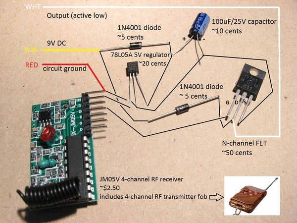
In the MTH Operating Reefer cars, +9V DC is always present on one of the motor terminals (Yellow wire).  Circuit ground is always present on one of the micro-lever switch terminals (Red wire).  And the motor drive trigger is the other motor terminal (White wire).  To trigger the operating reefer to start its cycle, you simply "ground" the White wire for several seconds which is apparently what your single Moteino output can do via the SSR.

Attachments

Images (1)
  • prof chaos remote signalman
Last edited by stan2004

Hi Stan - does that part of the operating reefer just trigger a relay, like in the caboose? The TLP222AF SSR is rated for 500mA, so if that part of the circuit draws less than that it should work fine.

The Moteino's I/O pins can source or sink 10 mA at 3.3V (more if you parallel outputs), so you can use them to drive whatever actuator you want, including PWM. I used the SSR because it made the output circuit trivial, but if you wanted more drive (or didn't want to pony up the $1 for an SSR) you could use a transistor or triac instead.

If I was going to develop this project further, I think I'd design a series of little shield PCBs you could stick onto the Moteino for different applications. E.g.

  • Powered by DC input or added rectifier/regulator circuit for track-powered.
  • Relay, transistor, or triac output.

Being so small (about 1" x 1"), the PCBs would be very cheap.

I'd also design shields for the master node, to read the TMCC commands from a serial line or the Legacy PDI.  Installing the master node is probably the biggest hurdle for someone else to replicate the system, because you need something to read the convert the RS232 to TTL.

Hi Stan - does that part of the operating reefer just trigger a relay, like in the caboose? The TLP222AF SSR is rated for 500mA, so if that part of the circuit draws less than that it should work fine.

In my case, I used a N-FET to directly drive the DC gearmotor.  A photo of the circuit from the linked article:

reefer remote components

As mentioned, in the MTH operating reefer, one side of the DC gearmotor is connected directly to 9V DC.  So the N-FET simple grounds the other motor terminal for a few seconds to start the operating cycles.  My notes show the DC gearmotor draws about 100 mA when active...so 500 mA is good as the long as the SSR is DC-capable.

The Moteino's I/O pins can source or sink 10 mA at 3.3V (more if you parallel outputs), so you can use them to drive whatever actuator you want, including PWM. I used the SSR because it made the output circuit trivial, but if you wanted more drive (or didn't want to pony up the $1 for an SSR) you could use a transistor or triac instead.

Because the Moteino is powered by the 9V from the MTH electronics, I think is safe to assume if driving a DC motor using the MTH electronics, that you do not need the optical isolation provided by the SSR.  Hence I have the RF receiver logic output pin directly driving the N-FET (i.e., no optical isolation).

If I was going to develop this project further, I think I'd design a series of little shield PCBs you could stick onto the Moteino for different applications. E.g.

  • Powered by DC input or added rectifier/regulator circuit for track-powered.
  • Relay, transistor, or triac output.

Being so small (about 1" x 1"), the PCBs would be very cheap.

I'd also design shields for the master node, to read the TMCC commands from a serial line or the Legacy PDI.  Installing the master node is probably the biggest hurdle for someone else to replicate the system, because you need something to read the convert the RS232 to TTL.

Agreed.  The master node is doing a lot more work than the receiver in the caboose!  In my project the trigger is pushing a button on a fob.  But of course that's another device to keep around.  For DCS command control, I separately showed hooking up an output of an MTH AIU to electronically "push" the button on the fob.  So in a TMCC environment I suppose the equivalent would be to have an ASC or SC2 Accessory controller wires to electronically "push" a button on a remote control fob.

Attachments

Images (1)
  • reefer remote components

Of course, you could just use a Lionel R2LC and trigger it with the smoke control triac, it'll do a couple amps momentarily, and about an amp for a longer period of time.  If you have them kicking around, or wait for the Lionel annual sale, they're only $20.  Over the air TMCC and power switching all in one handy board.  You can even add lights and couplers to your creation.

Looking for thoughts on Lionel TMCC R2LC/R4LC

Of course, you could just use a Lionel R2LC and trigger it with the smoke control triac,

Awww, where's the fun in that?

One plus to the custom solution, besides the choice of outputs, is that you can easily program an arbitrarily complex response into your receiver. Like in this application, a single press of AUX1 keeps the relay engaged for the 4 seconds necessary to initiate the cycle.  But it could be more complex - you could, for example, roll your own equivalent to a hot box reefer with sequenced lights, smoke, sound, etc.

Add Reply

Post

OGR Publishing, Inc., 1310 Eastside Centre Ct, Suite 6, Mountain Home, AR 72653
800-980-OGRR (6477)
www.ogaugerr.com

×
×
×
×
Link copied to your clipboard.
×
×