I'm puzzled. My layout is powered by a ZW-L running command mode and each power handle controlled separately running through a TIU.  My layout has two loops connected by switches, and a third elevated loop. Each powered by a separate transformer output: A,C,D. The 2 connected loops are isolated using the Fastrack 1 3/8" track. I removed the wire that bridges the gap in the center rail. It's been working for years.  Then one day the two loops that should be isolated started acting as one.  I've determined the TIU is working properly as is the ZW-L.  Here's what happens. I power up the layout, and as soon as I give power to either A or D (each powering the outer and inner loops) both loops get power. If I have A and D connected and power A, for example both loops are powered and D is also supplying power. If I remove power from D, A supplies power and both loops are powered. I ran continuity checks on the two "block track sections" on one the isolated middle rail shows no continuity...the other shows continuity always.  Does this make sense?  A power block isolation section suddenly becomes "un-isolated?"  The only other thought I had was something is funky with the command switch, but I don't see how that could physically occur. My track is ballasted and other issues make pulling it apart to check a real PITA . I would like to not have to do that if I'm missing something that may be the problem....

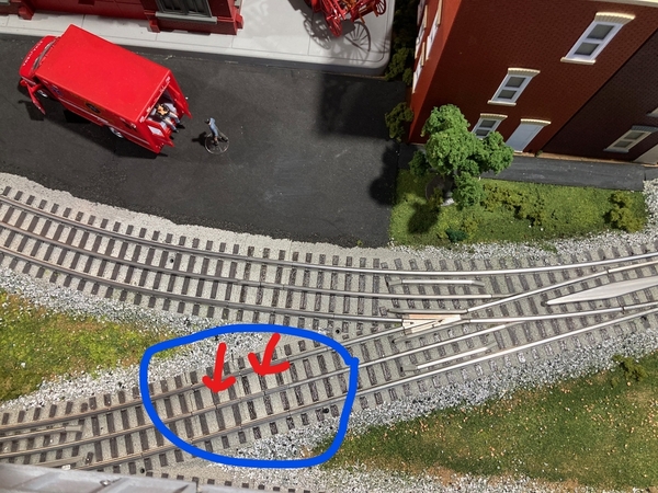
Two sections are shown. One of them isn't behaving...I'm considering just using a Dremel and cut though one of them until the center rail does not have continuity.  The seems easier than removing  ballasted Fastrack and a switch.  Any suggestions/comments welcome.  Thanks.

Inkedswitch

Attachments

Images (1)
  • Inkedswitch
Original Post

Replies sorted oldest to newest

Ed,

There could be another way for those two rail segments to be electrically connected even though they don't appear to be.  As John has suggested a steel filing would be one way but there are others.

I love the term used when we encounter this kind of thing in building pre-production prototype cars -- "sneak path".

You definitely have something sneaky going on here.

Have you checked your wiring for an alternate path from the rail segment on one side of the gap to the one the other?  It might go through a convoluted routing to electrically bridge that gap but not be easily visible.

Any changes in wiring anywhere since it last worked correctly?

Time to start probing, with the power off, between various points using an ohmmeter with a test lead in each of your outstretched arms, looking for an unseen and unexpected short circuit between those rail segments.

Mike

Along Gunrunners lines I think I would take a vacum or shop vac to the gap on the middle rail that you removed the jumper on.  Then if that doesn't resolve it maybe get something small to swipe through that gap to see if there is something bridging the two sides.  If that doesn't work you can at least rule out that piece of the 1 3/8" isolation track.

I can tell you that in my case, I removed the section from the layout and tested it with an ohm meter.  With the jumper removed from the bottom, there was still continuity between the two ends!  How, I don't know but I yanked the pin from one end of an adjacent track, filed back the protruding center rail, and then wrapped it in electrical tape just for good measure.  That solved my problem, but it wasted a lot of time.  So much for "plug-and-play!"

Last edited by Ted S

Well, I've tried all the suggestions regarding the block sections.  Didn't solve the problem.  So the only troubleshooting I've not yet done is, essentially track the buss wires and the drops to see if there is a "sneaky path."  Walt, while I have rewired one accessory, but that was well before this problem showed.  However, I have begun reorganizing the boxes under my layout and it's possible while rummaging around (at 75 I'm not as nimble as I used to be, )  I may have done something. So, next week I'll start the detective process.  Can't wait!  Thanks again fellas for your interest in my problem.  When I figure it out and fix it I'll get back to let you know. 

@ToledoEd posted:

Well, I've tried all the suggestions regarding the block sections.  Didn't solve the problem.  So the only troubleshooting I've not yet done is, essentially track the buss wires and the drops to see if there is a "sneaky path."  Walt, while I have rewired one accessory, but that was well before this problem showed.  However, I have begun reorganizing the boxes under my layout and it's possible while rummaging around (at 75 I'm not as nimble as I used to be, )  I may have done something. So, next week I'll start the detective process.  Can't wait!  Thanks again fellas for your interest in my problem.  When I figure it out and fix it I'll get back to let you know.

I'm sure your detective work will discover a suspect'... and action will be taken'....👍😁

I've returned to this problem.  I started at the beginning...testing continuity. I have 3 loops.

1 is completely isolated no switches.  When I check continuity, the outside rails test positive.  The inside rail has continuity. When I check for continuity between an outside rail and the inner rail, as you would expect, no continuity.

Two loops are connected by switches.  I checked continuity as with the isolated loop and all the outside rails test positive as do the inside rails.  However, when I check for continuity between the outside and inside rail, that also tested positive!  How can that be?  Wouldn't the system short out if the outside and inside rails test positive for continuity or am I misunderstanding the test?  I understand if the block isolation fails I would have power going to both loops, but if the inside and outside loops are connected, wouldn't the system short out????  Help!

In your picture with the blue circle it looks like you have 2 of the 1 3/8” track sections.  If I understand what you said there is continuity across the gap on the center rail in one of the track sections, but no continuity across the center rail gap on the other.  As long as one of the rail sections is not continuous the two loops would be isolated at that point.  Is there somewhere else on the layout where the 2 loops connect through an insulated track section?  If so, maybe that might be where your two loops connect electrically.

If the center rail and the outside rails show electrical continuity that area of the track would be a short.  What are you using to test the continuity?  Can you measure the actual resistance values?  I measured the resistance from center rail to outside rail in the diverging section of a Fastrack O72 switch and get about 5 M ohms.  That is high enough to limit any current to the micro amp level.

Since the trains operate fine on both loops using either A or D and at least one of the two 1 3/8” sections that show in the blue circle is not continuous across the gap, there has to be another electrical path connecting the two loops.  I would start by looking for a place where the 2 loops are joined again by switches.

JFC454; John,  There are only two places where the loops are physically joined.  The picture above is one physical connection where the switch from the inner loop  joins the swatch on the outer loop. That is replicated about 6 ft away where switches physically connects the inner and outer loops.   I removed the switches so there is absolutely no physical track connection between the loops.  (When I power up the loops, the two switches are off, no switch lights)  When I power up the ZW-L and send power to either the outer loop via  the A handle or the inner loop via the D handle, both loops are powered up.  I am using the ZW-L in command control mode, 4 independent controls.  I still get continuity between  (crossing) the outer rails of the inner and outer loops. One lead from the multimeter on the outside track of the outer loop and the other lead to an outside track of the inner loop and get tone...I still get tone when checking continuity between the inner rail and outer rail which I just don't understand.  This happens even when I disconnect either A or D from the tracks.  Bottom line, even when the two loops have physical track connection,  the problem is not the tracks or the switches.  One other operating phenomena: If I power up the tracks with the A output from the Cab2, the D output is also providing power without powering it up from the Cab2.  If I turn the power to "0" on A then both outputs go to 0.  However if I try to reduce power to 0 using the D output from the Cab2 it will not go to 0 but stops at about 15v.  When I start with D and try to lower the voltage on A using the Cab2 it doesn't respond.  Is it possible there is something wrong with the ZW-L as well?

So I guess I can say the power crossover connecting the loops is a "sneak path."?  Is it safe to conclude I'll have to  trace  the bus lines for each loop to try to locate the sneak path? 

Well, it's not clear it's a "problem" so much as a measurement anomaly.  Are you truly getting zero ohms between the rails?

Well, it's not clear it's a "problem" so much as a measurement anomaly.  Are you truly getting zero ohms between the rails?

John, I'm using a Craftsman multimeter. When I check continuity between the outer and inner rails on either loop I get a tone.  Ohms read between 8-13 between inner and outer rails on both loops.

Dan, I removed 2 switches that connect the 2 loops. The manual switch controller does not light, so I assume no power to the switches. I also checked for continuity of the two “block” pieces of track and both read no connectivity in the middle rail as they should. I use them to isolate each loop. I hope that answers your question.

You might try this to see if the problem is with the transformer.  With the ZWL power OFF, change the switches on the back to Run, Conventional (not Command) and 4C.  The power must be off before the switches are set.  THEN turn on the power.  Move the throttle handle on the ZWL for just A to 18 volts and leave the other handles at 0 volts.  Using your meter measure the voltage across the A-U  and D-U terminals on the back of the transformer.  If both A-U and D-U read 18 volts with only 1 throttle set there is probably an issue with the ZWL.  If everything checks out OK try setting throttle D to 18 volts with A set at 0 and measure the voltages at the transformer terminals.  If everything looks normal repeat the test but measure the voltages on the two loops to see if only one loop is powered when only one throttle is set to 18 volts. 

@MartyE posted:

Maybe I'm missing something and late to the game and totally missing something but any chance this switch is in 1 channel mode?

ZW SWITCH

Marty,

No it is in 4 ch mode. I even unplugged the transformer and reprogrammed per the manual for command control and 4 ch. operation.  I have a third loop running off of the C output that is completely isolated from the other loops and operates as you would expect.

@JFC454 posted:

You might try this to see if the problem is with the transformer.  With the ZWL power OFF, change the switches on the back to Run, Conventional (not Command) and 4C.  The power must be off before the switches are set.  THEN turn on the power.  Move the throttle handle on the ZWL for just A to 18 volts and leave the other handles at 0 volts.  Using your meter measure the voltage across the A-U  and D-U terminals on the back of the transformer.  If both A-U and D-U read 18 volts with only 1 throttle set there is probably an issue with the ZWL.  If everything checks out OK try setting throttle D to 18 volts with A set at 0 and measure the voltages at the transformer terminals.  If everything looks normal repeat the test but measure the voltages on the two loops to see if only one loop is powered when only one throttle is set to 18 volts.

Here's what I did:

1. set ZW to conventional and all A-D power to 0

2.Powered up A to 18v.   D read 15+ despite the handle set to 0

3. Reversed 2 above. D to 18V.  A read 16+ despite being set to 0

4. I set all handles to 0. Powered up A to 18v.  Both loops registered about 16+ volts.

If the ZW-L has a problem, I still don't understand how I get continuity/ohms registering between the outside and middle rails on two loops.  The third loop, isolated from the problem 2 tests correctly.  The continuity reading between the loops happens even when I physically detach the power leads to the loops.

Just spoke to Lionel Customer Service.  They said it's probably a capacitor. They assigned an RA number so I'll be shipping the beast back to them.  I bought this in July of 2011.  They are going to repair it as a 'courtesy repair'.   Great customer service!!!

Now, I have two PW ZW's, any issues if I hook one of those up in it's place?  I have quick blow fuses protecting the loops.

@ToledoEd posted:

Here's what I did:

1. set ZW to conventional and all A-D power to 0

2.Powered up A to 18v.   D read 15+ despite the handle set to 0


When A is set to 18 v, is the 15 volts the reading on the ZWL’s meter for D or is it the voltage measured on the loop?  I would think if it is the ZWL’s meter then there is a problem with the transformer.  If it is measured across the rails in both loops then something is connecting the loops.  

Well, I'm confused.  You disconnected the transformer entirely from the layout and still had continuity between the rails, how can that be the transformer???  It's nowhere in the picture!

John, I probably contributed to the confusion.

Two separate issues presented.

1. Continuity:  Continuity between loops and between inner and outer rails.  This exists whether the transformer is attached or not.  You are correct, the transformer is not the source of this issue.  I removed the only physical connection between the loops, the two switches, but the cross, goofy continuity continues.  I guess I need to trace the bus lines and drops to see if somehow they got crossed?  I did notice that I was getting voltage from A and D even when one was set at 0 but it didn't click with me as an issue.  Maybe because the ZW-L was set in Command mode and I just overlooked the problem. (Age. That's my story and I'm sticking to it. ) 

2. ZW-L not operating properly, (Originally I thought maybe the ZW was contributing to the continuity issues. It wasn't)    When @JFC454 posted a suggested test of the ZW-L I realized something was clearly wrong. Lionel customer service diagnosed the problem as a "bad capacitor" in the ZW-L. Fortunately Lionel will repair the ZW-L at no cost to me.  Now I have to find the product box and shipping box...somewhere in my garage overhead storage with 90+ degree weather outside.  Oh, so much fun!     Then continue my search for the cause of the strange continuity issues.  I just don't understand how I can get a positive continuity reading between the outside rails and the innerrails yet not have a short?

@JFC454 posted:

When A is set to 18 v, is the 15 volts the reading on the ZWL’s meter for D or is it the voltage measured on the loop?  I would think if it is the ZWL’s meter then there is a problem with the transformer.  If it is measured across the rails in both loops then something is connecting the loops.  

I took the readings at the A and D output terminals on the ZW-L.  The voltage was only displayed on the meter of the the handle that was actually used to power up to 18v,  Yes, it does read across both loops. I think the only explanation left is what you identified "something is connecting the loops)

If the D throttle is off and it’s meter is reading 0 volts that doesn’t indicate a problem with the transformer.  If there is an electrical connection between the 2 loops you would read A’s voltage across D’s terminals even with D’s throttle off.  I would probably hold off sending the transformer back until I found the continuity problem in the track.

One I thing I might suggest is to remove all power connections to the transformer and then connect the elevated loop that you know is isolated to the A throttle instead of the C throttle and see if it works OK.  Then disconnect A and try running the isolated loop using the D throttle.  If everything works OK I would not think the problem was the transformer.

@JFC454 posted:

You might try this to see if the problem is with the transformer.  With the ZWL power OFF, change the switches on the back to Run, Conventional (not Command) and 4C.  The power must be off before the switches are set.  THEN turn on the power.  Move the throttle handle on the ZWL for just A to 18 volts and leave the other handles at 0 volts.  Using your meter measure the voltage across the A-U  and D-U terminals on the back of the transformer.  If both A-U and D-U read 18 volts with only 1 throttle set there is probably an issue with the ZWL.  

What I wrote here is not correct if the transformer is still connected to the 2 loops that are not really isolated.  Measured across the output terminals both A-U and D-U would read about the same voltage if just one throttle was set to 18 v.

@JFC454 posted:

What I wrote here is not correct if the transformer is still connected to the 2 loops that are not really isolated.  Measured across the output terminals both A-U and D-U would read about the same voltage if just one throttle was set to 18 v.

Rod and @JFC454, I redid my testing and, sure enough, I did the voltage checks on the ZW-L with the two loops connected.  When I disconnected the loops, the ZW-L  operated as it should.  It's not the problem.  Thanks for the help.  I don't know why/how I got this so wrong earlier.

@walt rapp posted:

I like @Mellow Hudson Mike 's idea as possible.  Did you do any rewiring recently after your last successful 'proof'?  Could you somehow have a wire connecting both loops?  Even if it's thru a junction.

walt

Mike and Walt, I did not rewire intentionally.  But after all the testing and removing the switches, the only 'rewiring' that could have occured was accidently and unwittingly when I spent a week rummaging around under my layout to get some order to the boxes...I ended up getting everything, well mostly, into storage bins that I cataloged using an inventory app called "ToteScan".  Very cool.  I think maybe I did something at that time.   

I'm going to trace the bus lines for those two loops and hope I discover whatever is providing a path to link the two loops. I know it's the track, and it's not the transformer so it must be something under the layout.

@JFC454 posted:

What I wrote here is not correct if the transformer is still connected to the 2 loops that are not really isolated.  Measured across the output terminals both A-U and D-U would read about the same voltage if just one throttle was set to 18 v.

Thanks. In response to your comment I went through all the steps regarding power and the ZW-L but with the leads to the loops disconnected. As you said, the ZW-L responded as designed. With loops disconnected, power to A did not result in any power from D and vice-versa.  So, it's not the transformer or the TIU.

The outputs respond correctly whether in command or conventional mode when the connected loops are not connected to the transformer.  The additional good news is I was able to dig out the ZW-L box from the overhead garage storage! 

If the switches and transformer are both disconnected, what is still connected to the track?  Clearly, something is still connected!

John, I disconnected every power source to the layout, even a wall wart I use to light some under the upper level track.  No connections at all.  I then tested continuity as before,  I still get a tone for continuity along each individual inner and outer rail as well as between inner and outer rails in each loop and across loops.  Clearly they must be connected somehow.  Ohms reading are, less than 1 ohm when testing each individual rail, inner and outer, but ohms of about 3-8 when I place a test lead on the inner rail and the other on the outer rail.  Less than one ohm registers around the individual outside rails.  (The 3rd loop that is completely isolated w/o issues shows about the same ohms .5 or less along each out rail and the inner rail. No continuity tone or ohms register when leads are on the inner and out rails)   I have 3 accessories connected to the loops. A signal bridge activated by a Lionel 153 IR Controller; lights for a gas station; and a string of LEDs. 

Add Reply

Post

OGR Publishing, Inc., 1310 Eastside Centre Ct, Suite 6, Mountain Home, AR 72653
800-980-OGRR (6477)
www.ogaugerr.com

×
×
×
×
Link copied to your clipboard.
×
×