DISCLAIMER:  I am not breaking substantial new ground here, but this post might be helpful to those who have never tried this before

I decided to embark on a campaign to upgrade the ends of my fleet of Golden Gate Depot Passenger cars.  So far I have completed two. As I have 30+ cars, and I don’t plan on doing this non-stop, I expect this to take awhile

Here are two cars, one before (left) and one after:

3680

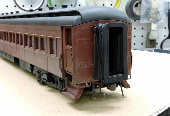
I added the following

  1. Scale City (ex Keil Line) diaphragms
  2. Precision Scale (PSC) Air hoses
  3. Precision Scale BARCO steam connectors
  4. Cut levers
  5. PRR style “bulls eye” marker lights (only to the end cars on each train)

This work goes much easier if you separate the ends from the cars.  Fortunately its quite easy.  Just remove the two screws just to the left of the coupler box:

3686

The ends are registered by pins that go into the bottom lip of the roof. So, when the screws are out, just pull the end up and rotate the bottom it slightly outward

To install the diaphragms, I pretty much followed the instructions. Which, I trust Marty won’t mind, if I post them here

36833684


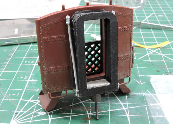
I needed to modify the striker plate and threshold casting to fit the GGD P70s.

3673

The upper part of the striker plate was cut flat and the corners rounded in order to make them more Pennsy like.

The lower cross bar of the of the striker was made thinner to clear the Kadee coupler box.  This necessitates making the threshold casting shorter. I cut out a section with a UMM UMM P100 saw.  I have discussed these in an earlier post. These are very thin, very fine teeth saws that cut remarkably straight and fast.  They look like this:

3626

You can get them from UMM-USA:

http://umm-usa.com/onlinestore...o.php?products_id=35

Use soap as a lubricant every few passes.

Note I scuffed the plate for better paint/glue adhesion. Here is the back side of the striker plate with the threshold held in place with Goo and Zap-A-Gap thick CA. (apply the Goo to both surfaces, wait two minutes, apply drops of the CA to one surface, then press the pieces together.)

3674

I assembled the support bars to the threshold plate per the instructions.  So they look like this:

3682


 A  word of caution: the section of the support bars which has the cast in thread is weak, and can’t take too many bends before it breaks.  So don’t keep trying to straighten it.  Live with it crooked until the final installation. (If you do break it, it can be repaired with a drop of Zap-A-Gap at the ends, apply accelerator, and then apply a sheath of JB Kwik Weld  around the joint.  But now, of course that exquisite thread detail is lost)

 I then painted the assembly with Rustoleum Dark Gray Primer followed with mist coats of Rustoleum Weathered Wood.  I painted the diaphragms with the same combination; Dark gray primer but with a heavier coat of weathered wood.

3675

The painted one is on the left (DUH!)

The instructions recommend GOO to attach the diaphragms. I used adhesive transfer tape (Chooch #8249 is one of many brands) because it’s far less messy, and can be easily removed if needed.  It’s basically an ultra thin, very strong two sided tape.  I attach the diaphragm first to the striker (not shown) and then to the car end:

3676

Ignore the fact that the tape on one leg is white, the other two yellow.  The removable paper is different on the two sides of the sheet.

Here it is attached to the car. For clarity I did not paint the support rod/striker plate/threshold assembly prior to assembly on this one.   

3677

I decided not to add the leaf spring on top of the diaphragm.  Scale City offers a very nice casting, but it is non functional, and hence would compromise operation around curves.  I tried a thin piece of brass to simulate the spring, like Precision Scale or Pac Limited does, but I could not get it to both look realistic and allow smooth operation.  Basically it prevents the diaphragm from compressing uniformly in curves. Besides, its tough to attach to the striker in the confined space above the “Pennsy-zed” striker. So no upper spring

The PSC air hoses, BARCO steam lines, and ersatz cut lever were attached by drilling holes on the underside of the end. The cut lever is made from .020” phosphor bronze (available from Tichy Train Group) and is held in place with PSC eye bolts.

3678

The PRR Bulls Eye marker lights are made from Tower LEDs, and their construction is described in detail in an earlier post:

https://ogrforum.ogaugerr.com/...s-on-ggd-p70-coaches

Of course, the two big questions are

1) How much do these close the gap,

2) How much do these compromise operation. 

The answers are

1): Completely. My O Scale passengers no longer have to do the flying broad jump to get between cars

3685


2):  Not at all. These cars go around the same 44” radius curves they always did. They would probably go around something tighter.

The learning curve here was rather shallow, and if I went into batch mode (two cars at a time) I estimate it would take three hours to do two cars. Excluding the lit markers, which are only going on end cars.  

And of course, they do look better:

3679


Attachments

Images (14)
  • 3680
  • 3686
  • 3683
  • 3684
  • 3673
  • 3626
  • 3674
  • 3682
  • 3675
  • 3676
  • 3677
  • 3678
  • 3685
  • 3679
Last edited by John Sethian
Original Post

Replies sorted oldest to newest

Very well done Master Sethian.

My quick and dirty interim fix for the blob diaphragms on my GGD P70's was to use Weaver diaphragms. The same as on their B60 baggage cars. Nicer detail until I can get to the mountain of K-L diaphragm kits I have in queue.

one word though: the Weaver parts are stiffer

your work looks a lot nicer.

Neat;

If you can give me some dimensions I'd like to try to make everything except the diaphragms as a 3D print.

I can print the striker plate,  the support bars and threshold plate. I can add attachment for the diaphragm to the back of the striker plate to help align the diaphragm. I won't need the bottom cotter pin as the support bar will have an integral and movable bolt. 

Let me know. 

Last edited by AlanRail

Your work looks great, very nice! I also was unaware of the UMM site and marked it for further investigation. Just finding the parts (and tools) and figuring what would be needed for a project like this is a big challenge for me!

Also, just a FYI, I noticed the thread about the marker lights is closed. Looks like this may have been one that got closed unintentionally a while back when a forum setting was changed. I didn't see anything that looked out of line in the thread (but I am not a moderator). Anyway, if you would like it reopened to allow further discussion, the moderators will do that if you notify them and include a link to the thread. Not sure if you knew about that or not and thought I would mention it just in case?

Great work John! These are the best looking and functioning diaphragms I've ever seen. I always wondered if the plates could be made from the plastic magnetic material used in refrigerator magnets. That would hold the two adjoining diaphragms together, assuming there was enough diaphragm flexibility to avoid pulling the following car into a derailment.

Again, an outstanding job! Thanks for sharing the how-to.

Last edited by Trainfun

JOHN SETHIAN     THANK YOU FOR THE POST ANOTHER FANTASTIC TUTORIAL AS USUAL!!!!!!!!!!!!!!!!!!!!!!!!!! Send me the specs for the   striker and we will laser cut these.

SANTIAGO there is an alternative we also make a steam connection for $6.00 pair currently not on the website just email us.

For further info we are working with Dan Pantera of Calumet to redesign the strikers for all the different style that were made so that you can have a prototypicaly correct striker for your passenger cars.

AGHRMATT you can cut these bellows down a little if you want to make them a little shorter so that they will work on tighter radius. If you would like to try that order 1 set and we will throw in an extra diaphragm bellows so you can experiment.

Thanks everyone!  Its always good to get encouragement from your peers!. In answer to some questions:

Marty and AlanNH, Here is a drawing of the striker as I modified it:

3687

Marty

I'd like to pick up a a couple of sets of your steam lines, as well as two additional sets of the 48-024 diaphragm sets at The Strasburg Show.  Also, is it possible to get the support rods separately?  That way I can have spares if (when) I break them

Matt

I think these will work fine around a 36" radius,  The diaphragms are quite flexible. The only thing that might trip you up is the thresholds might hit the end of the car body.  In normal operation they end about 3/16" from the end.  If that is the case, you can file chamfers into the threshold.  By the way, I assume you are using kadees. If you are using three rail couplers, the diaphragms would have to be much longer..even an extra fold.

Trainfun

You don't want magnets to hold the striker plates together as they need to freely slide across one another to smoothly negotiate curves.  The reason these work so well is the diaphragms are made of a very flexible material and are very lightly compressed (if at all) when the cars are coupled together.  Thus, when the cars go around curves the diaphragms compress easily.  To do that, they must also slide with respect to one another

Chris (aka John Galt, aka PRR man).  

Yeah, I am not into heavy weathering.  As you know the PRR kept its equipment pretty clean in my modeling era of the mid 50's. Now a dozen years later, dirt was the the standard for the standard of the world


Attachments

Images (1)
  • 3687
John Sethian posted:
...

Matt

I think these will work fine around a 36" radius,  The diaphragms are quite flexible. The only thing that might trip you up is the thresholds might hit the end of the car body.  In normal operation they end about 3/16" from the end.  If that is the case, you can file chamfers into the threshold.  By the way, I assume you are using kadees. If you are using three rail couplers, the diaphragms would have to be much longer..even an extra fold.

...


Thanks for the info. Much to the dismay of some of the other club members, I've been switching equipment over to Kadees and scale wheels. Even with the long-shank Kadees, passenger cars look like they'd couple closer than with the hi-rail couplers.

what i would do is 3D print both strikers connected with both rods at the thresh-plate. paint it, then you would insert the bellows diaphragm between the plates with a clip or depression in the plates to align them.

then attach the assembly to the car frame.  further,  i am thinking that each assembly has a male/female connector to link each assembly from car to car. 

how thick are the striker plates you need to think 3D.

i'll post the .stl files so you can print them or the Rhino 5 model file so you can modify them.

Last edited by AlanRail

Nice work John and thanks again for sharing.  Closing the air gap between passenger cars with working diaphragms is a major step forward. 

Dan Pantera of Calumet Shops has been using Keil Line (now Scale City Designs) diaphragms when up detailing passenger cars for years - but to repeat a word of caution about the white metal cast support rods.  I've had several break on finely detailed Calumet cars in the thin threaded area despite careful handling.   In response  Calumet Shops now uses virtually identical lost wax brass support rods in lieu of white metal ones on their custom models. 

Marty - I'd like to see Scale City Designs offer brass ones in their diaphragm kit even if it meant a slight price increase.

Keystoned Ed posted:


....Marty - I'd like to see Scale City Designs offer brass ones in their diaphragm kit even if it meant a slight price increase.

Good point Ed.   Alternatively, cast the support rods around a length of .025" phosphor bronze wire

AlanRail posted:

....

how thick are the striker plates you need to think 3D.

Alan

They are about .040" thick. I suggest you buy a set from Scale City, that would be a more accurate way for you to get dimensions. 


Guys,

Just to hit a few high points. They are thin where the threads are and demand careful handling, John Keil designed these to have extreme detailing. They are  more detailed than any of the precision scale verisions I have on my precision cars. There is absolutely no way to cast these around a wire. It is a good thought but what will support the wire in the center of the mold. Plus the threaded part is only .033 so even if you could get .025 wire exactly in the center of the mold, that will only give .008 or .004 (thickness of 1.5 sheets of copy paper) on each side of the wire which will be impossible to get metal to flow. Even if it was possible once they are bent instead of breaking, the metal being that thin would just flake off exposing the wire. Trust me I have tried everything possible. Even expermineted with harder metals which cause them to break easier. I have only shipped these using the exact same mixture from same manufacture as the keils did since the early 80s. The only thing to do is redesign without the threaded part, but when I have mentioned that to a few o scalers they got a sour look on their face. Which I agree the detail is awesome that it adds. I have contacted 3 places to cast in brass. 2 told me they dont have time and were not interested and 1 my cost for 4 rods well exceeded what I charge for the whole kit. Trust me I am not upset and am using your contrustive information provided to help better the line. However if you guys think these are not good I will consider just discontinuing them as I don't want to sell a bad product. I know the redesign eliminating the threads would solve the issues, but will it eliminate the demand? I could also make them a little overscale at the threads which would eliminate issues too, but again most people using this version are true o scalers so will that upset the mass of them as well? Whats your opinions?

Ed, I have also seen those brass versions out there which look identical to ours. I don't know who copied the design, but it is sad to see. Alan, instead of trying to copy what we have paid for why not do the extensive research that Mr Keil did when he designed. The information is out there obviously as Mr Keil found it, but just reverse engineering something we already sell really is the wrong direction for this hobby in my opinion. I have been in many businesses through my years, but model railroading seems to be the only one that everything on the market is just fair game to whoever wants to copy or reverse engineer. Then we wonder why no one wants to invest the time to bring new products to market. I came out with a welder just before the chicago show and I see someone who will remain nameless has added to their line already. I mean seriously that's demoralizing...


Marty. I have purchased twenty or more Keil Line diaphragm sets over the years. I appreciate their good looks.   My personal preference would be to pay more for lost wax brass support rods - or absent that option offer white metal rods that are the full thickness top to bottom. Repairing broken rods on finished cars is a downer


John,

Thanks for the "tutorial"!  I bought some of the early versions of the Scale City diaphragms, was frustrated by the lack of instructions and not being able to fold the fabric and gave up.  Since then, I've used the striker plates on both Atlas and MTH rubber diaphragms which improves the looks markedly.

I'm in the midst of modifying a MTH 70' streamlined baggage car to represent a Great Western 80 series car.  Having Kadeed the car, trimmed the factory diaphragm back to 2 folds & 3 ribs, and applied the striker plates, I'm ready to dive in with the hardware, to the extent that I can do so.

Examining the beautifully reproduced side stabilizing rods and recognizing their fragility, it occurred to me that bronze might be the better material, rather than white metal or brass... if feasible.

I see that Marty now pre-folds the diaphragm material and I presume he also includes instructions.  I'm just grateful that he has taken on the product lines that would otherwise have disappeared!

AlanRail posted:

Neat;

If you can give me some dimensions I'd like to try to make everything except the diaphragms as a 3D print.

I can print the striker plate,  the support bars and threshold plate. I can add attachment for the diaphragm to the back of the striker plate to help align the diaphragm. I won't need the bottom cotter pin as the support bar will have an integral and movable bolt. 

Let me know. 

Fwiw, I would be interested in the "bugeye" marker lite casings printed in 3d. 

Add Reply

Post

OGR Publishing, Inc., 1310 Eastside Centre Ct, Suite 6, Mountain Home, AR 72653
800-980-OGRR (6477)
www.ogaugerr.com

×
×
×
×
Link copied to your clipboard.
×
×