I will be the first to admit that this project is totally out of left field. It has very little to do with Model Railroading. BUT…..
As soon as I saw the Woodland Scenics “Smith Bros Television and Appliance” store with its back lit TV screens, I knew I needed to get one and modify the TVs.
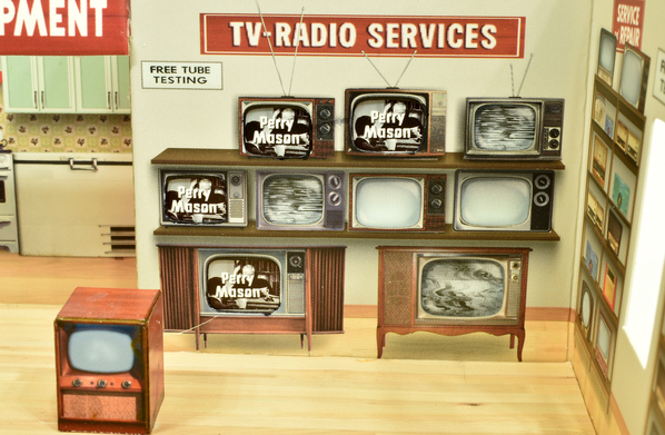
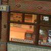
This is what the original building looks like. For those unfamiliar with this building, appliances are on the left and TV’s are on the right. Some of the TV’s have backlit images to simulate a working TV. The images are all the same, and largely illegible:
This is what I finished with
The floor and walls are now straight. The models of the appliances and TV’s are much better. And the TV images are from the original Perry Mason TV series “Case of the Restless Redhead”. (More on that further down this post.) Here is a close up of the TV section of the store:
My original goal was just to change the TV images. However, I soon discovered that I am not satisfied with several aspects of this building:
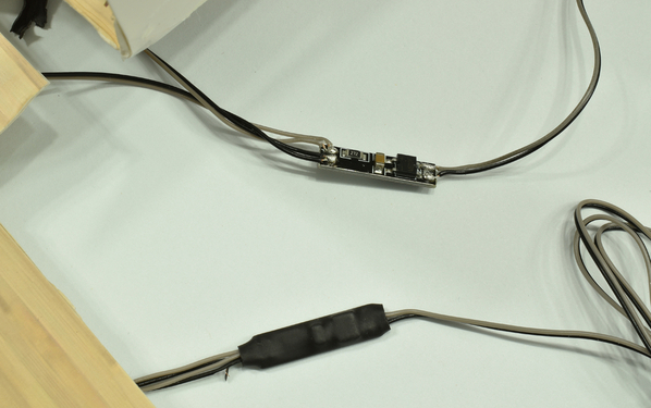
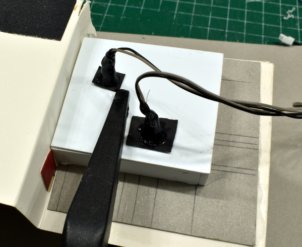
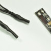
1) The TV’s flicker. I guess this is to give the impression of a moving picture, but I found it distracting and annoying. To get rid of the flicker, I bypassed the small circuit board in the TV LED wiring. There are two such boards, one for the array of LEDs that light the TVs in the wall, the other for the array that light the free standing TVs
This is the circuit board protected by heat shrink tubing (lower) and with the tubing cut away:
This is what it looks like bypassing the circuit board. Make sure you keep the polarity the same (gray wire connects to gray, black wire to black)
2) The original floors, walls, 3D appliances, and TVs are simply printed cardstock that has been folded into boxes. That in itself is not a problem, but the cardstock is flimsy, the folds are not crisp, nothing is square, and the TV’s and appliances do not sit flat on the floor. You can see everything is crooked in this view:
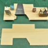
To take care of the floors, I cut the existing floor from the walls, and used 3M #410 Double Stick Tape to hold the floor to a new subfloor made from 3/32” basswood
5387
I then attached the walls individually to the floor, making sure they are square and level.
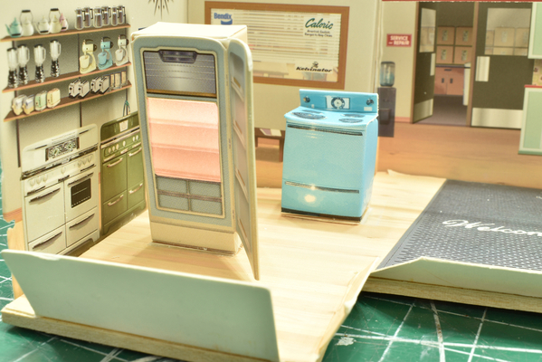
3) The free standing appliances are not very well done. This is a view of the original open refrigerator and stove.
5388
The refrigerator is tilted to one side, has a crooked door and deformed top, and has shelves printed on a flat piece of semi transparent plastic and backlit with an LED. The stove looks likes it has been dropped several times. It is really obvious both stove and refrigerator were made by a second grader folding up pre-printed card stock. However the printed walls look pretty good.
I would have dispensed with the refrigerator altogether, but there needs to be an open lit something in that spot for visual balance. So I made a new refrigerator and stove from styrene strips. The open refrigerator has transparent shelves so the the interior is lit. I also added a second refrigerator. I painted the first one almond, the second and the stove French Blue, as those were popular kitchen appliance color at the time:
I used the same original LED in this refrigerator. The refrigerator handle on the open refrigerator is a door handle from a 1/43 Aston Martin DB5 I had lying around. The door handles on the second refrigerator are from the windshield wipers off the same car. The stove handle is a drop grab iron, the cooking tops are brake wheels, and the center control is a cut down EMD speed recorder. Talk about repurposing!
Now on to the TVs. Let’s start with the ones in the back wall: There are four TV apertures, each with its own TV image. The images are printed on a semi transparent thin plastic sheet which is glued to the back of the wall. Two of the screens are back lit by one LED, the other two by another. The LED’s are held to the back of a trapezoidal folded shadow box made from black construction paper. The front of the box is glued to the back of the wall.
These shadow boxes are not the best design: The black absorbs light, so the net effect is to have a single point source of light backlighting the screens. As a result the screen lighting is not uniform. Another problem is the folded construction paper box is not rigid, and it is tough to remove and reposition after being removed.
Remove both shadowboxes and both image films. Be careful here, you don’t want to tear the back wall or distort the TV apertures. Use a sharp #11 blade to assist. You can cut up or tear the shadowboxes as much as you need to remove them. The only thing you want to keep is the back face of the shadowbox that has the LED.
Now you are ready to select and make your TV images. I used a Perry Mason DVD in my computer. You can use any digital image. Here is what I did:
- Watch the DVD.
- Still the frame you want to capture
- Press “Shift” Print Screen
- Open up Adobe Photoshop
- Paste the image into Photoshop (use “New From Clipboard”)
- Crop the image so just the TV image shows
- Change contrast to “+55,” so the contrast is dramatically increased
- Change the resolution to 600 dpi
- Resize image to 1.4 cm wide. Or whatever you need to fit your TV opening. Constrain the proportions so the height remains correct
- Save image as a Tagged Image Format (.TIF) file. Avoid compressed files such as jpg
- When you are ready to print, Print on HP Premium “Glossy Paper.” Do not use photo papers, as their relatively thick and slightly rough backing compromised image quality. Set the printer for glossy papers, and at highest resolution.
Test to make sure the TV image fits in the apertures in the back wall. Cut out the image, leaving a ¼” frame. Use double sided scotch tape to hold the image in place. Work carefully so the image is properly aligned in the TV opening. Repeat for the other three images. When done you will have this:
The non functionning TV is in the foregroun. As noted earlier, the cardboard Woodland Scenics used for the walls is a bit flimsy. It is also translucent, so you loose the dramatic contrast with the TV screens. I solved that by adding an opaque cardboard mask to the backside. The lines you see are to guide cutting the mask to exactly fit the TV openings. The mask is glued with Ailene’s Tacky Glue:
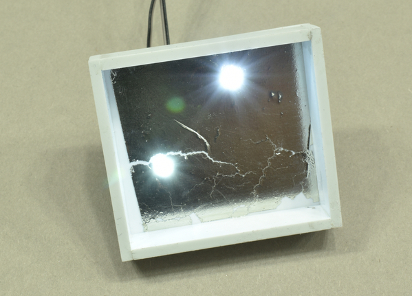
I made a single light box from styrene strip and sheet, and added a foil reflector to the inside:
Each LEDs is positioned to light two TV’s. I glued the box to the backside of the cardboard mask with Ailene’s. I added a piece of wax paper between the shadowbox and the cardboard mask in order to diffuse the light and get more uniform illumination of the screens. Ignore the clamp in the photo, it gets removed after the glue dries
The black rectangles you see are all that’s left of the folded construction paper shadowboxes that originally held the LEDs. At this point, the wall is done.
The stand alone TV’s are a bit more complicated. I trashed the Woodland Scenics folded cardboard TVs. I made one non functioning TV, one console TV, and a TV array with six screens. The console TV and array are glued together. All TVs are made by printing an image of a TV on HP “Soft Gloss” paper, and then attaching that image to a box. The front, sides and top are glued separately as decribed below.
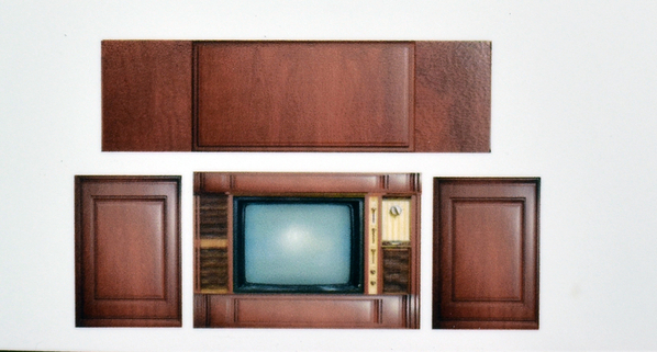
To get the image of the TVs do a Google Search of “Vintage TVs” You can add your era in the search. I don’t want some neurotically obsessive “Vacuum Tube Pin Counter” saying my TVs did not exist in the era of my layout. Get an image that is square on to the front of the TV. Using Adobe PhotoShop, or some similar software, create an image of the TV front, sides, and top and print it on HP Soft Gloss paper, or equivalent:
In this case I made the sides and top from Google Images of “wood paneling”. I changed the shape of the panels to fit the top and side. I added a top and bottom to the face of the TV using the same panels, to make everything blend in. Note the sides and top are not connected. This is because you will apply them separately to the underlying styrene (or wood) box. Note also the top is considerable wider than the TV front.
For the non functioning TV, the box was a length of ½ x ½ bass wood. For the other two the box was made from styrene: For the console TV I used 0.412 x .100” styrene strips. The width of the box should be slightly less (about 2 mm) than the width of the TV you created in Photoshop. The height should be 2mm less as well. The depth should be the same as the depth of your printed TV top. Make sure the box is dead square, then hold it together with styrene solvent cement:
To install the front with the TV image, refer to the photo below
- Cut out the front of your printed TV.
- Attach a piece of foil to the backside. The foil is to serve as a light block around the TV Aperture. I used Matte Aluminum Bare Metal Foil, but you could use regular aluminum foil attached with 3M 77 spray glue. The Bare Metal Foil is easier to attach smoothly and to cut.
- From the front of the TV Face, cut out the picture tube. Use a fresh very sharp #11 blade. Use a scalpel if you have one. Make sure you go all the way through to the foil. Don’t get obsessed with following the curvature of the tube. This job is difficult enough as it is, and its tough to get a nice sharp aperture.
- Using the TV Image, make sure it has a “frame” that exceeds that of the TV front. Then attach it to the backside of the TV face using double sided Scotch Tape, or better yet, transfer adhesive tape. Obviously you need to align the image with the TV aperture. When you are done, trim the excess of the image frame to match the TV front.
Glue the TV front to the front of the styrene box. Try to have the sides and top of the face stick out about 2 mm. The bottom of the face should be even with the bottom of the box. I used Ailene’s tacky glue, but most anything similar will work. Just be sure you have a thin uniform layer of glue, and clamp it between two flat surfaces until the glue fully sets. Overnight is suggested. Then glue on the top. The front of the top should butt against the backside of the face. Note the ends of the top stick out quite a bit:
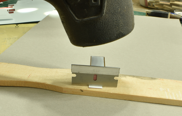
After the glue is cured, glue on the two sides. The sides should butt up against the underside of the top and the backside of the front piece. Next trim the top and front so their ends are flush with the sides. Use fresh sharp single edge razor blade, align it against the side, and rap it with a hammer:
Trim in the following order:
- Front where it meets the top
- Top where it meets the sides
- Front where it meets the side.
Color all the exposed edges with artist marker, such as a Tombow ADT Dual Brush Alcohol based marker. I get these at our local Plaza Artist Supply store. I have found the staff there to be very helpful in matching your image color with these markers. Just take your image in with you. Alternatively, buy several which closely match and pick the best one when you get to your workbench.
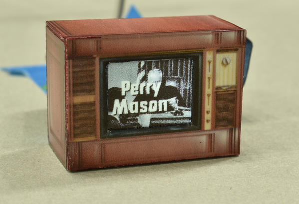
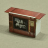
When you are all done, you should have a reasonable O Scale Stand in for a vintage console TV:
If the image looks a bit fuzzy, remember there were no HD TV’s in 1956!
Construction of the TV array follows much the same technique as the single TV. In fact, I glued them together as one unit. Here is the backside, showing where the LEDs are located:
And here is the front of the Console/TV array.
And now, an explanation of the images I chose:
I am a very big fan of the Perry Mason TV series, and no matter what I have planned for the day, I spend an hour each morning watching Perry Mason while I work on the railroad. Yes, I know they are shortened to make room for all those obnoxious Car Shield, Liberty Mutual, and Medicare Advantage ads, but as I have seen all the full length episodes several times on my DVD collection, and I am not really watching anyway, it’s just fine with me.
I chose scenes from “The Case of the Restless Redhead” for my TVs. This was the first episode broadcast. (The pilot was “The Case of the Moth Eaten Mink” and was shown eighth.)
The console shows the opening frame, where Perry says something to a judge. Next is the second frame naming Raymond Burr as the star, as he slyly smiles to himself. The third is the title of the episode. This episode is based on one of the 82 Erle Stanley Gardner books. They are generally better episodes. There were 271 total. The fourth image (second row, left side) shows the supporting cast: Della Street (Barbara Hale), William Hopper (Paul Drake), William Talman (Hamilton Burger) and Ray Collins (Arthur Tragg). The fifth image is the lovely but distressed Evelyn Bagby (Whitney Blake) in full panic on the phone to Perry. The sixth shows the mysterious pillow case-shrouded stranger who tried to run Evelyn off the road. And the final image is of the nefarious Mr. Boles (Vaughan Taylor) who Perry breaks down on the witness stand.
I told you this has nothing to do with Model Railroading. I shall now return to erecting catenary


