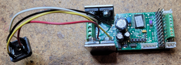
Recently, there have been a few discussions about running A-A configurations with two powered units and four motors with the Cruise Commander.  It is alleged by no less than the man that designed the Cruise Commander, Jon Z., that the major issue that might compromise this issue is overheating of the bridge rectifier. Apparently, this degrades the rectifier and increases the leakage currents through it enough that it compromises the FET drivers and subsequently kills them.  Obviously, we want to prevent this!

I also note that the MTH boards actually heatsink the rectifier and not the driver FET's, that seems to make a lot of sense based on this information.  Also, a number of larger Lionel locomotives have a DCDS that also has a tethered bridge that is bolted to the frame for heatsinking.  It would have been nice if the Cruise Commander had mounted the bridge under the PCB and secured it to the heatsink as well, but we can't have everything.

Given this large body of evidence about keeping the bridge cool, I decided to modify the Cruise Commander that I'm installing in an A-A configuration with both units powered to give it a tethered bridge.

ERR Cruise Commander with Tethered Bridge

The hardest part of the job was getting the bridge off the board without damaging the board.  The bridge actually manages to dissipate quite a bit of heat from the leads, apparently by design.  Given that the Rectron BR84 8A bridge is only 99 cents, I decided that it wasn't worth trying to save the old bridge rectifier for the piddling amount of money it costs for a new one.  I ended up removing the driver FET heatsink and folding the driver FET's out flat.  Then using the Dremel tool I chopped up the bridge to remove it so I didn't damage the PCB.  It was then easy to remove the remaining leads and solder my jumpers from the replacement bridge to the PCB to complete the job.

The bridge will be bolted to the chassis with heatsink compound and a flat washer on top to maximize heat transfer.

Attachments

Images (1)
  • ERR Cruise Commander with Tethered Bridge
Last edited by gunrunnerjohn
Original Post

Replies sorted oldest to newest

I'm driving all the motors with one CC, they will all be wired in parallel.  I've never bothered to do this for one or two motors.  This came out of a conversation about this topic where Jon Z. chimed in and explained that the bridge was the limiting factor and when it gets hot it degrades enough that the leakage currents affect the driver FET's and can kill them.  Since I have had several CC units returned to me for repair with bad FET's, that was interesting news.  This will become my standard fix if this all works out as I expect it to.

John,

Will it require a 4 pin or 10 pin tether?  As with MTH B units, would it be a pass through tether?  If one CC can do this, can you also run a RS by tether in the B unit by adding data wires?

I can see where cooling on the FET's is beneficial, especially with lack of cooling inside a locomotive.

Ron

Last edited by Ron_S

Well, since I'm going to be sending lighting and couplers back to the rear unit, it'll require the 10-pin tether.  I have eight of them planned for use, who knows what else might come up.

  • 2 - power
  • 2 - motor
  • 1 - front light
  • 1 - rear light
  • 1 - cab light
  • 1 - coupler

You could run serial data back to have another RS board.  But since they'd be getting the same data at the same time, I'd just use a second speaker.

Last edited by gunrunnerjohn

Ok, I have come to an emergency stop on my ABA conversions, if the tether works so only one CC is needed and tether between the 3 units, I will retrofit tethers and remove the CC's in the trailing units.

I feel like many here, overwhelmed and undereducated. I had a good handle on MU with CC in every unit, but once I watched Pete's video on his K-Line ABA E-8 with one Commander, it is definitely the cost effective way to go, the added benefit, I now have 6 extra CC and can convert more of my conventional fleet.

Ron

John I am driving four motors using one DCDR and also with a TAS SAM board with good results I did beef up the sinks for the triacs and the bridge on both.  The DCDR is in a Lionel 18953 Alco PA-1 which has Mabuchi 545 motors. Yeah I'm driving four of them with one DCDR. My brother has my layout in his basement and I left the Alco AA set there. He is not so restrained with the throttle as I am and has been pulling 12 Lionel NYC 72' cars with the AA Alcos for almost three years now so if anything was going to fry he would have found it. The TAS SAW board is in a MTH UP Veranda turbine he is just as heavy handed with it though he's only had it for about five months. So I know driving four motors on at least two different non cruise driver boards works.  Now the question.  I have four Cruise Commanders and have been going back and forth with whether or not to try what you have done on a MTH centipede AA but I was contemplating going to a 12A Bridge. Much of my hesitancy has been whether or not the curves, leakage, PIV etc of the new bridge must be an exact match, close match, or not to worry, with the original 8A bridge for the board to function properly.  I am wondering if you gave a larger bridge some consideration when you broke it out and what factors swayed  your decision to stay with the 8A bridge. My experience with MOSFET PWM drivers is limited but my impression is they are fussier than triacs .        j

Last edited by JohnActon
@Ron_S posted:

Ok, I have come to an emergency stop on my ABA conversions, if the tether works so only one CC is needed and tether between the 3 units, I will retrofit tethers and remove the CC's in the trailing units.

I feel like many here, overwhelmed and undereducated. I had a good handle on MU with CC in every unit, but once I watched Pete's video on his K-Line ABA E-8 with one Commander, it is definitely the cost effective way to go, the added benefit, I now have 6 extra CC and can convert more of my conventional fleet.

Ron

Ron, I hope to try out my UP ABAs next week on the club layout pulling a load. I will have more info a week from now. I would hold off until I know if this experiment will actually work in practice.

Pete

@JohnActon posted:

I am wondering if you gave a larger bridge some consideration when you broke it out and what factors swayed  your decision to stay with the 8A bridge. My experience with MOSFET PWM drivers is limited but my impression is they are fussier than triacs .        j

I think keeping it cool is the key difference, I not only bolted it to the chassis, I did actually use real heatsink paste to help with the heat transfer.  I happened to have the 8A bridges on hand, that's why I used them.  Like I said, I initially thought I'd just unsolder the existing bridge and use it, but when it resisted removal I decided that it wasn't worth the risk of wrecking the board to try to save it.

I agree about the FET vs triac, I suspect the FET's are touchier as a rule.  OTOH, I use them in a host of switching applications and have had minimal issues with them dying.

I also suspect that it's only in extreme cases that the rectifier gets hot enough to be an issue, normally a four motored A-A would not be drawing more than a couple amps at most under load.

@Ron_S posted:

@gunrunnerjohn   John, Could you post a few pics of a modified commander in a unit?  Also, where is the best source for the paste for the heatsinks?

Ron, look at the first post of this thread!

As for the heatsink compound, it's available all over.  Here are a couple of choices at Digikey.

CAIG HSC67-6G

Gelid Solutions TC-GC-03-D

You can find tons more on other sites like eBay, AliExpress, etc.

@Ron_S posted:

For the novice like myself, how durable are the pins on an FET? Can they be bent several times as do the removal of the BR and complete the tether?

You can bend them a few times, but it only takes two.  Bent them close to flat to chop up the bridge and install the tether wires, then bend them back.

I'll also short circuit the inevitable comments about "why didn't you remove the original bridge and use it".  I did briefly try a desoldering on the bridge, but when it became apparent that I'd need more heat than I'm comfortable using on a PCB to fully loosen it for removal, I decided to not risk damaging the PCB for a cheap bridge rectifier.  YMMV, but I like my method to minimize the possibility of wrecking a $100 board.

@Ron_S posted:

@gunrunnerjohn  Thanks John, is it better to use a thicker washer about the size of the BR top?

The washer has to be smaller than the bridge for obvious reasons, the connections are on the corners!  The washer is really to provide an even pressure to the bottom mounting hole boss instead of relying on the nut that might put pressure on one side and crack the plastic.  I think I used about a 3/8" diameter washer, it was "big enough".

Add Reply

Post

OGR Publishing, Inc., 1310 Eastside Centre Ct, Suite 6, Mountain Home, AR 72653
800-980-OGRR (6477)
www.ogaugerr.com

×
×
×
×
Link copied to your clipboard.
×
×