Last night I asked the same question but I think in the wrong area of the board. So I am asking again in the correct area, I hope.
Who we are?
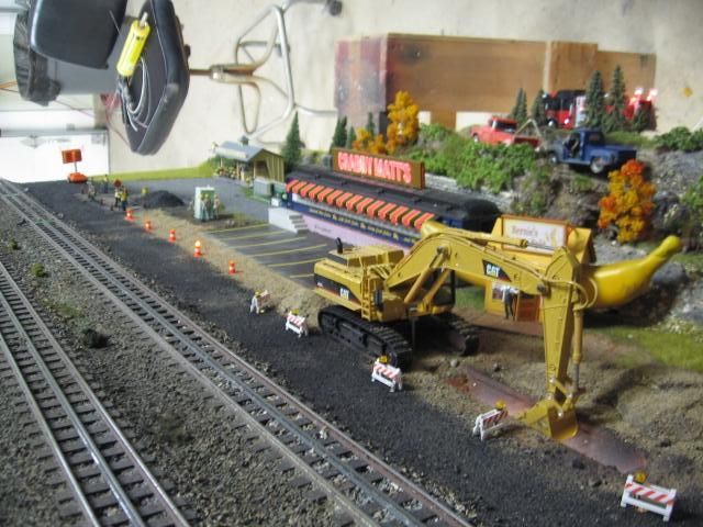
We are a non profit club open to the public 3 days a week in a mall in Myrtle Beach SC. We display G, O, HO, N, and Z gauges. Our primary groups are O, HO, and N. My group, the "O guys" often referred to by our other jealous members as "THE OLD GROUP", we are the only group in the club that allows the public to touch and run our equipment.
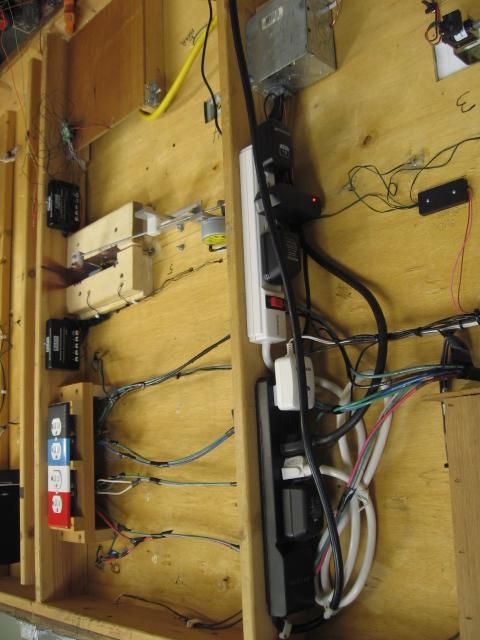
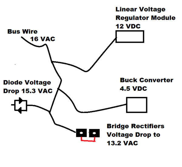
We just set up a new spur with a 16v ac bus line from a variable transformer. We would like to operate the following equipment off this spur and add more at a later date: 2 MTH lit buildings, a Lionel 6-2301 sawmill with log dump car, a Lionel 362 barrel loader and barrel car, and a Lionel 397 coal loader. We found that each accessory works best at a different voltage. Our problem is supplying a different voltage to each accessory while trying to use just one transformer.
I suggested using trim pots to regulate the voltage to each accessory. In my simplistic mind it seems doable. So now, I ask OGR members who know a lot more about such things, is it doable? If so what type trimpots would work best? Is there a better way to do this?
Thanks for any and all help.
Bob C.