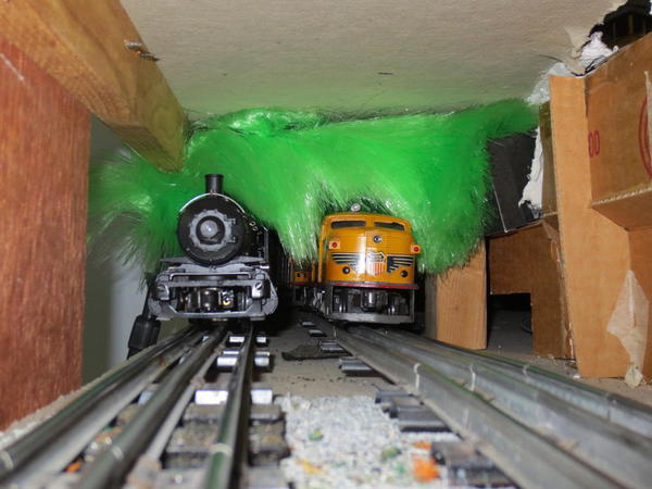
I didn't see any 'general' threads of simple fixes or unique ideas on how to fix equipment or any general procedures so I thought I'd start one.  I'm figuring most of these 'fixes' are quick and simple and can be done in a short period of time.   There can also be multiple solutions to problems.  All are good and, since we each have different skill sets, multiple solutions can better fit the modeler's comfort level to choose what is best for him/her.

This may go over like a lead balloon but we'll run her up the flag pole and see if anyone salutes!  

I'm hoping that if we put a 'post number' for each idea at the top of each post, we'll also to be able to easily find it (illusions of grandeur in case this thread becomes multiple pages) .

Original Post

Replies sorted oldest to newest

POST 2;

Loose pins on tubular track.

OK, I know I'm in the minority on my use of track but for us traditional (also cheap) track users, some needle nose pliers works great to close up those enlarged holes.

Also, a small hammer works great when the two tracks are pushed together and one rail sticks out farther than the rest.

Also, I find pins are easier to remove, if they are, first, lightly tapped into the rail before removing them with some pliers.

This also eliminated my engines slowing down on the far side of the loop.


track pins loose 01

Attachments

Images (1)
  • track pins loose 01
Last edited by samparfitt

POST 3:

making lanyards for your bell and whistle:

Lanyards added to bell and whistle.

An easy mod that was cheap and quick.

Stripped some 22 gauge wire and sprayed the strands black. Best to separate the strands before painting and leave hanging over a table top to dry individually.  Had to do 3-4 sprays by the time I finally covered all sides.

The holes in the bell and whistle arms had paint in them so they had to be re-drilled.

First I put the wires through the eye bolt on the side of sand dome and then ran it into the hole in the front of the cab, then the wire could be bent and placed into the hole on the bell arm.  Same with the whistle, only on the engineers side.

Bending the wire removed some of the paint but a black magic marker worked well on covering the brass wire.


GNM237

GNM238

GNM239

GNM240

GNM241

Attachments

Images (5)
  • GNM237
  • GNM238
  • GNM239
  • GNM240
  • GNM241

post 4:

Chuffing stopped/fixed:

I was enjoying some reading with the pleasant background of a GN M-2 chuffing along when all of a sudden there was silence   

I did all the usual stuff (even read through the manual!).

Logged onto OGR and advanced searched 'no chuff' under TMCC threads.

Tried all those suggestions, nada, but still knowledgeable and good info.

Reload, reset, move chuff switch, shake real hard (no, not that!), etc

Initially, I thought the chuff was electronically controlled.

I put her on her back and started rooting around:

Found a plate on the front set of drivers, removed it and voila, two cams (one for 2 chuffs and one for 4 chuffs).

Hooked up  the ZW and TMCC to the wheels and started her up.

Some contacts inside are moving against the cams, that's good: must be something else.

Remove two engines from boiler and the two green/blue wires going to the cam mechanism are no longer attached: MMM, looks like a possible problem !

The original wires were pretty short to I added about a 3" long extension to them.  Got some 22 gauge, multi strand wire, some heat shrink tubing and reconnected everything using electrical solder. 

Tried her again and "all's right in the world again'


The original wires have a stiff insulation on them and I think that caused them to break.  I used some very flexible wires (got them from my RC plane stuff).  I also had the engines removed from the boiler, previously, to check out the smoke system so that also may have weakened them.  Obviously, this break is most applicable to articulated engines since the front engine is always rotating on curves.

I did not worry about which way the wires were originally connected as I figured it's like a light bulb (either way works).


Also, it appears the cam system feeds the cruise control because the engine would slow down on the far side of the loop when not chuffing but works OK when the chuffing is operating.


Oh, and don't be an idiot, like me and use a red wire: best to use black,green,brown: something that is less visible.


One more item: there is a short piece of wire wrapped around the wires going to the cam and head light.  It is held in place, by friction, under the two valve mount brackets, so one bracket's screws need to be loosened to easily solder up all the wires.


GNM233

GNM234

GNM235

GNM236

Attachments

Images (4)
  • GNM233
  • GNM234
  • GNM235
  • GNM236
Originally Posted by samparfitt:

POST 2;

Loose pins on tubular track.

OK, I know I'm in the minority on my use of track but for us traditional (also cheap) track users, some needle nose pliers works great to close up those enlarged holes.

Also, a small hammer works great when the two tracks are pushed together and one rail sticks out farther than the rest.

Also, I find pins are easier to remove, if they are, first, lightly tapped into the rail before removing them with some pliers.

This also eliminated my engines slowing down on the far side of the loop.


track pins loose 01


I also use needlenose pliers to tighten the tabs that hold the rails to the ties.  This will also help with the loose pins and loose connections.  by quickly running through the ends of a box of used track using both methods, I was able to make a decent sized floor layout in my apartment without using track clips.

Originally Posted by Dennis:

Don't know what number to put on my post.  Looks like they are all you.

.....

Dennis

What about using a format like this:


Fixing a "Widget" -  Post 1


Then the next one on Widget fixing would be:


Fixing a "Widget" - Post 2


That way you easily find postings about a particular topic within the thread, and you could follow it sequentially, and it would allow for multiple postings from various contributors to the topic.


Just a suggestion


Greg


Last edited by Greg J. Turinetti

Greg,

You got it.

For post numbers, I figure we can just look at the last post number and add 1.

I'm sure some will get out of order due to multiple posts at the same time but it will still get referencing in 'the ball park', plus the last person's number that may be out of order, can just edit it for corrections.

Any additions or improvements to an original post, a Letter can be added:

ie  post 1-A

    post 1-B

    etc.

This way, all like posts can be easily referenced and the relationship.


Obviously, posts only refer to "how to's" and not general statements, like this post.

Last edited by samparfitt

Burfle,

You have a good point.

Like I said, this may not work, time will tell.

I'm figuring individual ideas will eventually be on page infinity and maybe difficult to find.

I'm also hoping those who may not post a completely separate post for a suggestion, thinking "it's too minor" that they would be encouraged to post it here.

As old as I am, there's lots of things that I don't know or didn't think of, and every person has something unique and interesting that they have thought of that would be nice to share with others. 

Also, a 'newby' to the hobby may not want to ask questions and this would provide answers that he didn't want to ask or didn't think of.


I'm hoping this will be kind of like a reference book, new posts will keep it current and on the first few pages.  One can then do a search on this post, and, hopefully, find what they want. 

Hey, like I said, this maybe a bad idea.  Try it and see what happens.

I'd rather try something and fail than sit and do nothing.


I'm not defending this thread or promoting it: it's just an idea that I posted and we'll see if users like it or throw it in the 'crapper'.

Last edited by samparfitt

POST 5:

switch mods:

1.  Sometimes there no room for the motorized portion of the switch.  It can be mounted under the table but I was too lazy.  Some wire and a few screws makes a crude, but effective, ground throw.  Some more scale like ground throws can be had from caboose hobbies.

2.  These are only toys, not antiques, so some cutting (used a band saw) of the turnout and rotating the cut off piece allowed the next spur track to be much closer to the straight track route.


switch mod 01

switch mod 02

Attachments

Images (2)
  • switch mod 01
  • switch mod 02
Originally Posted by Laidoffsick:

There's all kinds of HOW Tos around the forum, but they are in their own specific threads, usually in the specific forum that they pertain too.

Also, unless you post an index and have them sticky it to the top numbers are of little use. If you're looking for something specific like it has been said before, use the search feature.

If it ain't fixed, don't break it.


Jerry

POST 6:

JB weld versus soldering:


The front center return steam pipe on my articulated broke in half and, instead of soldering, I used JB quik weld.  These 2 part epoxy has metal impregnated into it and the 'quik' version dries in minutes versus the 'regular' jb weld that takes overnight to dry.


I had to removed the front engine from the boiler, first.  The return steam pipe (center of front engine) was broken.  The solder joint holding the two pieces of return steam pipe broke.  I used JB quik weld on these two parts.  Plenty of surface area as one piece of the pipe is solid and the other hollow so slopped the jb weld on both parts and let them dry. I used this method over soldering so I wouldn't have to re-paint the part.


NOTE: I had to do more PM on the front engine and the return steam pipe broke on me.  So to fix it right, I drilled a hole in the end of the front solid brass piece, used JB weld again, only put a piece of piano wire in the hole between the two pieces to give it a lot more strength than just the original surface area strength.

Lifting up the engine, that front set of drivers hanging there can put a lot of stress on this part.


NP Z-5 2-8-8-4 26

NP Z-5 2-8-8-4 26B

Attachments

Images (2)
  • NP Z-5 2-8-8-4 26
  • NP Z-5 2-8-8-4 26B
Last edited by samparfitt

POST 7:

Track power isolation (low tech but functional!).

For the yard, I wanted to be able to shut off each engine, if not in use.  Also good to turn off a post war engine while operating with DCS and/or TMCC.

Some wire, on/off switches and track lockons are all that's needed.


In this case the turnout got an insulating pin on both center rails.


track power isolation 01


Some wire (good ol' lamp wire from home depot) to connect the center (hot side) rail before the turnout to the center rails after the turnout via some on/off switches.


track power isolation 02


Connected the 'before' turnout center rail wire to, in this case, two on/off switches.

The wires on the output side of the on/off switches, then connect to each center rail on the track spurs.

A voltmeter on 'R' let me know which way was off on each switch.


track power isolation 03


Took about 15 minutes to isolate the spur tracks to shut down each engine's power.

To be even more cost effective, just solder the wires to the track!


track power isolation 04

track power isolation 05

Attachments

Images (5)
  • track power isolation 01
  • track power isolation 02
  • track power isolation 03
  • track power isolation 04
  • track power isolation 05
Last edited by samparfitt

POST 08:

Traction tire replacement (steam engines).


I couldn't find a 3mm socket to fit the hex head bolt so, initially, I tried some small needle nose pliers.  Worked on one side but I scratched the bolt head so I went to harbor freight and got a set of fine screw drivers for 5 bucks.


traction tire replacement 01


The power grinding wheel was needed to thin down the outer wall of the 3 mm screw driver so it would fit inside the side rod hole.


traction tire replacement 02


Depending on how scale your side rods are, only one hex head bolt needs to be removed for articulated side rods else all the bolts will have to be removed to move the solid, one piece, side rod over to allow the traction tire to be added.

If you have to remove all the bolts, note where the offset crank is located before removing it.  It's normally just facing off center, counter clockwise.  If you get it mounted way off center, you can have binding.


traction tire replacement 03


Pretty nice enhancement in that a small brass bushing is inserted between the stud on the driver and the hole in the side rod.  The bushing should get all the wear so the bushing can be replaced versus a worn out side rod.  The washer holds the side rod to the driver via the bolt. (don't even loose any of these parts!)


traction tire replacement 04


A dental pick makes quick work putting on a new traction tire.  The rubber tire is about a 1/4" less in diameter than the driver diameter.


traction tire replacement 05


Some thin CA, first put on a toothpick (keeps applying too much). and then touching the sides of the traction tire allows the CA to wick in and better secure the traction tire to the driver.  A small flat screw driver may be needed, later, should you have to remove the old tire, via a little scrapping.  For for when you have those, accidental, fast starts!


traction tire replacement 06

Attachments

Images (6)
  • traction tire replacement 01
  • traction tire replacement 02
  • traction tire replacement 03
  • traction tire replacement 04
  • traction tire replacement 05
  • traction tire replacement 06
Last edited by samparfitt

POST 9:

Chuffing stopped (TMCC)

Chuffing was intermittent on my 3rd rail NP Z-5 yellowstone.

As with my GN M-2, I figured a wire got shorted out or broke.


The chuffing cam is on the front set of drivers so I removed the base plate to check out the cam assembly.  The wires route through this area and over the gear box so I figured a wire is shorting somewhere in there.

I moved the wires forward to get some slack to the cam assembly.


NP Z-5 2-8-8-4 50

NP Z-5 2-8-8-4 51


Two screws hold the on/off cam switch in place, via a piece of brass, so the cam lobes can brush against the red button on the cam switch for the chuffing. 


NP Z-5 2-8-8-4 52


I put power to the engine on her back and still no chuffing so I manually pushed on the button and it worked.  Wasted a good hour finding out the wires were OK

There are two red pieces of fiber board to maintain the proper distance from the cam to the cam switch. 

I thought I could remove one and lower the switch but the clearance was too tight and the drivers stopped when the cam couldn't go past the switch.

I then put the cam back the distance it was and pushed on the piece of brass holding the switch to get the cam  a little closer to the cam.  That finally worked.


NP Z-5 2-8-8-4 53


Putting everything back together, one of the screws holding one of the valve gear came out.  Fortunately, I had some really small shoulder screws with thread just at the beginning of the screw. I think the screw came out while test running her on the track so that screw is long gone (another 15 minutes looking for it, an effort in futility!).


NP Z-5 2-8-8-4 54


NP Z-5 2-8-8-4 55


Put her on the track and the front drivers kept coming off on the curves.

Found out there's two holes to hold the front driver engine to the frame.  I used the back hole which didn't align the roller on the boiler to roll properly on the plate located on the front driver engine. On curves, the roller would fall off the plate.


NP Z-5 2-8-8-4 56


That shot a full day, but, at least, all is working again!

Attachments

Images (7)
  • NP Z-5 2-8-8-4 50
  • NP Z-5 2-8-8-4 51
  • NP Z-5 2-8-8-4 52
  • NP Z-5 2-8-8-4 53
  • NP Z-5 2-8-8-4 54
  • NP Z-5 2-8-8-4 55
  • NP Z-5 2-8-8-4 56
Last edited by samparfitt

POST 10:
Turnout problems.

Specifically, my new A-4 trailing truck was derailing while in reverse through an 072 switch.


turnout06


I made all my own HO switches so I applied this skill set to the 3 rail and  I noticed that most of the points of the 072 turnouts were very blunt so I filed the top edge to put about a 30 degree angle, wedge style at that location, plus filing the 90 degree corner to about a 30 degree angle.


turnout01

turnout02


I also noticed that not all switches are the same (not sure if my 072's are from a current year or spread over many years). 

Some have very nice fine points:


turnout03


While others are down right fat:


turnout04


Another item:

The points in the above picture are actually bent at several angles while the below picture has the point in a nice even curve.


turnout05


Bottom line:

Looks for points that are nice and thin and also a nice continuous curve. 

BUT, if they are dirt cheap, buy 'em and file the ends of the points.


Also, when building and laying my HO turnouts, it was always best to have them perfectly flat, and, like in yards, good to have a very gentle slop away from the switch to let gravity help the cars through all those turnouts.  Turnouts, especially multiple lines of them, are not conducive to reliable operation when they are on multiple angles.  Keep all grades changes before and after turnouts.


One final note: stay away from S curves with the turnouts (that's usually asking for trouble).

Attachments

Images (6)
  • turnout06
  • turnout01
  • turnout02
  • turnout03
  • turnout04
  • turnout05
Last edited by samparfitt
Originally Posted by Matt Makens:

Ive often wondered why there isnt a "Repairs" forum

Matt,

I've thought the same. Surely it would not be a difficult thing to do? I have often wondered why Jim Barrett does not have his own little corner on the forum. Is the OGR Office afraid of some kind of possible legal action from the Dr. Tinker crew? And again there are the rude and crude few on the forum that have little or no respect for anyone that threatens their corner of the sandbox.

Last edited by Prewar Pappy

A repairs forum might be a good idea. But it would only work if people used it before asking a question. Why don't people use the search function? The same questions, with the same answers do get asked time and time again. I don't think a repairs forum would change that.

There is no shortage of people ready, willing and able to provide assistance. It's nice to be able to give someone else some help. Most people like to share their knowledge. I think that's why many boards succeed.


POST 11:


TMCC bad reception (3 problems)


Talk about trying one's patience!


I've been having intermittent reception.

Some times it would work and anywhere on the loop of track, it may fail.


I separated the tender and found the screw holding the antenna wire to the top tender shell was very loose.  That was an easy fix, or so I thought.

(picture bad but there's a loose screw in there, somewhere!)


NP A-4 4-8-4 25


Put her back on the track and, still, intermittent reception....grrrrr.

OK, let's hold the whistle down and start jiggling things (engine that is!).

HMMMM: put side movement on tender and whistle stops.


Got the volt meter out and started checking resistance: 

Got it this time, the front 4 wheel trucks flanges are touching the tender.

A little electrical tape along each side of the tender will fix that.


NP A-4 4-8-4 26


That's got to fix it:

Wrong again!

The volt meter was saying one wheel is shorting out to the tender shell.

Bummer, figure bad insulation.  Take the wheel set off and it works perfectly good with the voltmeter: what the $%&*.

Put the wheel back into the truck and find the side of one wheel will short out when touching the truck frame.  Some insulation washers on the outer axle, FINALLY fixed it......hopefully, so far, so good

The chances of 3 related problems being bad are pretty slim....well used to be:[]


Now, to my next minor problem: marker and number boards aren't working.


NP A-4 4-8-4 27

NP A-4 4-8-4 28


POST 12:


Steam engine '5 finger' pickup.

What works well for me is to grab the piston jackets and the back of the cab.

There's usually a lot of fragile (must be Italian!) piping just under the walk way and using a one handed pickup along the center of the walk way usually doesn't turn out well for my engines!  It's more work since the tender has to be disconnected but, in the long run, my engines are happier.


engine pickup 01

engine pickup 02

Attachments

Images (2)
  • engine pickup 01
  • engine pickup 02
Last edited by samparfitt

East River Tubes

Imagine this sticking out of the fascia on your layout at a city.


The idea is to place one or more PVC plastic pipes of a diameter large enough to hold 10 inches of sectional track so you can statically display a subway car, or perhaps an observation car heading for Grand Central Terminal, or a trolley car running under the city.


Have the PVC tubing protrude an inch or two from the fascia. Paint the inside of the pipe grimy gray, and put two strips of 3mm LEDs along the pipe. Power the track so the car lights work.


For the really industrious, have the pipes protrude at an angle.


Attachments

Images (1)
  • East River Tubes
Last edited by Bobby Ogage

POST 13:


Cutting track.


A band saw makes quick work on cutting track. I use a regular wood blade and the table saw is a non-metal cutting band saw but this works for thin metal cutting, also good for aluminum and brass cutting.  The metal is harder on the teeth but, with 105" blade, it takes awhile to wear it down.

The blade doesn't snag the track as when I use a hacksaw.    A piece of two by four with 3 grooves cut in it with a table saw will also work to hold the track in place if using a hacksaw.

A dremel cut off disk also works but, usually, the disk leaves an angled cut other that 90 degrees.


trackcutting01

Attachments

Images (1)
  • trackcutting01

POST 15:

OPERATING TMCC ENGINES VIA MTH DCS REMOTE.

(Note: I don't claim to be an expert on this subject so please feel free to add corrections and/or other resolutions).

One can operate both TMCC and DCS using their respective remotes but I decided to have everything under the DCS remote.  I don't know about the new legacy TMCC but I've got the very first TMCC cab 1 and I find the controls on the DCS are more intuitive to use than the controls on the TMCC (your comfort maybe the opposite).

A nice option I like on the DCS remote is being able to startup and shutdown an engine on the track.  For some reason it bothers me having the circuit board 'on' when the engine is not in use for long periods of time. With the DCS remote this is easy to do.  Unless, I'm missing something, with TMCC, I have to key in TR 1 and rotate the throttle down to turn off all engines....and then start up again to get another engine started after just running a different engine.


My new DCS system just came in today.  The very old one's circuit board fried (no fuses on the original).  It was so old that it had a VCR tape for instructions!

I've got three engines that are TMCC and set them all up under TMCC using the last two digits of the engine number (required before setting up under DCS).


I've got 4 track loops (trk 1,2,3,4).


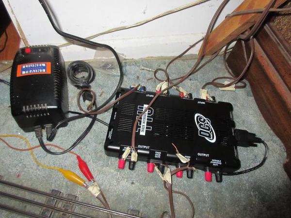
TIU

Input side:

Var in 2:

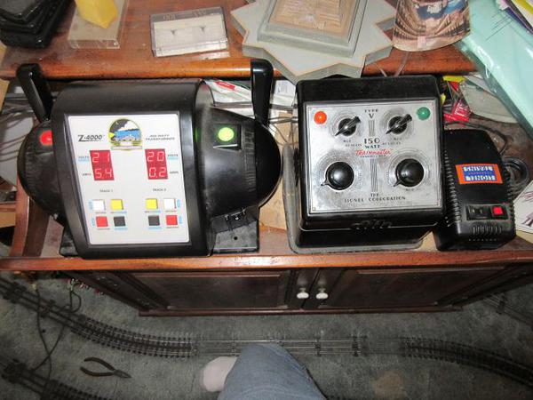
has a ZW-C with a brick.

Fixed in 1 and 2:

The MTH Z-4000 two outputs connect to these.

Var in 1:

a 180W brick.


Note: For power input, 4 bricks could be used instead of a ZW-C/L or z-4000. Best not to use old transformers as the circuit breakers are slow: not good unless you want to fry $200 engine boards!  At the slightest wheel off and short, the circuit breakers trip on my bricks: a hassle to go back to reset them BUT cheaper than new boards!  Best to keep the bricks within easy reach on a layout.


Output side:

Var out 1:

nothing connected

Fixed out 1:

Trk 1 & 3

Fixed out 2:

Trk 2

Var out 2:

trk 4.


NOTE: updated.

When running the 14 car passenger train, the passenger lights would oscillating dim and get bright and after awhile, the Z-4000 red light came on.

I'm guessing that due to the large number of passenger cars on all the tracks (32 cars), they were over drawing amps on the Z-4000 and causing the short (red) light to come on. 

Initially, I was not using var 1 output so I connected trk 1 to var 1 output to get more power (as Tim would say!).  Since Var 1 output is, like variable, I first have to select TR button and sel Var 1 and throttle up the volts to 18 (only gave it 18 versus the max of 22).  I also connected the TMCC base wire to all output grounds.  This seems to be working much better.


Output side now looks like:

Var out 1:

Trk 1

Fixed out 1:

Trk 3

Fixed out 2:

Trk 2

Var out 2:

trk 4.


Trk 1: runs TMCC engines (4)

Trk 2: runs just the SF PA set

Trk 3: runs MTH engines (5)

Trk 4: runs an old proto GN F-3 set (var 2 selection)


 Messy so see MTH's pictoral:

ps: the flat face V transformer runs a 5th track which is conventional.
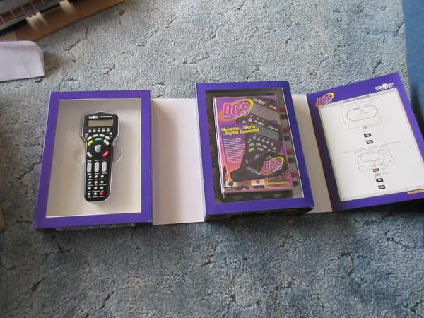
 

MTHDCSSYSTEM 01

MTHDCSSYSTEM 02

MTHDCSSYSTEM 03

MTHDCSSYSTEM 04


MTH DCS: hookup.

The pictorial (much neater!)

Need 50-1032 TIU/TMCC connector cable (each end is labeled)

Note: TMCC command base connected to output ground side.
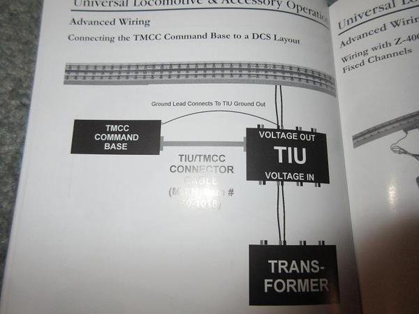
 

MTHDCSSYSTEM 16


Attachments

Images (5)
  • MTHDCSSYSTEM 01
  • MTHDCSSYSTEM 02
  • MTHDCSSYSTEM 03
  • MTHDCSSYSTEM 04
  • MTHDCSSYSTEM 16
Last edited by samparfitt

TMCC/DCS (cont)


Uploading TMCC engines into DCS remote.

Once all the wires are connected and all TMCC engines have been loaded in the TMCC remote, then (using the DCS remote) :


After pushing on menu button:


Select system:

(using throttle roller)


MTHDCSSYSTEM 05


select engine setup:


MTHDCSSYSTEM 06


Select add engine:


MTHDCSSYSTEM 07


select add tmcc engine:


MTHDCSSYSTEM 08


spell out name of your engine (throttle roller and press for each character)

ps: there is a blank for a space bar.

pps: when done, select D for done.


MTHDCSSYSTEM 09


scroll to your engines assigned number that was done in TMCC.

my case, last two digits of engine:


MTHDCSSYSTEM 10

MTHDCSSYSTEM 11


It'll now ask if you want to add another engine.

if no, press the ENG button.


MTHDCSSYSTEM 12


A summary screen comes out here but it goes to the main menu before I have time to take a picture of it.


scroll down to get inactive engines and press throttle roller to move new engine to active.


MTHDCSSYSTEM 13


can now select the TMCC engine and use the DCS remote on the TMCC engines just like the MTH engines:


MTHDCSSYSTEM 14

MTHDCSSYSTEM 15


Page 57-59 explains all this.

page 100 has TIU/TMCC interfaces.


Note:

This morning, I noticed power must be brought up with the TMCC command first (usual before ZW power) but also before DCS power is turned on.

Attachments

Images (11)
  • MTHDCSSYSTEM 05
  • MTHDCSSYSTEM 06
  • MTHDCSSYSTEM 07
  • MTHDCSSYSTEM 08
  • MTHDCSSYSTEM 09
  • MTHDCSSYSTEM 10
  • MTHDCSSYSTEM 11
  • MTHDCSSYSTEM 12
  • MTHDCSSYSTEM 13
  • MTHDCSSYSTEM 14
  • MTHDCSSYSTEM 15
Last edited by samparfitt

POST 15 (update)


NOTE: updated (also entered in original post).

When running the 14 passenger car train, the passenger lights would oscillating dim and get bright and after awhile, the Z-4000 red light came on.

I'm guessing that due to the large number of passenger cars on all the tracks (32 cars), they were over drawing amps on the Z-4000 and causing the short (red) light to come on. 

Initially, I was not using var 1 output so I connected trk 1 to var 1 output to get more power (as Tim would say!).  Since Var 1 output is, like variable, I first have to select TR button and sel Var 1 and throttle up the volts to 18 (only gave it 18 versus the max of 22).  I also connected the TMCC base wire to all output grounds.  This seems to be working much better.


Output side now looks like:

Var out 1:

Trk 1

Fixed out 1:

Trk 3

Fixed out 2:

Trk 2

Var out 2:

trk 4.


POST 16:

Replacing the smoke assembly in an MTH GN z-6 4-6-6-4.


Two screws under the cab and two through the center steam cylinders allowed the running assembly to be removed from the boiler shell. 

Unusual build as a lot of the large steam pipes are part of the drive assemblies instead of the boiler.


GN Z-6 4-6-6-4 08


In the center is a plate on the boiler and an L shaped stud on the drive engines that rides on this plate.  The L shaped hooks into the hole of the plate so the front engine has to be moved back a bit to release the L stud from the boiler plate.


GN Z-6 4-6-6-4 09

GN Z-6 4-6-6-4 10


The smoke assembly can now be easily accessed.

Two screws held it in place.

I ordered a new one (about $50) awhile ago.  The easiest test was just to connect up the new one with the two jacks (one for heating element and one for motor) and it worked.  The old one's motor is bad.

During reassembly, I made sure the smoke assembly aligned with the smoke stack hole.

 GN Z-6 4-6-6-4 11


Figured, I might as well grease the axles while she was on her back and oiled the other moving surfaces.


GN Z-6 4-6-6-4 12


Yep, I think it's fixed

OOP's: another tire off, back to the bench to fix that :[]


GN Z-6 4-6-6-4 13


Attachments

Images (5)
  • GN Z-6 4-6-6-4 08
  • GN Z-6 4-6-6-4 09
  • GN Z-6 4-6-6-4 10
  • GN Z-6 4-6-6-4 12
  • GN Z-6 4-6-6-4 13
Last edited by samparfitt

POST 17:

Tire  replacement (MTH E-8's)


In POST 1,  a K-line diesel tire replacement was easy (easily removed side frames).

These E-8's had to have:

4 screws to remove diesel shell.

motor removed (screw at bottom of frame)

2 screws to remove the front pilot

2 screws to remove ladders.

4 screws to remove both side frames.

This set is pretty old (proto 2) early era.

Hopefully, the newer diesels are more PM friendly.

Greased, oiled her while on her back.


ERIE E-8 A-B-A 02

Attachments

Images (1)
  • ERIE E-8 A-B-A 02
Last edited by samparfitt

As shown by Member samparfitt, in his photo, this is why I like MTH / DCS over the Lionel Cab #1 

     MTH, will run Lionel Engines, (TMCC) Lionel is not engineered to run MTH equipment, YES, there are some minor limitations, but all is well on my layout.

      Would not recommend this process for Lionel Legacy.

See his photo below.....     Click his photo to enlarge.

MTHDCSSYSTEM%2008

Attachments

Images (1)
  • MTHDCSSYSTEM%2008

I'm glad you like it, Roy.


========


POST 18:


Light replacement in a railking engine.

I can't say all rail king engines are like this but this N&W J removal of the running gear from the boiler shell is a whole lot easier than my previous dis-assembly of a scale articulated.  Only 4 screws (2 in front and 2 in back) and you're done.


railkingJN&W J 01


Nice touch by MTH: they lined the inside of the boiler shell with a clear plastic to make sure no electrical parts touch it and toast the circuit boards.


railkingJN&W J 02


Light (as well as smoke unit) is easily accessed.

While working on her, she got greased and oiled, and new traction tire added.


railkingJN&W J 03

Attachments

Images (3)
  • railkingJN&W J 01
  • railkingJN&W J 02
  • railkingJN&W J 03

POST 19:

Broken truck on railking N&W J.

Two metal tabs that are cast in with the side trucks frames broke off on the tender.

A few years ago, I noticed some of the white powdery material showing up on the coal pile that 'broke through' the paint.   I'm not a metallurgist but I think that white powder comes from contaminated cast metal.  I sprayed some wd-40 on it and that seemed to stop it as the white power never returned.  It was so small of an area that the paint was not marred (maybe not noticeable due to the rough coal look).

Anyway, this contamination may have been in the side truck frames since one was broke (or I could have been rough on it also, pretty old engine).  The other truck seems OK. 

Not willing to order a new part and wait, I used some quik JB weld to repair the damaged tabs.   Figuring, I wouldn't get the tabs exactly correct, I JB welded the side truck straight to the tabs as well as to the center steel truck frame, with the wheels in place. 

After fixing one side, the other side tabs came loose so, now, both sides are now JB welded. 

Some new side truck frames would be ideal but this 'fix' seems to be holding up well, so far.


railkingJN&W J 04

Attachments

Images (1)
  • railkingJN&W J 04

POST 20:

Light replacement in MTH N&W 70' Madison (heavy weight) passenger cars.

Base removal is easy on these cars.  Just 6 screws hold the metal base frame to the top plastic shell.

A nice touch by MTH using small copper tabs in the shell to make contact with the base, eliminated any wires between the two, which make it much easier to PM the cars.


premier N&W madison pass cars 01


These cars are pretty old and they have incandescent lights along the top of the car.

I'm guessing that newer cars are probably using LED's.

Again, I didn't want to wait to order new bulbs, so I used some Christmas replacement bulbs from a wal-box.  They are only 12 volts so time will tell if they hold up to the 18 volts.  Even though the bulbs are in parallel, I'm hoping running all the cars together, reduces voltage to each light and survives the 18 volts to the track.  These light bulbs have been used in some of my modern accessories where this type of bulb is used.  I find it easier to just replace the bulb versus trying to have a lot of different bases available for each type of accessory, and keeping the voltage at 12 or lower usually extends the bulb's life.


premier N&W madison pass cars 02


The new bulbs had shorter leads on them so I had to extend the leads but cutting off the old bulb's leads and sticking them into the holes and wrapping them along the sides of the base (not very professional but it seemed effective!).  Some new bulbs would be a lot easier but 'good enough' for now.  I also noticed that the new bulb's leads had a coating on them and some fine sandpaper was needed to make good electrical contact.


The grey interior seat/wall piece has a hole in one end which goes over those two copper tabs, allowing the lights to make contact with the metal base.


MTH has a nice web site for ordering parts via the online.  If you can't find the part, you can also call them and order direct.

Also, if you need a tech guy, it appears that Tuesday through Thursday from noon to 5 (EST) are their 'help the customer' hours.


Old burned out bulbs:


premier N&W madison pass cars 03


New bulbs:

premier N&W madison pass cars 04


New bulb in old socket:


premier N&W madison pass cars 05

Attachments

Images (5)
  • premier N&W madison pass cars 01
  • premier N&W madison pass cars 02
  • premier N&W madison pass cars 03
  • premier N&W madison pass cars 04
  • premier N&W madison pass cars 05
Last edited by samparfitt

POST 21:

MTH track voltage monitor (pretty cool option).

While 'playing' with the remote while the engine was running, I discovered I could find the track voltage at the location of where the engine is located on the track.


In my case, this track loop voltage is set by VAR 1 option (in this case I put it at 22 volts).  Initially, I was just using 18 volts so as to not overload TMCC engines but the max voltage at the wires via the engine only read 14.5 volts.


track voltage 01


I then selected ENG and scrolled back to the engine that I was running.

I hit soft key S5 (-- >  ) three times and then hit S4 (more) to get to the more options screen.


track voltage 02


I then scrolled down to 'track voltage' option.


track voltage 03


Each time I hit the speed roller, the voltage shows up for where the engine is at that time on the track.

Obviously, the highest voltage was where the wires connected to the track (only one set for the loop).  What was surprising was the voltage found was only a max of about 16.4 volts.  The far end of the loop got down to around 15.0 volts.

The amount of voltage screen shows for several seconds and then goes back to the 'track voltage' screen, so clicking again on the speed roller gives a new location track voltage.

This gives one a good way to analyze for low voltage spots on the railroad.

Pretty cool, and a lot easier than using a volt meter, especially if you have tunnels!


I've only tried this on a MTH engine.  I'll have to try it for a TMCC engine to see if it works, although I'm thinking it won't due to software needed to be in the engine's circuit board to 'talk' back to the DCS remote.

NOTE: Checked the TMCC engine and it doesn't have this option.


I did make the assumption that the reading is from the engine.  Those more knowledgeable, correct me if I'm wrong.


track voltage 04

Attachments

Images (4)
  • track voltage 01
  • track voltage 02
  • track voltage 03
  • track voltage 04
Last edited by samparfitt

post 22:

MTS DCS options:

Sounds:

On my DM&IR steam engine;

Pushing the Menu button and then Sounds,


coupler sounds (auto coupler) were activated.

pressing S2 to make auto so when the engine starts, coupler noises are made.


COUPLER SOUNDS 01


Brake sounds were also initiated:

Again selecting S2 for auto.


BRAKE SOUNDS 01


There is a 'clickity clack' sound that comes on after 30MPH but it turns off the chuff so I left this option off.


Marker lights are turned on/off with LIN (lights interior) at the bottom of the screen.

Headlight turned on/off with HDLT button at bottom of remote.


Again, this is for the DM&IR steam engine.

I'm assuming these same commands are valid for other MTH steam engines and, I'm sure, diesels have their own idiosyncrosies.

Attachments

Images (2)
  • COUPLER SOUNDS 01
  • BRAKE SOUNDS 01

Mark,

Always glad to help.

To be truthful, I'm also doing this thread for a selfish reason; it gives me a reference, in the future, when I have to do the same thing, I don't have to 're invent the wheel'.


============

POST 23:

Double decker full done cars, 70' by MTH.

I had the lights on two dome cars flickering so I figured a bad connection, somewhere (a light wack on the top would have them lighted for a short time).


Eight screws hold the base to the top plastic shell.

There's two sets of plastic interiors (top and bottom) that have to be removed. 


double decker dome cars 01


I found all kind of moth/insect parts inside: don't know how they managed that (plus he didn't even pay a fare!).


double decker dome cars 02


There are two sets of electrical contacts for the lower and upper lights.  They seemed a little squished so I used a small flat screw driver and elongated the spiral contacts (along with a little oil). 


double decker dome cars 03

double decker dome cars 04


Elongating the contacts seemed to fix her up.

It takes a little more finesse to put the bottom seat set and truck assembly back into the car shell with the upper seat set already in there as one set slides over the other set. 

All eight screws also need to be snug and everything fitting perfectly so those electrical contacts are flush to each other.


double decker dome cars 05

Attachments

Images (5)
  • double decker dome cars 01
  • double decker dome cars 02
  • double decker dome cars 03
  • double decker dome cars 04
  • double decker dome cars 05

POST 24:

More MTH DCS observations:

Some cool options under the softkeys at the bottom of the screen.


1. Measured route.

Can find out how long your loop of track is in scale miles.

Press speed roller once at a specific spot and hit the roller again after the train reaches that same spot after making the desired route.


measure route 01


2.  scale miles on your engine (Odometer)


odometer 02

odometer 01


3.  number of hours on your engine (chronometer):

In hours, minutes, seconds.


chronometer 01

chronometer 02


4.  commands for TMCC engines via the DCS remote:

    the bottom row on the screen has AX1 which is equivalent to AUX 1 on the TMCC remote.  Press on the button S1 just below  AX1 on the screen, then any number pushed on the keypay corresponds to a TMCC command, ie: AUX 1 and 9 gives smoke.


AUX ! under dcs


5.  appears that turning on the Interior lights on most of my DCS engines turns on either/or marker lights/number boards.


interior lights 01

Attachments

Images (7)
  • measure route 01
  • odometer 02
  • odometer 01
  • chronometer 01
  • chronometer 02
  • AUX ! under dcs
  • interior lights 01
Last edited by samparfitt

POST 25:

Fixing a paint chip.

My GN W-1 had a paint chip along the top center edge of the model.

I found some of my scalecoat great northern green was a very close match.

The paint is gloss versus the mat finish on the model so I put some minwax polycrylic satin over the paint after it dried.  I still need another coat of satin to remove some more of the gloss finish but you have to know where to look to see it.

I used a toothpick to apply the paint.  It best to just fill in the bare spot but I applied too much and it flowed past the chip.

There were a few other scratches on the horn and some piping but those were easy to paint without noticing that it's a touch up.

Places, like along the nose and flat areas viewed from the top are very difficult to fill in without noticing it.  Corners and lower sides are easier as light and the viewing angle makes it difficult to notice.


paint chip 01

paint chip 02

paint chip 03

Attachments

Images (3)
  • paint chip 01
  • paint chip 02
  • paint chip 03
Last edited by samparfitt

POST 27:

Uploading MTH manuals.

Figured I'd get all my manuals into my PC for future reference.

1) I don't have to dig the manual out of the original box

2) in case MTH drops the manual listing on their web site, I have it.  (didn't find a manual for my GN W-1)


MTH web site for manuals:

just type in the MTH model number and click on the 'open book' and then click on 'download' (upper right hand corner).  This asks for an open or save: I save it. It goes to my 'documents and setting'  but a search all documents will find it for you.  Then just copy and save to the desired file.


http://mthtrains.com/doc-search-results/20-2478-1

Last edited by samparfitt

POST 28:

CLOUDS for you layout (why didn't I think of that, 40 years ago!)


My Feb, 2015 NMRA shows how to add clouds to your layout.

Pretty cool.

Sorry, this isn't really a how to as the article is 10 pages long but the concept is simple and cost effective. 

The main parts are tulle (yeh, I've never heard of it either!), normally used for wedding veils at fabric shops and comes in different colors and poly fiber fill for the clouds.


ps: I wish the web's software wouldn't rotate the pictures 90 degrees!


clouds 01

Attachments

Images (1)
  • clouds 01
Last edited by samparfitt

Bobby, thanks for more posts.


=============

POST 30:

Added coupler slack noise but wasn't working.

With the other MTH engines, I only had to select the soft keys and select 'more' and then click S2 to move the 'coupler slack' noise.


With the GN R-2, I was getting no 'coupler slack' noise when starting the engine throttle.


MTHDCSSYSTEM 17


I also wasn't getting any smoke so I deleted the engine and re-added the engine.

That fixed the smoke but not the 'coupler slack'.

After 'playing around' with the remote for several minutes, I found that I had to increase 'engine sounds volume' under the menu key under sounds.

The volume was at zero.   A simple scroll of the throttle wheel increased the volume.


MTHDCSSYSTEM 18

Attachments

Images (2)
  • MTHDCSSYSTEM 17
  • MTHDCSSYSTEM 18

POST 31:

Resistance soldering.

A GN switcher's cow catcher's soldering joint broke free from the horizontal platform.

After cleaning off the paint in lacquer thinner, a little flux along the soldering joint, the two parts were clamped together with an alligator clip.

An anvil with an alligator clip help the parts, the resistance soldering ground was then clamped to the anvil.  With the solder held along the seam, it took about 2 seconds (if that) to melt the solder once the positive side tip was touched to the seam.

Any other method of soldering would probably have resulted in a lot of soldered parts falling off.


resistance soldering 01

resistance soldering 02

Attachments

Images (2)
  • resistance soldering 01
  • resistance soldering 02

mega steam smoke fluid.

Ordered the 8 oz bottle online after not finding it during the winter at any of the train shows.  Tried about 5 different brands and I find this best for the Lionel units that aren't as robust as MTH engines.  I think you could dump motor oil into the MTH unit and it would smoke!

$16 is a good price and will last a long time.

8 bucks extra for shipping (paper envelope had $2.76 for mailing to Cincinnati, Ohio).

Last edited by samparfitt

Old fashion sawdust grass:

In case anyone wants sawdust grass (etc) a fellow still sells it.  I only see him at the Dayton NMRA show and didn't find any web site for him.  I'm assuming you'll have to write him via snail mail for the product.  I got a few bags of it.

Of all the meets that I go to in the mid-west, this is the only person I know that sells this stuff.  The bags are very in-expensive.  Good for those who want to make vintage looking layouts.

This guy is pretty old so you better buy it now if "you're thinking about it" (I don't think he even buys green banana's!)

See pictures for his address.


sawdust scenery 01

sawdust scenery 02


During the summer, I work on my RC warbirds, so I'll be away for awhile.  Presently, I'm finishing up a 120" B-25 Mitchell.


I did just get a new engine that will have to be painted (grey boiler). a nice NP A-4 4-8-4.


northern pacific A-4 09


See ya' in the fall.

Attachments

Images (3)
  • sawdust scenery 01
  • sawdust scenery 02
  • northern pacific A-4 09
Last edited by samparfitt

" During the summer, I work on my RC warbirds, so I'll be away for awhile.  Presently, I'm finishing up a 120" B-25 Mitchell."


Cool, who's kit was it and what engines are you using?


I was heavily into R/C planes and turbines but not any more, my new addiction is O scale "stuff"


I still have a bunch of Gas and nitro engines...


Love the B-25. We had a full size one in our small airport in San Martin, California. we were supposed to restore it, but some how the plan went cold. Last time I saw the poor B-25, it had some covers on the cockpit and looking so lonesome....what a waste!!!


BTW: Beautiful brass engine, please show us how you paint it...Cheers!

Last edited by BigBoy4014

BigBoy4014,

The B-25 kit is Ziroli's and two DA-50's go on the business end.

Here's my build thread if you want to see pictures of it (since the web cops won't let any non RR  items be pictured).


http://www.rcuniverse.com/foru...-25-mitchell-19.html  


Here's video of my 110" F4U corsair:

https://www.youtube.com/watch?v=ERTe1bnuPck  


If you do a search for my name samparfitt,  under the warbirds category, you'll find my other build threads:

P-47 thunderbolt

SBD dauntless dive bomber

F9F panther

P-61 black widow

B-26 marauder

F4U corsair

Nieuport 28

F6F hellcat

P-51 mustang

P-38 lightning


======

Painting engines:

All the parts are dis-assembled and laid out in a tray to keep everything in proper order.  I like to put all parts back where they came from since these are handmade so a side rod on one side might be a little different than the other side, etc.  There can be up a hundred pieces laid out.

The headlight is drilled out.  A new drill bit is used as an old bit may grab the headlight and twist it off the boiler front.  I use some pliers to hold the head light. 

The boiler front usually is just force fit onto the front of the boiler.

Sound cams are usually added, a slot needs to be cut into the bottom brass plate holding the drivers to the frame.

Alcohol is good for cleaning them up removing the grease and oil without affecting the clear finish.  Tarnish is OK as the paint sticks to that.  No primer is used, likely to cover up detail.

I'm partial to scalecoat so I use an airbrush to paint them and then a toaster oven set at 200 degrees for two hours to cure the paint.  Always put a thermometer in the oven, don't need to melt that solder!  Only one coat is needed (assuming you did a good first spray!).

This engine will be a gray boiler so any parts (like domes, etc) usually have a screw holding them on so they can be removed.  This saves time having to tape them up.

I just use lots of small pieces of masking tape put on a mirror and cut with an xacto knife into some very small pieces (1/16" thin or so to mask domes, cab front, etc that don't come off. 

All piping is done with a fine paint brush.


Last edited by samparfitt

This is a fantastic idea. I know there are several approaches to organizing this type of thread but it is well worth the looking through everything to see what you might be able to use. I have thoroughly enjoyed the many folks on the forum who have helped me this past 3 yrs. I find the search function does not get me where I need to go very often. Maybe so coaching as to how the search engine is designed to look up items would help.

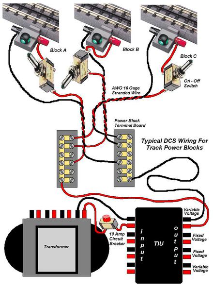
I believe that's called 'star' wiring because, theoretically, if you put the panel in the center of a circle of track and route wires to an even distribution around the circle, it will appear like a star.

Since MTH uses the rails to transmit the frequency, the star pattern gives the most uniform pattern to get the frequency to the motive power, versus just putting one set of wires on one side of the loop, resulting in the frequency to, possibly, weaken by the time it reaches the far side of the loop of a large layout.

Last edited by samparfitt

POST 32:

Make a functional back plate for a closed cab steam engine.


The back of that cab needs an enclosed back plate housing.


closed cab back plate 03


Some brass sheeting curved to match the width of the 'door' in the back of the cab.


closed cab back plate 02


Some flat brass sheeting soldered, (using resistance soldering) to the ends of the curved piece of brass sheeting.  The flat sheeting was larger than the curved piece to make alignment easier and then the waste was just cut away and filed smooth.


closed cab back plate 04

closed cab back plate 05


The back plate was made using some flat brass stock and soldering some L stock around the sides and then trimming to fit.  The inside hole made large enough to just fit over the cab 'door'.


closed cab back plate 06


Some U stock was drilled and soldered to the back plate.  Holes drilled in the U shaped pieces to hold the rods that will guide the back plate and go into the front of the tender.

Dry fit between tender and cab.


closed cab back plate 07


Fortunately, the supports for the rods are already on the tender but holes had to be drilled into the tender supports.


closed cab back plate 08

Attachments

Images (7)
  • closed cab back plate 03
  • closed cab back plate 02
  • closed cab back plate 04
  • closed cab back plate 05
  • closed cab back plate 06
  • closed cab back plate 07
  • closed cab back plate 08
Last edited by samparfitt
Love your videos nn Utube. I build a P 47 scale once. Loved RC flying but now spend all my time on trains. As a Naval Aviator though it is still in my blood. Originally Posted by samparfitt:

BigBoy4014,

The B-25 kit is Ziroli's and two DA-50's go on the business end.

Here's my build thread if you want to see pictures of it (since the web cops won't let any non RR  items be pictured).


http://www.rcuniverse.com/foru...-25-mitchell-19.html  


Here's video of my 110" F4U corsair:

https://www.youtube.com/watch?v=ERTe1bnuPck  


If you do a search for my name samparfitt,  under the warbirds category, you'll find my other build threads:

P-47 thunderbolt

SBD dauntless dive bomber

F9F panther

P-61 black widow

B-26 marauder

F4U corsair

Nieuport 28

F6F hellcat

P-51 mustang

P-38 lightning


======

Painting engines:

All the parts are dis-assembled and laid out in a tray to keep everything in proper order.  I like to put all parts back where they came from since these are handmade so a side rod on one side might be a little different than the other side, etc.  There can be up a hundred pieces laid out.

The headlight is drilled out.  A new drill bit is used as an old bit may grab the headlight and twist it off the boiler front.  I use some pliers to hold the head light. 

The boiler front usually is just force fit onto the front of the boiler.

Sound cams are usually added, a slot needs to be cut into the bottom brass plate holding the drivers to the frame.

Alcohol is good for cleaning them up removing the grease and oil without affecting the clear finish.  Tarnish is OK as the paint sticks to that.  No primer is used, likely to cover up detail.

I'm partial to scalecoat so I use an airbrush to paint them and then a toaster oven set at 200 degrees for two hours to cure the paint.  Always put a thermometer in the oven, don't need to melt that solder!  Only one coat is needed (assuming you did a good first spray!).

This engine will be a gray boiler so any parts (like domes, etc) usually have a screw holding them on so they can be removed.  This saves time having to tape them up.

I just use lots of small pieces of masking tape put on a mirror and cut with an xacto knife into some very small pieces (1/16" thin or so to mask domes, cab front, etc that don't come off. 

All piping is done with a fine paint brush.


Samparfitt, thx...Great WWII collection, all are my favorites, plus the FW-190D and the Zero....


That is a great F4U, the folding wings look fantastic and the engine (what is it?) and the four bladed prop sounded great. Is this the German Corsair Kit??


I flew Turbines powered F16, F18, F15 and so on...great EXPENSIVE hobby that was...Can't afford it anymore...

Great brass work too....How do you paint the drivers in black and keep the edges nice and shiny?


quizshow,

speaking of P-47:

110", scratch built, cut all my own wood.

takeoff:

https://www.youtube.com/watch?v=yATZhz6mAKc  


landing:

https://www.youtube.com/watch?v=YFoYkFPhYxQ


I was in the Corps, many moons ago.

====


Bigboy4014:

the engine is a Moki 250.  Has 5 radial cylinders and is a 4 stroke.  The prop is a 32", 3-blade, adjustable prop.

Yes, this is a Carf airplane.  The only one that is not built from a kit but still required a lot of hours to finish.

I'm mostly WW II prop but I have two jets: F9F with a jetcat P70 turbine and an F-86 that still needs an engine.

Like trains, these can get expensive. 

All mine are in the 8-10 foot wingspan and, except for the WW I nieuport, all have retractable landing gear.  Most have full cockpit detail, functional canopies, functional cowl flaps, navigation and landing lights.

I have a simple philosophy on spending:

If I bought a 40K car, nobody blinks an eye about that.

If I bought 40K worth of trains or planes, non hobbiest thinks that's crazy.

But, after 10 years, do I still have that vehicle and, if I do, what's it worth?

Yet, many years later, I still am enjoying my hobbies, and, they probably won't be worth what I paid for them, they are still worth more than that vehicle plus I can enjoy them for the rest of my life.  Besides, I worked 38 years (plus 3 years serving my country) and I deserve them

With the house and vehicle paid, my expenses are food, utility bills and house taxes: might as well use that 'old mortgage money' to buy something that I want!


Last edited by samparfitt

Quizshow904,

It is STAR wiring because it does not use any wire feeds that are common to more than one block. That is to say that every block has its own pair of (-) and (+) feed power feed wires. This style of wiring is advantageous for the DCS operating system because it minimizes digital signal distortion to Proto Sound locomotives.

DSCN1329

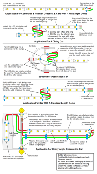
Conversion to LED lighting is underway in a Rail King 027 observation car. Note the lighting over the observation platform. The unconnected wires will feed 3mm LEDs to illuminate the marker lanterns.

DSCN1340

This observation has LED lighting. The drumhead is by Dan Maher. Why LEDs you ask? Relative to incandescent lighting,LEDs last thousands of hours, they draw much less current and LEDs are much less expensive than incandescent light bulbs.

Attachments

Images (2)
  • DSCN1329
  • DSCN1340
Last edited by Bobby Ogage
Originally Posted by Bobby Ogage:

Lets keep this great post going. Share your how-to-do-it ideas and projects! Post them here.

Bobby,

I agree.  Thanks for the tips on LED lighting!  I will certainly use them!  Though I was trained in electronics back in the mid '70s, it is just a job to me, and I like to leave it at work.  Therefore, I don't experiment with simple electronics to enhance my enjoyment of the hobby.  


I have something of value for O Gauge from my HO and N days that I need to write up and post.  I'll try to get that going sometime soon.


Thanks!!

Originally Posted by Bobby Ogage:

Quizshow904,

It is STAR wiring because it does not use any wire feeds that are common to more than one block. That is to say that every block has its own pair of (-) and (+) feed power feed wires. This style of wiring is advantageous for the DCS operating system because it minimizes digital signal distortion to Proto Sound locomotives.

Quizshow904,

To add to Bobby Ogage's correct comment; The star is common in electronics, and is the now preferred method for Ethernet wiring at businesses etc.  I like to think of the star as looking like an asterisk * sometimes called a star.  The central point where the wires tie together is the center of the asterisk, the middle of the star.  The far end of each wire is the point of the star/asterisk.  I hope this analogy helps.

That conversion to LED's will save a lot of wattage (and heat) being drained from the power source.


======

Post 32 (cont)

Back plate for closed cab.


Used a couple shoulder screws and some springs to support the curve, enclosed part to the tender.


northern pacific A-4 17

northern pacific A-4 18


northern pacific A-4 19


Holes in the tender for those rod supports had to be enlarged to allow lateral movement when the back plate rotates against the back of the cab.


northern pacific A-4 20


Some thin plastic sheeting CA'ed to the back plate to insulate the tender from the engine.


northern pacific A-4 21


Back plate plastic sheeting needs a little sanding and then, it just needs some painting, now!


NP A-4 4-8-4 25

northern pacific A-4 22


Attachments

Images (7)
  • northern pacific A-4 17
  • northern pacific A-4 18
  • northern pacific A-4 19
  • northern pacific A-4 20
  • northern pacific A-4 21
  • northern pacific A-4 22
  • NP A-4 4-8-4  25
Last edited by samparfitt

People Figures


I use 1/75 size people in the domes only. Everywhere else I use 1/50 people. You will need standing and sitting figures. It will also be necessary to chop down the legs of standing people a bit so you can see their heads when looking through the car windows. Be sure to put people walking in the aisles, and some standing people chatting with seated people. Like a guy trying to pickup a gal.


I use hot glue to secure the figures.


1-100 People in Coach [3)

El Platform [3)

DSCN1354

Attachments

Images (3)
  • 1-100 People in Coach (3)
  • El Platform (3)
  • DSCN1354
Originally Posted by samparfitt:


Bigboy4014:

the engine is a Moki 250.  Has 5 radial cylinders and is a 4 stroke.  The prop is a 32", 3-blade, adjustable prop.

Yes, this is a Carf airplane.  The only one that is not built from a kit but still required a lot of hours to finish.

I'm mostly WW II prop but I have two jets: F9F with a jetcat P70 turbine and an F-86 that still needs an engine.

Like trains, these can get expensive. 

All mine are in the 8-10 foot wingspan and, except for the WW I nieuport, all have retractable landing gear.  Most have full cockpit detail, functional canopies, functional cowl flaps, navigation and landing lights.

I have a simple philosophy on spending:

If I bought a 40K car, nobody blinks an eye about that.

If I bought 40K worth of trains or planes, non hobbiest thinks that's crazy.

But, after 10 years, do I still have that vehicle and, if I do, what's it worth?

Yet, many years later, I still am enjoying my hobbies, and, they probably won't be worth what I paid for them, they are still worth more than that vehicle plus I can enjoy them for the rest of my life.  Besides, I worked 38 years (plus 3 years serving my country) and I deserve them

With the house and vehicle paid, my expenses are food, utility bills and house taxes: might as well use that 'old mortgage money' to buy something that I want!


Good for you man! you have your priories straight.

LOL...I was selling Jetcats turbines about 10 years ago, still have dealer's jacket


sorry, I thought the F4U had a 4 balded prop, 3 blades just as nice, sounds great, I knew it was a radial from the sound of it..


I agree, model trains can get you some money back if you sell them in the future where as many others things and hobbies will not...


Thank you for serving our country.


The mother of my son is in a US air force base in Germany and when I visit I see many families without their dads and my heart goes out to all the service men and women...

How to Build An Inexpensive Crane

The crane is built from Lionel parts found under tables at swap meets.


  • Collect 2 Lionel track piers from a 110 or 111 trestle set;
  • Collect a Lionel Bucyrus crane car, i.e. a 2460, 6460, 6560, etc.
  • Remove the trucks from the crane car and toss them into your junk box or scrap yard.
  • Paint and or weather the crane car.
  • Paint and weather the trestle piers.
  • Space the piers a distance apart so that the center of each pier will align with the truck mounting holes in the crane car.
  • Drill one hole in each pier to accept a drywall screw.
  • Mount the crane car on the piers and you are done.


Scrap Yard Crane [1)

Scrap Yard [1)

Attachments

Images (2)
  • Scrap Yard Crane (1)
  • Scrap Yard (1)

Road trip:

My local Division 7 (Cincinnati, Ohio) of NMRA has a one day bus tour of local (within 150 miles, or so) railroad interests.

This year we saw two On3 layouts, a club (50'X150') and a very cool full size 'age of steam' roundhouse.


The 'age of steam' is not open to the public but they allowed the NMRA a tour.  A fully functional roundhouse with pit, about a dozen steam engines, about 20 diesels and all kinds of cars.  One person owns it and has a working crew doing repairs, etc.

The roundhouse is the only one built in the last 60 years.  With such tremendous weight, I beams had to be driven down to bed rock (60') to support the turntable and wooden beams to support the roundhouse.

Very cool.

Some very nice scenery on the On3 layouts.

The large club layout has an actual interlocking tower 'armstrong' controls that move the turnouts on the one section of the layout. 


nmradiv7tour01

nmradiv7tour02

nmradiv7tour03

nmradiv7tour04

nmradiv7tour05

nmradiv7tour06

nmradiv7tour07

nmradiv7tour08

nmradiv7tour09

Attachments

Images (9)
  • nmradiv7tour01
  • nmradiv7tour02
  • nmradiv7tour03
  • nmradiv7tour04
  • nmradiv7tour05
  • nmradiv7tour06
  • nmradiv7tour07
  • nmradiv7tour08
  • nmradiv7tour09
Last edited by samparfitt

POST # 33.


Painting engines.

My 3rd rail NP Z-5 2-8-8-4 came black and I want it to have a grey boiler.

Normally, I disassemble the entire engine to paint them but this one is already painted and it also has all the electronics in it: so best to paint the boiler without any dis- assembly.


First I used some slightly soapy water and a toothbrush to remove any dust and oil and then blew off the water via an air hose.


NP Z-5 2-8-8-4 57


Next the boiler is masked off.

Initially, 1/16"-3/32" wide masking tape is used to outline the domes, thin widths needed to navigate the compound curves without kinking the tape.


NP Z-5 2-8-8-4 58


Some larger widths of tape is then used to build up the around the domes.


NP Z-5 2-8-8-4 59


Masking tape, a straight edge to cut the tape, a piece of glass for cutting the tape on the surface, tweezers and scissors and a toothpick to apply the tape without fear of scratching the existing painted surface.


NP Z-5 2-8-8-4 60


After all non-painting surfaces are covered, she is ready for painting.  Masking paper is from home depot (paint section) as all parts not to be painted needs to be thoroughly covered as spray paint has a nasty habit of finding the smallest hole. 

Like all painting, painting is the easy part, the prep takes all the time.  It took me about 2 hours to mask off the boiler.


NP Z-5 2-8-8-4 61


The paint is applied, vertically from back to front and then front to back at about a 45 degree angle, each way to get into all corners.  Then the paint was applied horizontally, left to right, right to left for the final coats.

After cleaning up the air brush, the masking tape needs to be removed before the paint thoroughly dries.  The paint can often be ripped off surfaces when the tape is left on until the paint is thoroughly dried (especially if you're 'heavy handed' and put on a thick coat of paint).  Care has to be taken not to touch the newly painted surface but much better than leaving tape on the model until the paint dries.  The pipes, etc still have to be touched up by hand and brush after the grey dries.


NP Z-5 2-8-8-4 62

NP Z-5 2-8-8-4 63

NP Z-5 2-8-8-4 64

NP Z-5 2-8-8-4 65

NP Z-5 2-8-8-4 66


I've used a binks for the past 40 (or so) years but I went to harbor freight and picked up an inexpensive airbrush and it works great for painting engines.


NP Z-5 2-8-8-4 67


Water filters is best used as close to the paint gun as possible.


NP Z-5 2-8-8-4 68


You don't need a 60 gallon air compressor but a small one with an air tank is nice (an air tank keeps the motor from running constantly).


NP Z-5 2-8-8-4 69


I'm partial to scalecoat (enamel base) paints.  A well ventilated area is needed (same with all spray painting).  I normally bake the painted parts at 200 degrees for 2 hours.  This allows quick masking and painting other colors on the same day.  An accurate thermometer should be used to insure the temperature is 200 degrees as those toaster/oven dials are not always very accurate (don't want to be melting solder joints and making your model into a kit!).

The Z-5, being not disassembled, will have to air dry for 1-2 days or until the odor is no longer noticeable.  


NP Z-5 2-8-8-4 70


Two days later:

I used a 50/50 solution of high gloss and flat gloss of scalecoat paint to get a match to the factories paint finish.


NP Z-5 2-8-8-4 71

NP Z-5 2-8-8-4 72

Attachments

Images (16)
  • NP Z-5 2-8-8-4 57
  • NP Z-5 2-8-8-4 58
  • NP Z-5 2-8-8-4 59
  • NP Z-5 2-8-8-4 60
  • NP Z-5 2-8-8-4 61
  • NP Z-5 2-8-8-4 62
  • NP Z-5 2-8-8-4 63
  • NP Z-5 2-8-8-4 64
  • NP Z-5 2-8-8-4 65
  • NP Z-5 2-8-8-4 66
  • NP Z-5 2-8-8-4 67
  • NP Z-5 2-8-8-4 68
  • NP Z-5 2-8-8-4 69
  • NP Z-5 2-8-8-4 70
  • NP Z-5 2-8-8-4 71
  • NP Z-5 2-8-8-4 72
Last edited by samparfitt

Post # 34:


Purchased 1/16" thick lead sheeting to weight my engines.  Comes in 1' widths and I got 4': should be enough to last a lifetime (at least mine!).

Use a utility knife or tine snips. Best not to use power tools that creates dust and wash hands when done and keep from kids.

Got it from rotometals which, strangely, is located in California (where everything is banned...except raising taxes!).


http://www.rotometals.com/prod...T45cgCFQutaQodX8kNFA 


lead 1 16 inch thick 01

Attachments

Images (1)
  • lead 1 16 inch thick 01
samparfitt posted:

POST # 33.


Painting engines.

My 3rd rail NP Z-5 2-8-8-4 came black and I want it to have a grey boiler.

Normally, I disassemble the entire engine to paint them but this one is already painted and it also has all the electronics in it: so best to paint the boiler without any dis- assembly.


First I used some slightly soapy water and a toothbrush to remove any dust and oil and then blew off the water via an air hose.


NP Z-5 2-8-8-4 57


Next the boiler is masked off.

Initially, 1/16"-3/32" wide masking tape is used to outline the domes, thin widths needed to navigate the compound curves without kinking the tape.


NP Z-5 2-8-8-4 58


Some larger widths of tape is then used to build up the around the domes.


NP Z-5 2-8-8-4 59


Masking tape, a straight edge to cut the tape, a piece of glass for cutting the tape on the surface, tweezers and scissors and a toothpick to apply the tape without fear of scratching the existing painted surface.


NP Z-5 2-8-8-4 60


After all non-painting surfaces are covered, she is ready for painting.  Masking paper is from home depot (paint section) as all parts not to be painted needs to be thoroughly covered as spray paint has a nasty habit of finding the smallest hole. 

Like all painting, painting is the easy part, the prep takes all the time.  It took me about 2 hours to mask off the boiler.


NP Z-5 2-8-8-4 61


The paint is applied, vertically from back to front and then front to back at about a 45 degree angle, each way to get into all corners.  Then the paint was applied horizontally, left to right, right to left for the final coats.

After cleaning up the air brush, the masking tape needs to be removed before the paint thoroughly dries.  The paint can often be ripped off surfaces when the tape is left on until the paint is thoroughly dried (especially if you're 'heavy handed' and put on a thick coat of paint).  Care has to be taken not to touch the newly painted surface but much better than leaving tape on the model until the paint dries.  The pipes, etc still have to be touched up by hand and brush after the grey dries.


NP Z-5 2-8-8-4 62

NP Z-5 2-8-8-4 63

NP Z-5 2-8-8-4 64

NP Z-5 2-8-8-4 65

NP Z-5 2-8-8-4 66


I've used a binks for the past 40 (or so) years but I went to harbor freight and picked up an inexpensive airbrush and it works great for painting engines.


NP Z-5 2-8-8-4 67


Water filters is best used as close to the paint gun as possible.


NP Z-5 2-8-8-4 68


You don't need a 60 gallon air compressor but a small one with an air tank is nice (an air tank keeps the motor from running constantly).


NP Z-5 2-8-8-4 69


I'm partial to scalecoat (enamel base) paints.  A well ventilated area is needed (same with all spray painting).  I normally bake the painted parts at 200 degrees for 2 hours.  This allows quick masking and painting other colors on the same day.  An accurate thermometer should be used to insure the temperature is 200 degrees as those toaster/oven dials are not always very accurate (don't want to be melting solder joints and making your model into a kit!).

The Z-5, being not disassembled, will have to air dry for 1-2 days or until the odor is no longer noticeable.  


NP Z-5 2-8-8-4 70


Two days later:

I used a 50/50 solution of high gloss and flat gloss of scalecoat paint to get a match to the factories paint finish.


NP Z-5 2-8-8-4 71

NP Z-5 2-8-8-4 72

I have been a Scalecoat user since the 70s. I was a BN nut back then and used Scalecoat because the Floquil BN green color was off. Still use it.

Dick

Rescued Trains posted:

Wow, what a great thread full of useful information. How is it that there haven't been any new tips for over 2 and half years?

Just wondering,

Steve

I forgot about this thread.  I put a lot of my "how to's" on my GN thread; ie, tree making, installing miller signs, painting engines, etc.   The railroad is HO but a lot of stuff can be applied to any scale.  There's posts about other stuff, as well, so you'll have to page through it to find things.  The page listed below has the miller signs install and tree making.  Recently, the thread has installation of new scenery and about 450 additional trees installed.

https://ogrforum.ogaugerr.com/...thern-railway?page=6

Add Reply

Post

OGR Publishing, Inc., 1310 Eastside Centre Ct, Suite 6, Mountain Home, AR 72653
800-980-OGRR (6477)
www.ogaugerr.com

×
×
×
×
Link copied to your clipboard.
×
×