I have owned my Legacy base for nearly 4 years. I tried hooking it up when I first got it, and all my trains ran away, an indication that they were getting no command signal and waking up in conventional with 18 V on the rails.

I thought I would be brave (and smart) today and give it another shot. I still want and need my TMCC base for my Cab-1's. No biggie, use the "Y" cable.

Just to show everyone how I hooked it up, and that I have the correct ends in the right places, I took pictures. Then I shot a short video to show what happened.

Here's the Legacy base with the layout connected to the U terminal, and the correct cable end plugged in.

IMG_6242

Here's my trusty dusty TMCC base with the correct cable end, and no U terminal connection.

IMG_6244

Here's the unused serial end. Eventually that will go into my computer which will issue commands to the trains.

IMG_6239

Because there are a lot of engines on the track on the upper deck, I unplugged the power supplies that feed the upper deck. Trains on the lower deck are already on isolated tracks.

IMG_6245IMG_6247

I shot this short video of what happened when I turned the power on. At 8 seconds in I flip the layout power on. The TC&W engine starts grinding away, pushing on the BNSF. Lights come on, on a number of other engines. At 18 seconds, the power goes off to the rails, and all engines go quiet and dark. The way they were supposed to. Shortly after that you can see me turn off the master power switch.

Who remembers the movie Big? How did the Zoltar machine work when it was unplugged.

I'm open to suggestions here, or do I have to call Ripley?


Attachments

Images (5)
  • IMG_6242
  • IMG_6244
  • IMG_6239
  • IMG_6245
  • IMG_6247
Last edited by Big_Boy_4005
Original Post

Replies sorted oldest to newest

That's OK Scott, I went through that exercise 4 times prior to shooting that. At least it was still doing it with the camera on. It was nice to be able to time the duration of the event. Previously, I would just flip the switch, hear the trains moving, and quick flip it off. I didn't have trains as well isolated, so I never left them on long enough to really see what happened.

I still haven't figured out where the track power came from, and then 10 seconds later it goes dead, likre it was supposed to.

Rick, the TC&W is a converted Railking with an ERR board. Matt Makens did the install, and I'm pretty sure he lengthened the antenna when he did it, since he had been doing that to a bunch of other locos for me.

There was another engine that wanted to take off, a little further up that track off camera. That was a Lionmaster SD whatever. That was the engine that was used for the first run around the upper deck, and had signal problems in a few spots in that video. The rest were lights only, but where did any of them get their power?

I may still be on a really version of Legacy, I'll have to run down and look. Why does 1.4 sound familiar?

Last edited by Big_Boy_4005

Are you powering the legacy base and the layout at the same time?

Its recommended that the base be powered first so it can get the signal to the track so the engines don't drop into conventional. Given the massive size of your layout I'd probably power the base up and wait a few seconds to power the track.

Is there some a loco or something "bridging" power from another block? The base shouldn't have anything to do with power to the track.

I'm confused about the power question? If your putting power to the track  most TMCC/legacy locos will have lights that come on.

Only the most recent legacy offerings actually stay completely dark until addressed. 


Last edited by RickO

Since you are able to video and I might say very well, to help solve this problem, just video all your connections from the legacy base to track, transformer and what type of engines you operating (legacy, TMCC or conventional) and show all wiring you have to the wall switches etc. The more detail you can give the better the answers will be to help solve this problem.. 

RickO posted:

Are you powering the legacy base and the layout at the same time?

Its recommended that the base be powered first so it can get the signal to the track so the engines don't drop into conventional.

Is there some a loco or something "bridging" power from another block? The base shouldn't have anything to do with power to the track.


I've thought that powering the base first may be the answer. Right now bases and track power up on the same switch. That would mean trying to put the power supplies on a delay circuit.

I don't think there was any possibility of trains bridging power to that track. Those 3 supplies cover just the upper deck. I just rewired the lower deck supplies to minimize the number of transitions. Transitions occur at turnouts, a natural center rail break.

There shouldn't be any power there, that zone was unplugged.

Last edited by Big_Boy_4005
woody posted:

Since you are able to video and I might say very well, to help solve this problem, just video all your connections from the legacy base to track, transformer and what type of engines you operating (legacy, TMCC or conventional) and show all wiring you have to the wall switches etc. The more detail you can give the better the answers will be to help solve this problem.. 

Actually Woody, the stills above do show all the connections. I use the classic single wire from the base. When I just use my TMCC base, everything is fine. I hook up the Legacy, and nothing but trouble. That's why it's been on the shelf for the last 4 years.

There is no conventional possible on this layout. Binary control, on or off, no in between. There are about 30 engines on the rails, wide variety, all diesels except my Challenger. Mostly Lionel, some Atlas, and a few conversions.

Gregg posted:

I'm  guessing you tried a different wall outlet for the Legacy base power adaptor? 

Actually, I haven't. But I know the outlet is good, because I wired the entire house. Beside, the TMCC base has been working off the same outlet for years.

At this point Rick's suggestion of the time delay between signal power up and track power up seems most plausible. I think I'll pull the other 3 plugs from the second set of supplies. Then everything better stay dark. Then I can selectively power up, and see if I only get lights, no sound, no movement.

RickO posted:
MartyE posted:

What is the power source?

One thing I find odd.  A Legacy or TMCC engine when first powered, if it wakes up in conventional, should just start up in neutral.  I'm not sure why one would be trying to move forward unless power is cycled.

If theres no track signal they take off when powered up at 18v

It seems I am incorrect.  I guess that is only for the first time on a conventional layout.  It was my understanding they came up in neutral.  My apologies.

Last edited by MartyE

There appears to be a lot of possible variables here.  If I am following everything properly, the Legacy System has never worked properly for you.    If this is the case, I would set up a test circle/track with its own power supply and test the legacy system there.   If there is still an issue, I would test another train just to confirm and a different power source.   If there is still an issue, then it would appear to be a problem with Legacy unit.

But if the test circle unit works, I would retest using the primary power outlet used for your layout.

If still good, I would attempt to get a power feed from your primary transformer.

If still good, I would attempt to hook up the 'Y-Cable' only.

If still good, I would attempt to hook up the TMCC Base

With this approach, it will help you identify what works and what cause the system to fail.

Hopefully it turns out to be something simple like a bad connection or "Y-Cable", instead of something with your layout since it looks like you have a complex layout.  But since it worked with your TMCC base, this seams odd.

Two additional test:

If you just hook up the Legacy Base - Leaving the "Y-Cable" and TMCC base disconnected, does that make any difference.

Also you may want to try hooking the TMCC-Base up only - to see if your original configuration still works.

Just my two cents.

OK guys, here's what I found out when I ran downstairs for more testing.

I found two manuals in the file, one for 1.3 the other 1.4. I want to say it came with 1.4, but when I registered it, Lionel sent me the 1.3. If I remember correctly, 1.4 had just come out, and this one had it. So, that's that.

Now for the power situation. I have 6 power supplies located on 2 panels. One on the north side of the room and one on the south side, each with 3, 20A transformers. Actually, they are made up of 3, 6.3V transformers connected in series. This the south panel. The north one is exactly the same.

IMG_6236

There are 2, 12 gauge ground wires connecting the panels directly. The command bases are located in the center of the room, away from the power panels. The bases and the power supplies are controlled by a single switch near the entrance to the layout, which you saw in the video.

I unplugged all six supplies, then flipped the power switch. The command bases came on, and I waited about a minute, then I plugged in the first supply on the south side. Trains on that part of the layout were sitting on isolation tracks, and all was quiet. The second supply covered a part of the layout with no trains, still good. The third one, which is contiguous with power districts from the north panel, fired up a bunch of trains, and this after at least 3 minutes of Legacy base power up. I repeated this process on the north panel, trains were flying everywhere. I started to remove the offending engines. I couldn't get to the 10 second threshold without having a disaster. I finally gave up.

Bottom line, it doesn't seem to matter how long the base is powered prior to applying track power. I also know that I have a previously undiscovered and unwanted electrical connection that will have to be found.

Attachments

Images (1)
  • IMG_6236
Dale Manquen posted:

All those yellow things don't happen to be Polyfuses that could cause a delayed shutoff as they heat up, are they?

Excellent eye Dale, they are, and that would explain the shutdown after 10 seconds. They are a 6A version, so a few engines running at the same time in one power district would trip them. That's one part of the mystery solved. Thanks, totally slipped my mind. Fresh eyes on the problem really help.

Are you still doing house calls? I'm beginning to lean toward the idea that there may be too much layout for the signal that the base is putting out. Matt Makens took the base home to test it and said it was fine, ran his trains perfectly. I'm dealing with over 3000' of track, and it may just be too much.

BradK posted:

There appears to be a lot of possible variables here.  If I am following everything properly, the Legacy System has never worked properly for you.    If this is the case, I would set up a test circle/track with its own power supply and test the legacy system there.   If there is still an issue, I would test another train just to confirm and a different power source.   If there is still an issue, then it would appear to be a problem with Legacy unit.

But if the test circle unit works, I would retest using the primary power outlet used for your layout.

If still good, I would attempt to get a power feed from your primary transformer.

If still good, I would attempt to hook up the 'Y-Cable' only.

If still good, I would attempt to hook up the TMCC Base

With this approach, it will help you identify what works and what cause the system to fail.

Hopefully it turns out to be something simple like a bad connection or "Y-Cable", instead of something with your layout since it looks like you have a complex layout.  But since it worked with your TMCC base, this seams odd.

Two additional test:

If you just hook up the Legacy Base - Leaving the "Y-Cable" and TMCC base disconnected, does that make any difference.

Also you may want to try hooking the TMCC-Base up only - to see if your original configuration still works.

Just my two cents.

Sorry Brad, somehow I missed your post in the flood of replies. I like your scientific approach here.

Let's consider the test circle passed. As I just mentioned in my reply to Dale, Matt did that test and said it was good. TrainroomGary suggested that I send it to Lionel for repair, but I'm skeptical about that, as I suspect that they too would say it's fine. This has happened with a number of my engines as well, simple track test out fine, my layout crap.

I have never tried Legacy base only. That's an easy one, yank the cable and power up. Going back to TMCC has always worked, that's easy too.

Moonman posted:

Well, I briefly saw the cab light blink in the BNSF. Shaky signal. Disconnect the track wire and try a jumper from the track post directly to an outside rail.

it is better to power up the base first. It should go through some startup blinks, then a green light and blue Legacy lit.

Yeah Carl, I saw that too. I think it was just a result of the TC&W pushing on it. More of an incidental glitch than indicative of a new issue. We both know that I have signal issues under just TMCC on a good day. BTW, I did do a test run this afternoon prior to my Legacy foray, and I have the lower level signal problems pinned down to some specific spots. A glimmer of hope.

It took me a few rereads to get what you had in mind with the ground wire, but I get it now. Interesting, and another easy experiment.


Elliot,

  I find this a very interesting topic........ hope the remedy is located in a short period.  You stated the third power supply on the South panel is contiguous with districts from the North panel, correct?  Just a thought, but with this arrangement between panels, what about any back feed of power between the power supplies of South/North panels and related trackage ?  How much assist would it be should you meter the power feeds from the various power supply circuits and check for spikes, occilations, etc. ?

Just thinking...... sometimes a dangerous thing...!!

Jesse 

Yes Jesse, that's what I'm going to have to hunt down. It shouldn't be too difficult though, because the north and south panels only meet in a couple small spots. I just need to see if the feeders are on the right districts and are not somehow overlapping. Fortunately, I just reorganized the south panel and the north one was done some months back, so now they match my master list. Before I try to delve into diagnostics, a visual inspection may reveal the problem.

The only tool I have is a meter, no scope. Actually, a car with a light may be all the tool I need to find this. Just by plugging in one supply at a time, if there is an overlap, that should expose the location. Very low tech.

I love a good techno-mystery. Just not on my layout. In fact I know that my own layout has "leakage" in places between blocks but fortunately not enough to cause a problem. If it did I would be in a lot of trouble because I neglected to document my layout wiring with a useful schematic. While I know that there are useful on-line tools available for modeling a train layout as a circuit, I would be willing to pay for one that is model train specific. Especially if it had a feature that could estimate signal integrity for DCS and TMCC/Legacy.

It may have something to do with the fact that Legacy requires signal on both outside rails and you have all of yoru outside rails isolated to run the detection circuit and no signal is being transmitted to one rail effectively cutting your signal in half. I used that exact legacy base to successfully run trains on my 16 X 58 layout for a weekend with no issues. try connecting your detection rails to the legacy base and see if it works

That's an interesting theory Matt. I don't know if you ever noticed, but on the entire lower level, I have installed .1u capacitors at all the gaps. Those are specifically to allow the signal through, without actually "polluting" the rail with ground, so it can still be used for detection.

IMG_6237

Of course, it was the upper deck where all the chaos occurred. I never installed the caps, because things were running very well under TMCC. That's a big project to go back and solder up all those caps. I'm hoping the solution lies elsewhere.

Attachments

Images (1)
  • IMG_6237

OK So I'm not totally crazy.  I checked with Rudy who contacted Jon...

He stated that yes the R2LC, R4LC boards do start in FWD after a long power interruption after the initial neutral start up in conventional but the RCMC board will start in neutral after a prolonged power interruption all the time.  This changed was made because of the feedback from this forum.  I have yet to find a manaul though that states this.

I only have one outside rail connected to my Legacy 990 system and it works just fine here. I was going to use the other rail for controls and signals as you are doing. Of course your layout and Matt's layout are much, much larger. Mine is only 6'x16' with 2 loops of Atlas track and some spurs & sidings. It was wired for DCS, Legacy was added later by connecting just the one wire to my TIU output commons. Probably not much help here, but just thought I would mention it. Wish I had more to offer in the way of better help.

Elliot,

   Hay buddy are you running DCS also or just TMCC/Legacy?  If you are running DCS also simply connect the Legacy drop to the out Black Channels on the TIU and make sure you use the opposite outside rail for, your main Legacy drop.  My Multi level layout runs perfectly using Marty F's technique for Legacy/DCS, I know your layout is a lot bigger, but it's worth a try.

PCRR/Dave 

Last edited by Pine Creek Railroad

Sorry Dave, no DCS. 100% TMCC.

OK guys, I've done a few of the tests you suggested.

The Rick test: power base, then wait to power track     fail

The Brad test: straight Legacy, no "Y" cable       fail

The Carl test: straight Legacy, "U" post direct to rail      fail

The Carl test, Matt variation: "U" post direct to rail with both outside rails tied together     fail

The more I try things, the more I'm leaning toward Dale's diagnosis of a weak output on the base. Although, some of these tests were done with the engine in close proximity to the Legacy signal source. Is it possible that I have something near the base interfering with the signal?

That's an interesting point Rick. When I was just running TMCC, everything seemed fine, and all six supplies were plugged in. This Legacy testing exposed the wiring problem when I tried to selectively disable sections of the layout. At least two supplies are bridged, one north and one south. I'll do my "witch hunt" later. I'll look over my master list and try to narrow down the search. I don't think it will be too hard to find.

Yes Matt, but there may be a complexity factor or something environmental that you can't replicate on your layout. As I said before, I have engines that work fine when tested elsewhere, that don't work on my layout. You should know that better than anyone.

The fact that you had it working, leads me to believe that it could be where I have it mounted. Something is killing the signal.

Dale Manquen posted:

full 1 volt sine wave  ???

I see 6.3V peak-to-peak for my Legacy Base with no load on the Track output.

Yes, my base(s) have about 6 volts pp as well. Is it possible that on some layouts, at reduced output will function flawlessly and not work well on perhaps more extensive layouts. Or not on layouts with quite different environments? I have seen bases with low output around just less than 1 volt pp that were probablimatic and needed to be sent in for repair.

Disclaimer: Not an EE, in no way am I nearly as qualified as the folks who have already responded.

My $0.02 is: My dad (Nuclear Physicist) always told me that whenever something is "screwy" with your electrical circuit (trailer lights for the boat, Legacy signals ?), look for some kind of ground/common fault. I have always found this to be true.

So I mean no disrespect when I ask: Is "common" common throughout (For instance, is the TMCC "common" the same as the Legacy "common" for power, etc.)? I have had a lot of wiring issues with common (much smaller layout [who's isn't!] but three loop layout) and still had switches work, etc. It just seemed that there was always "a place that things didn't work well" which, ultimately, I traced to not have common wires "common" (i.e. "ground").

Just trying to help...

Bruce

Thank you Bruce.

Regarding the "common" none taken. The connection wire that I used is the same one that has been on my TMCC base for years. I just moved it over to the Legacy base, per Lionel's instructions. It goes out to the network of ground buses and track feeders.

If there's one thing I do have, it's feeders! Every 3' section of GarGraves track has a ground, a hot, and on the mainline only a detection wire. Non-mainline track has both outside rails tied to ground (no detection). The hots and grounds are tied to 12 gauge buses, and go back to the two power panels. There are two 12 gauge ground wires that just tie the two panels together and keep all six supplies on exactly the same ground.

I don't know if it is possible to have too many feeders. If it is, I might.

If TMCC base works fine. And the Legacy base appears to work fine on another layout. Bruce's comment on a ground fault is worth looking at.

Try using your Legacy set plugged into your normal layout power point. Then just try a short length of track seperate from the layout with a power supply  and one engine and see if it works correctly. If not try on another power outlet.

I recently had a issue with LCS which appears to have been due to a fault within my Legacy base. This sort of thing can be tricky to diagnose. I also had a ground fault from a Hellgate Bridge.

Maybe Lionel need to look adding a diagnostic aspect to the LSU software. So you could plug in a serial/USB cable into your PC and the software would test all the outputs were correct and everything is operating correctly. 

Nick


Elliot,

Referring to the comments concerning grounding, and having/not having, too many feeders.  I worked in club/large concert PA and Sound productions for years in the 70s.  One problem we came across at times was a "ground loop".  With this, as it sounds, a completed loop of grounding, there is a tendency for picking up of RFI.. Radio Frequency Interference.  In the business of sound reinforcement it caused severe feedback and the introduction of stray radio signals from Citizens bands, short wave, intercom systems, etc. over the stages PA systems.  Perhaps such a type of ground loop is produced within your layout wiring, and it is interfering with the signals to/from the Legacy base.

Any thoughts or comments?

Jesse

MOKATX and Harty Beatris RR


texastrain posted:

Elliot,

Referring to the comments concerning grounding, and having/not having, too many feeders.  I worked in club/large concert PA and Sound productions for years in the 70s.  One problem we came across at times was a "ground loop".  With this, as it sounds, a completed loop of grounding, there is a tendency for picking up of RFI.. Radio Frequency Interference.  In the business of sound reinforcement it caused severe feedback and the introduction of stray radio signals from Citizens bands, short wave, intercom systems, etc. over the stages PA systems.  Perhaps such a type of ground loop is produced within your layout wiring, and it is interfering with the signals to/from the Legacy base.

Any thoughts or comments?

Jesse

MOKATX and Harty Beatris RR


A few years ago, there was some talk about wifi interfering with the Legacy base signal and changing channel #'s might help.

OK .the Legacy works  at a friends layout.   You guys in the same town or hydro area?

 If both the legacy base & TMCC base are joined by a Y connection only one "U" connection    to the track    cab be used.          

In the pics   it looks like the " U on the legacy base is connected,,, Why not trying disconnecting it and try the command base  U connection.   fail?

Gregg posted:

OK .the Legacy works  at a friends layout.   You guys in the same town or hydro area?

 If both the legacy base & TMCC base are joined by a Y connection only one "U" connection    to the track    cab be used.          

In the pics   it looks like the " U on the legacy base is connected,,, Why not trying disconnecting it and try the command base  U connection.   fail?

Doesn't work that way. You need to use the Legacy base as the track signal. Legacy base does not communicate with the Cab 1 base. The Cab 1 base sends commands to the Legacy base. 

I HAVE FOUND THE ELECTRICAL BRIDGE. After mulling over my power district list, I concluded there was only one place to look. Districts for the north and south supplies touch there. There's a switch at the top of the big helix. This one happened to be a Ross Ready with all the center rail segments bridged together. Usually I cut those off for mainline switches, but obviously I missed this one. I'll get the Dremel and cut the two pins on the frog end, because I can't get under it to clip the bridge. That will separate the three districts and the two supplies. MYSTERY SOLVED!

There could be a lot of ground feedback loops, especially on the main level, where I'm having TMCC problems. When I wired the upper level, I just ran a single ground wire all the way around. I have good signal up there. My only concern is potentially over loading the 12 gauge wire by having it serve too many districts.

ampacity chart that I use rates 12awg stranded at 9.3 amps per 1000 feet for power transmission

This statement is incomplete.  You must tell us the nominal voltage and the percent of allowable drop.  Wire size vs. voltage drop tables are typically for 2% drop of some nominal voltage, and they are usually for a complete out-and-back pair of conductors.  For your example, for a 1000 foot loop your voltage would need to be 1500V to have a 2% drop.

Maybe the easiest way to deal with this whole ground business is to use one 12 gauge wire for all the districts on one supply. This will divide the layout into six reasonable zones. Since each supply can only deliver 20 A anyway, the wire would be appropriately sized. If you break it down in terms of trains, at 2 A load per engine (I use almost all can motors) that works out to up to ten engines per supply. I don't use multiple engines on a train, so we could be talking up to 60 trains layout wide. Trust me, that will never happen! Maybe 20 at the absolute max moving at any one time.

I'm afraid I don't have anything to offer that has not already been suggested by others at this point.

You have a fantastic layout, Elliot, and I do hope you can get the legacy base sorted out.  Others that have already chimed in would know a lot better than I, but my only thought is that there is some sort of load on the legacy signal grounding it out somewhere.  For those that know more than I do, does the Legacy base and TMCC base use the same output circuit, or is it possible that the TMCC signal is more powerful and can overcome a medium resistance connection to earth ground?

By the way, I love the idea of using the 6v transformers in series.  

JGL

Last edited by JohnGaltLine
Dale Manquen posted:

ampacity chart that I use rates 12awg stranded at 9.3 amps per 1000 feet for power transmission

This statement is incomplete.  You must tell us the nominal voltage and the percent of allowable drop.  Wire size vs. voltage drop tables are typically for 2% drop of some nominal voltage, and they are usually for a complete out-and-back pair of conductors.  For your example, for a 1000 foot loop your voltage would need to be 1500V to have a 2% drop.

Dale, I realize that now. I grabbed the chart from a manufacturer's site some time ago. I assume that this is referencing the load carrying ability before wire or insulation failure. I was originally concerned with trying to find some safety points of reference.

It seems to me that the distances needed to have a noticeable voltage drop for 12 AWG aren't found on most home layouts. It could be possible on Elliot's layout, but he has created multiple power divisions. I would not expect a voltage drop on his layout.

I was responding to his recent comment of concern  if the 12 AWG would be large enough.

I just tested my Legacy command base, curiously the voltage output was actually greater connected to the tracks than open circuit.  5.64VPP open circuit and 6.20VPP connected to the track.  There is only about 100 feet of track connected, not quite like the layout in question, but that seems to suggest what you should see as an output signal.  The ground for the 'scope was connected to the same power strip ground connection as the command base power brick.

Command base not connected to track, 5.64 VPP

ADS00001

Command base connected to track, 6.22 VPP

ADS00002


Attachments

Images (2)
  • ADS00001
  • ADS00002
Last edited by gunrunnerjohn

The TMCC Base had just a series coupling capacitor feeding the output, but the Legacy Base has additional inductor and capacitor components at that point.  I don't know if they are to help things going out or to filter things from coming back in.  Might be cutting down the digital trash from the internal clocked circuits, or not.  Anyway, they do seem to interact with the load's reactance.

Gregg posted:

 How    are things now?  Does legacy work anywhere? or same old ?


My helper Joe was over yesterday, so we worked on other things. Nothing has changed, except I located the electrical bridge as I mentioned in a previous post.

When I go downstairs later, I think I'm going to back to straight TMCC, while I try to simplify my ground wiring.

I ordered Dale's signal strength meter, which should be here Monday.  At this point, I would love to perfect the TMCC signal, then I can revisit the Legacy base after that. I'm afraid that thing is going back on the shelf for a while.

That said, please feel free to continue this discussion, I'll be listening, and others may find useful ideas here.

THANKS GUYS!!! THIS IS WHAT MAKES THIS FORUM SO GREAT.

Last edited by Big_Boy_4005
Big_Boy_4005 posted:
Gregg posted:

 How    are things now?  Does legacy work anywhere? or same old ?


My helper Joe was over yesterday, so we worked on other things. Nothing has changed, except I located the electrical bridge as I mentioned in a previous post.

When I go downstairs later, I think I'm going to back to straight TMCC, while I try to simplify my ground wiring.

I ordered Dale's signal strength meter, which should be here Monday.  At this point, I would love to perfect the TMCC signal, then I can revisit the Legacy base after that. I'm afraid that thing is going back on the shelf for a while.

That said, please feel free to continue this discussion, I'll be listening, and others may find useful ideas here.

THANKS GUYS!!! THIS IS WHAT MAKES THIS FORUM SO GREAT.

I may have missed it, have you tried another Legacy base?

John, Matt tried my base on his layout and said it worked, and I believe him. I consider that loop test done and the unit passed. That being the case, the problem must be with my layout wiring, or the environment in the train room. The only other possibility that makes any sense would be a weak output level from the base.


One thing that I may not have mentioned in this conversation, though I have said it before elsewhere, to me Legacy is just the frosting on the cake. The cake is still TMCC. I only bought Legacy to access the extra features on my Milwaukee Road S-3. For the purposes of normal operations, TMCC does everything I need, speed, direction, couplers, and turning the volume down or off.

This does not mean that I don't want to get to the bottom of this. It just means that it isn't a high priority, as was demonstrated by my setting it aside for almost four years after my first attempt to set it up when I bought it.

gunrunnerjohn posted:

Personally, I'd opt to test the TMCC first, then a different Legacy base.  My guess is if the TMCC works, the Legacy base is broken. 

Yes, logically speaking, that makes sense, but he said that Matt already tested the Legacy w/ no problems........

Just one of those weird anomalies that can happen w/ complex electrical systems.

Last edited by Penn-Pacific

I think you miss my point, that test is insufficient. I suspect the layouts are quite different, and I've seen weak Legacy bases run a layout, but just have signal issues.  With the amount of track that Elliot has, he needs a strong signal, and maybe more.  The true test is a different base entirely running it.  It will be even more imperative to try if the TMCC base works better, the signal from the TMCC base is typically less amplitude than my measured Legacy signal.

I measured two of my TMCC command bases, they had 4.9 VPP and 5.1 VPP outputs when connected to the same track as my Legacy measured over six volts.

We will see how much output Elliot measures on both Bases when my meter arrives.  I expect it to arrive Saturday.  In the meantime, he could scan the room with a portable AM radio and check for any low-resistance bridges between the track Common and earth ground (which would short out the command signal.)

gunrunnerjohn posted:

I think you miss my point, that test is insufficient. I suspect the layouts are quite different, and I've seen weak Legacy bases run a layout, but just have signal issues.  With the amount of track that Elliot has, he needs a strong signal, and maybe more.  The true test is a different base entirely running it.  It will be even more imperative to try if the TMCC base works better, the signal from the TMCC base is typically less amplitude than my measured Legacy signal.

Ah, I see, thank you for clarifying. I didn't realize that signal output could vary that much from one legacy base to another. I figured if it works, it works the same as all the other Legacy bases. 

Here's where we stand: the Legacy base has been disconnected and TMCC has been restored. The electrical bridge has been removed. All power supplies are plugged back in, and all engines wake up at rest. I was just under one section of the layout, and can see potential trouble spots in the ground bus. Those will have to be modified.

Dale, I think I might have an old AM radio around here, just gotta find it. HAHAHA. I thought I saw the instructions on your website, correct? There may be a lot of issues discovered as the room is laced with earth ground sources, and many locations have insulated track ground wires passing in close proximity to them.

GRJohn, I totally agree with your plan to proceed. When I have dealt with as many of the wiring issues as possible, we can reevaluate the TMCC signal. That's when it might be time to go for the signal amplifier. In the meantime, I have a lot of work to do.

Penn-Pacific posted:
gunrunnerjohn posted:

I think you miss my point, that test is insufficient. I suspect the layouts are quite different, and I've seen weak Legacy bases run a layout, but just have signal issues.  With the amount of track that Elliot has, he needs a strong signal, and maybe more.  The true test is a different base entirely running it.  It will be even more imperative to try if the TMCC base works better, the signal from the TMCC base is typically less amplitude than my measured Legacy signal.

Ah, I see, thank you for clarifying. I didn't realize that signal output could vary that much from one legacy base to another. I figured if it works, it works the same as all the other Legacy bases. 

Well that's the thing, it's not right if the signal is quite less than about 6 vac. But it's not uncommon for some of the bases to have low (broken) output. Something like 1 vac is what I've seen on a couple Legacy bases. They were sent back to Lionel and were repaired.

Perhaps a simple test is in order. Connect track wire and power only the Legacy base.  Then apply track power. That would rule out a bad Y cable and add credence/ or disprove a low signal Legacy base. It worked fine for Matt as a standalone.

It appears in all of your tests, the TMCC base was connected with the Y cable.

OK guys, I decided to do one last set of tests. This was intended to be very thorough.

This is my outlet tester.

IMG_6253

When the yellow and white lights go on, the wiring including the ground is correct.

IMG_6252

This is the switched outlet under the layout into which the Legacy base gets plugged. The other plug is the TMCC base.

IMG_6254

Here we have a good test.

IMG_6255

My Legacy wall wart.

IMG_6256

Plug undamaged.

IMG_6257

Good wall wart in good outlet.

IMG_6258

This is the location I have chosen to permanently place both bases.

IMG_6259

This outlet is one in a long chain that goes around the aisles of the layout. It is on a different circuit from the switched one that the bases are plugged into. I plugged my small transformer into this one for the test.

IMG_6260

The disconnected "Y" cable.

IMG_6261

Both bases powered up, but not connected.

IMG_6262

The test lead is attached to the U post on the Legacy base.

IMG_6263

My test track for this experiment.

IMG_6264

A small transformer, borrowed from my workbench.

IMG_6265

A random engine grabbed from the layout. Note the brown wire tying the outside rails together.

IMG_6266

Power up, lights on no movement. Matt was correct, the base works.

IMG_6267

Now the "Y" cable is connected.

IMG_6268

And now the TMCC base is part of the system.

IMG_6269

Drum roll please!!!! And yes, that is a Cab-1 doing the work!

It still doesn't work on the layout, but there's no denying that it does work.

That was some nice low speed operation. I'm starting to see what I've been missing out on.

Attachments

Images (18)
  • IMG_6253
  • IMG_6252
  • IMG_6254
  • IMG_6255
  • IMG_6256
  • IMG_6257
  • IMG_6258
  • IMG_6259
  • IMG_6260
  • IMG_6261
  • IMG_6262
  • IMG_6263
  • IMG_6264
  • IMG_6265
  • IMG_6266
  • IMG_6267
  • IMG_6268
  • IMG_6269

Elliot,

That was a good experiment. One thing I have noticed is the electrical outlet.

Is that metal conduit and electrical outlet boxes?

I take it they are wired like they would be here in the UK i.e. The metal conduit and boxes connected in to the Earth ground? 

It might be worth repeating the experiment with the Bases powered from another supply. Ideally original house outlet in the wall. 

Nick


Here in the US, the metal conduit can be used as the earth ground for the circuit. There is no separate conductor inside, just a hot (black) and a neutral (white) wire. The only time a green wire is required in metal, is inside flexible conduit.

None of the house voltage that attached to the layout is hard wired to the house. Instead, there is a bank of dedicated outlets where the various systems plug into, using a properly sized cord and plug. Then the first metal box has the ground wire bonded to it, sending the ground through the entire system.

IMG_3821

I think we can forgo that alternate outlet test, since this is the location where I want and need it to work, and it does. I did think of one additional test that I should do. That is the simultaneous base and track power up test. There remains some confusion as to whether the base needs to be powered first in order to gain control of the track.

It's 2:30 AM over here. Time for bed. Enjoy your day Nick.

Attachments

Images (1)
  • IMG_3821

Fresh look in the morning, get some shut eye.

Just on my second cup of coffee nearly 09:00 here LOL.

Why I mentioned the metal conduit is that as I understand TMCC/Legacy is this will become a antenna for one half of the signal. I see it runs right above your tracks.

My thought is this might cause a issue. I think you can have to good a signal or if the wrong bare wire touches that conduit it will kill the signal. 

Anyway I am definitely not a expert.

Maybe the other guys who have more knowledge will chip in.

Nick

Elliot,

Nick hit upon the other half of the signal. I had to go back to the beginning of your journey (2012-2013) posts to see the train room and the tables at the start.

All of the layout power and lighting wiring is in conduit.  Did you do the same for all of the fluorescent ceiling fixtures?

If yes, you have 1/2 of signal circuit missing or blocked and using only the wiring in the walls.

Elliot,  try repeating your separate transformer test but with the Legacy base connected to the layout instead of the test piece of Gargraves track.  Turn on the base power (this should send signal to outside rails of the track and to your conduit) then apply power to the test track from the small transformer using the alligator clips.  The locomotive should run under Legacy control since the radio signal will fill the room.  If it doesn't then the signal is being degraded somewhere in the layout or conduit wiring.

If my TMCC base power is turned on (with the base connected to the layout), I can run TMCC locos in command mode on my work table or in my paint booth using a small transformer and alligator clips.

>If yes, you have 1/2 of signal circuit missing or blocked and using only the wiring in the walls.

Not true!  The conduit should be an excellent radiator for the airborne signal as long as it is earth-grounded.

Again, please use your ohmmeter to measure between the U-ground or conduit and the wire that feeds the TMCC signal to your layout.  This should be an open circuit, i.e. near infinite resistance.

Big_Boy_4005 posted:

Here in the US, the metal conduit can be used as the earth ground for the circuit. There is no separate conductor inside, just a hot (black) and a neutral (white) wire. The only time a green wire is required in metal, is inside flexible conduit.

None of the house voltage that attached to the layout is hard wired to the house. Instead, there is a bank of dedicated outlets where the various systems plug into, using a properly sized cord and plug. Then the first metal box has the ground wire bonded to it, sending the ground through the entire system.

IMG_3821

I think we can forgo that alternate outlet test, since this is the location where I want and need it to work, and it does. I did think of one additional test that I should do. That is the simultaneous base and track power up test. There remains some confusion as to whether the base needs to be powered first in order to gain control of the track.

It's 2:30 AM over here. Time for bed. Enjoy your day Nick.

is that a GFI outlet your layout is plugged into?

might make a difference.

bigdodgetrain posted:

is that a GFI outlet your layout is plugged into?

might make a difference.

Nope, those are 20 A rated outlets with the funny prong style. I could only get them in the rectangular format at Menards, or maybe it was the 4 gang face plate that made me use them. The red and black is just electrical tape to mark which house phase they are on.

Dale Manquen posted:

>If yes, you have 1/2 of signal circuit missing or blocked and using only the wiring in the walls.

Not true!  The conduit should be an excellent radiator for the airborne signal as long as it is earth-grounded.

Again, please use your ohmmeter to measure between the U-ground or conduit and the wire that feeds the TMCC signal to your layout.  This should be an open circuit, i.e. near infinite resistance.

I will Dale. That and the radio test. Since we went through this exercise a little more than three years ago, much has changed. I now have a nice digital meter that I can read and trust, and the layout has more than double the amount of live track that it had back then.

Since most of the trouble is on the main level, and a number of ground buses have been added there, I'm pretty convinced that with a little strategic cutting I may be able to clean things up. I'm leaning toward this conclusion based on the wiring on the upper level and the relatively trouble free TMCC signal there. That ground bus simply follows the track all the way around, no branches, no loops, just one very long wire. I also need to look at the wire that connects to the base, and how it enters the ground wire network.

bigdodgetrain posted:

now that you know the base is a working base.  have you tried holding your hand over an engine and see if it still takes off when powered up?

another thing I don't recall anyone asking is put the base over the layout.  at our club the base is in the center of the room over the layout a few inches from the celling.

I haven't tried the hand over the engine yet, mainly because until yesterday I had that pesky electrical bridge, and I couldn't isolate just one engine to experiment. Now I can!

Moving the base to "high ground" is not really possible, because of the way the layout is designed and where the outlet is located. The TMCC base has worked well from the current location, down low, for years. They are both at the center of the room. I'm not sure how these two factors would relate to the track signal. It would seem that they are more closely related to the handheld to base communication, and I'm not having trouble with that aspect.

I'm just getting up the gumption to head downstairs and start doing these tests that everyone has suggested. I think I'm up to half a dozen right now. I don't mind doing them, they're kind of fun, and all in the name of progress, which is the name of the game. I'll stay with it until I've fixed the problem or worn out the OGR braintrust, whichever comes first.

Scott T Johnson posted:

This would make for a very good reality TV series. Like Goldrush on the Discovery Channel only with smart people.

I think Unsolved Mysteries was taken.


OK guys, more test results are in.

My test to prove or disprove RickO's theory (see page 1) that the base needs to be powered first. It does not, both track and base power can be turned on simultaneously and the train will remain at rest with lights on.

GRJohn's wall wart ground test. Wall wart good, measured ~.5Ω from prong to outside barrel.

Dale's track ground to earth ground test. No connection, infinite ohms.

Big Dodge, hand over engine on layout test, using regular layout power supply. Engine wakes up in command mode, at rest, lights on. With hand in place, engine obeys commands sent from Cab-1 remote. Note, the area where this test was conducted is a known TMCC signal weak spot. I expected it to need my hand to run.

The test was then repeated hands free at startup. Again train woke up in command mode.

I would do Bob Bartizek's test, but I think that the Big Dodge test proved what he was going after with his suggestion.

What have we learned? The base can control a section of the layout and an engine. Both track and command power can come on at the same time. The wall wart is good, and there is no earth ground connection to the track ground network.

bigdodgetrain posted:

could it be that the legacy base being mounted vertical which turns the antenna horizontal have any effect?

my experience an antenna works best when it is vertical.

just throwing things out there.

If I'm not mistaken, that would only matter if I was using the Cab-2 remote. I still love my Cab-1's, I have 9 of them(I'm expecting company). That's why I won't let go of TMCC. The only issue I see with the way it is mounted is that the remote won't sit in the charger. For the little I plan to use the Cab-2, I can just use AA's.

Penn-Pacific posted:

I suggest doing some good old fashioned train running with TMCC for now. Do some switching maneuvers and have fun with what you have done so far. If nothing else, just to relax and enjoy your trains for a couple hours.....

I actually have a way to do just that without any signal headaches. I have an LC+ engine that hasn't been on the rails yet. It is sitting by my right foot as I type, like a puppy begging for attention.

Last edited by Big_Boy_4005
bigdodgetrain posted:

it is obvious it is a signal issue. 

holding you have over the engines proves a signal issue.

many have solved it with a ground plane wire.


you might want to get Dale's adaptor http://www.trainfacts.com/trainfacts/?p=704

I have many ground plane wires, where they won't be seen on the finished layout. Some locations will be very difficult to disguise it. I would really like to try to fix the signal. I still believe there are things that I can do to improve it. I have some engines that work everywhere, and others that only work on the upper deck.

This like trying to cure a disease, why do some get it and others not? Is it something in the engine? Why is the signal bad in spots? What do those spots have in common? Is the base weak?

The ground plane wire is an easy fix, it's like putting a band-aid on. I'm just hoping there's a way to not have to.

Wouldn't the metal conduit  act like an earth ground where ever it goes on the layout?  Perhaps more so than say 14/2 flex wire?   (fail TMCC works)

How  are the wall outlets  3rd connection (earth ground) connected to the metal outlet box.

    This may sound crazy but did you try turning off the florescent lights.  Perhaps a leaky or  noisy  ballast.

I think we had another  one of these mysteries  a few years  where  the location was just tooo dry , no  rain for weeks resulting in a poor earth ground.  

Big_Boy_4005 posted: I have some engines that work everywhere, and others that only work on the upper deck.

This like trying to cure a disease, why do some get it and others not? Is it something in the engine? Why is the signal bad in spots? What do those spots have in common? Is the base weak?


Engines with the "weakest" antenna will be most susceptible to ground plane issues. Often times its not every loco, just one or a few.

Diesels are more likely to have a weaker antenna than steamers. Lionel uses the handrails that run the length of the boiler on steamers for the antenna, doesn't get much better than that.

Given the "mammoth" size of your layout it seems you have may a few issues contributing to your signal problem, whereas the "average "sized layout may only have one or the other.

No one has ever stated the size limitations in relation to base output. Maybe Dale knows, I don't know if Lionel factored in the possibility of one base running over half a mile of track.

Mike Reagan has already posted some new product photos on another thread. I'm guessing himself and JonZ won't get anywhere near this thread.

Get that bed n' breakfast ready for Dale!

Gregg, as I've said before, the room is filled with earth ground sources. There are 3 major earth ground systems:

  1. The metal conduit that carries the 120 V power around the perimeter of the lower deck
  2. The chicken wire "blanket" ground plane between the upper deck frame and the plywood
  3. The entire ceiling grid, by virtue of the grounded track lighting being attached to it

It is because of number 3 that it is unlikely that the fluorescent lighting is having any effect on the track signal.

The ground wire from the cord coming out of the wall socket is secured to the first box in the chain with a proper ground screw, thus grounding all the conduit and boxes in the chain.

Rick, this conversation actually started three and a half years ago with this topic. Mike replied back then and explained about the coil on the railsounds board interfering with the signal. Lionel added a shield to later versions of that board. I had Matt go through a bunch of engines, adding shields where necessary, and lengthening antennas.

I'm convinced that the bad spots are related to wiring that has been added below the main level, because engines that used to get past these spots, no longer do. Bottom line, I unknowingly screwed something up, and I want to fix it.

No, I grounded the chicken wire to earth ground via the metal boxes from the layout lighting. However there is only one earth ground, and the ground prong of the wall wart would register continuity with the chicken wire. It's OK. It's  just a humongous ground plane. Some of the best signal on the layout is on the upper deck.

IMG_3946

Attachments

Images (1)
  • IMG_3946

Elliot,

Here's what I suggest. In order to trouble shoot the problem disconnect your different sections/blocks fed by the base.

Then add them back one at a time.  Testing at each stage. If you add in a section and things stop working you have found a problem.

One thing I would try is disconnect your extension cord to your layout conduit system from the wall socket.

Then run a three core earthed extension cord from that socket to your base. Run a separate extension to power your transformer(s). Then try some test runs. Got to be worth a try.

Nick

I'd like to second the idea of testing with an extension cord right from the wall outlet, just to eliminate the possibility that there is something wrong in the conduit under the layout.  

I do not know if it will have any effect or not, but it sounds like you ran only two conductors through the conduit, leaving the metal tube to carry the earth ground.  It is possible that there is some sort of coating on the conduit or that it is made of some cheap alloy, that has a high resistance, and thus doesn't provide a solid ground throughout.  I generally see three conductor wire used, even inside conduit with a green/bare copper wire connected inside each and every junction box.  Again, just tossing ideas out there.  

JGL

Big_Boy_4005 posted:

No, I grounded the chicken wire to earth ground via the metal boxes from the layout lighting. However there is only one earth ground, and the ground prong of the wall wart would register continuity with the chicken wire. It's OK. It's  just a humongous ground plane. Some of the best signal on the layout is on the upper deck.

IMG_3946

Seems like the signal would be better on the lower level under the wire.

gunrunnerjohn posted:

Given all you've said about the layout, I still think the ground isn't the issue, but rather the large amount of track offers a significant capacitance to the ground from the outside rails.  This has the tendency to attenuate the TMCC signal.

Have we ascertained the voltage level of the Legacy base output...even though it works ok for a small layout or one 40 inch of track?

Gregg posted:

A little train nut humor . Everyone go to Big boys house and hold our hands over the engines as they run.... Fixed.     (ok Fail   )

It would give new meaning to the term "operating crew".

Let's address this morning's comments and ideas.

Nick, the systematic re-powering of the layout sections was actually next on my list. What happens when the base sees more layout and more trains? The extension cord test may not be possible due to the lack of cords of sufficient length. I'm not sure that would prove anything new, since I have now established some level of signal on the layout using the conduit based system. Losing that system is not really an option.

JGL, These photos actually prove that that is not an issue. The ground is good, and the conduit system is working correctly. If it wasn't, only one light would come on.

IMG_6252

That is not the case.

IMG_6255

There is also the matter of all my ground planes being tied to the conduit in one way or another. They are all working. Also, thank you for pointing Big Dodge in the right direction.

That said, it is probably best to just give the layout's vital statistics here, as they could be important to this discussion.

  • The room is 1900 square feet
  • The layout with all 3 levels is about 2200 square feet (yes it's bigger than the room)
  • There are over 3000 feet of track
  • There are just over 300 switches


Chuck, I would have thought that too, but the evidence doesn't seem to support that theory. I'm guessing that the decks are too far apart for the chicken wire below the upper to help signal on the lower. Dale's meter should be in today's mail, but it hasn't come yet. Mail comes shortly. I'll let you know the results.

John, I agree. I just want to exhaust these other possibilities before embarking on that amplifier. I do believe that is where we will end up. And pray that that ends it.

Dave, at this point, Dale is invited, but no plans to visit have been made. I just bought his signal strength meter. That's why this forum is so great. We can have this discussion, and even though it is specifically about my layout, the information shared may be useful to others and open to all.

One final thought, and this would be a little embarrassing if were true. The wire I used to connect the layout to the bases has a ring lug crimped onto it. I did this because the spade lug I was using, kept coming loose from the post on the TMCC base. When I went to connect it to the Legacy base, I had to drill out the ring to accept the larger post. However, the design of the Legacy post expects you to insert the wire into a hole through it. What if the ring didn't make contact with the post?

In my most recent successful tests, I clipped a test lead to the ring and the post, and things worked. <shrugs shoulders>

Attachments

Images (2)
  • IMG_6252
  • IMG_6255
Last edited by Big_Boy_4005
Big_Boy_4005 posted:
Gregg posted:

A little train nut humor . Everyone go to Big boys house and hold our hands over the engines as they run.... Fixed.     (ok Fail   )

It would give new meaning to the term "operating crew".

Let's address this morning's comments and ideas.

Nick, the systematic re-powering of the layout sections was actually next on my list. What happens when the base sees more layout and more trains? The extension cord test may not be possible due to the lack of cords of sufficient length. I'm not sure that would prove anything new, since I have now established some level of signal on the layout using the conduit based system. Losing that system is not really an option.

JGL, These photos actually prove that that is not an issue. The ground is good, and the conduit system is working correctly. If it wasn't, only one light would come on.

IMG_6252

That is not the case.

IMG_6255

There is also the matter of all my ground planes being tied to the conduit in one way or another. They are all working. Also, thank you for pointing Big Dodge in the right direction.

That said, it is probably best to just give the layout's vital statistics here, as they could be important to this discussion.

  • The room is 1900 square feet
  • The layout with all 3 levels is about 2200 square feet (yes it's bigger than the room)
  • There are over 3000 feet of track
  • There are just over 300 switches


Chuck, I would have thought that too, but the evidence doesn't seem to support that theory. I'm guessing that the decks are too far apart for the chicken wire below the upper to help signal on the lower. Dale's meter should be in today's mail, but it hasn't come yet. Mail comes shortly. I'll let you know the results.

John, I agree. I just want to exhaust these other possibilities before embarking on that amplifier. I do believe that is where we will end up. And pray that that ends it.

Dave, at this point, Dale is invited, but no plans to visit have been made. I just bought his signal strength meter. That's why this forum is so great. We can have this discussion, and even though it is specifically about my layout, the information shared may be useful to others and open to all.

One final thought, and this would be a little embarrassing if were true. The wire I used to connect the layout to the bases has a ring lug crimped onto it. I did this because the spade lug I was using, kept coming loose from the post on the TMCC base. When I went to connect it to the Legacy base, I had to drill out the ring to accept the larger post. However, the design of the Legacy post expects you to insert the wire into a hole through it. What if the ring didn't make contact with the post?

In my most recent successful tests, I clipped a test lead to the ring and the post, and things worked. <shrugs shoulders>

I've seen 6 way posts with too much plastic height surrounding the metal base. Which prevented the ring from touching the metal base.

Yeah Chuck, between that and the plastic nut that goes on it, there was a chance it just wasn't making contact. When I drilled out the ring to make it fit the Legacy base post, I tried to pick the closest size that would be big enough. Hard to imagine that it wasn't touching somewhere, but it's possible. If some of these other tests pan out, I'll clip the ring off, tin the wire, and use the hole in the post as designed for the final connection.

OK guys, Dale's meter showed up yesterday. I just tried it out. The numbers on the TMCC base look pretty good. The Legacy base seemed to have nothing. I can't imagine how I got it to work at all, based on those numbers.

As I mentioned recently, I was wondering if the the ring lug used to connect the layout wasn't making contact with the post on the Legacy base. I'm now convinced that this is not the case, however, there may still be an issue with the post and an intermittent connection to the electronics inside.

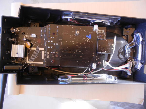
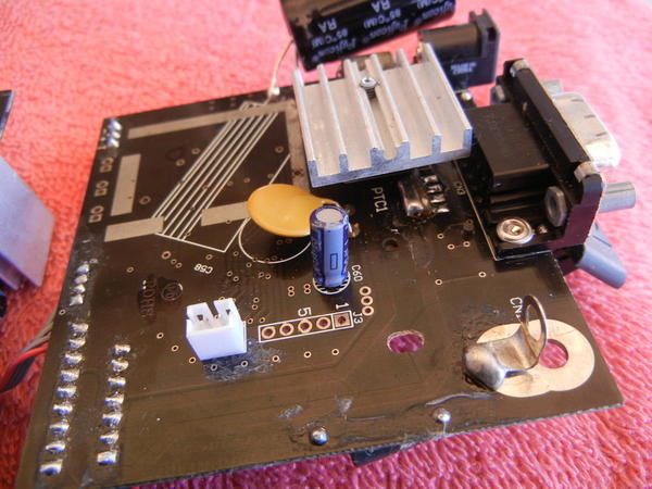
The entire post was coming unscrewed from the base. I fiddled with it, trying to get it screwed on tight, and as I did, I noticed some near normal values flash by on the meter. When I finally got it screwed in all the way, the readings were back to near zero. I finally think this thing is ready for a "vacation" at Lionel.

In the meantime, I have no problem getting by on TMCC. I've been doing that forever, no big deal. Even with just TMCC, the track signal debugging can proceed.

Here's a question: When the TMCC and Legacy bases are both in use via the "Y" cable, is it possible that only the TMCC base is doing the work and the signal is just passing through? This might explain some of the results if that was possible. If it's not, then the Legacy base was working at some capacity, but far from full. Or, maybe I just got lucky and hit a sweet spot during the test.

I did one other test, an earth ground network quality test. I just measured the resistance of the conduit over about a 100' length. It measured .3Ω. That's probably close enough to zero to say that any ground plane wires tied to it will have about the same potential. Ie, it's a 100' terminal strip and I can tie to it anywhere with confidence.

Assuming your Y cable is correctly built and labeled, the TMCC Base passes the normal serial-output signal from the CAB-1 to the Legacy Base on one of the Legacy Base's 4 I/O channels.  The processor in the Legacy Base incorporates that information with any data that is coming from the CAB-2 and anything else on the other three I/O channels and generates a composite "Track" signal.

Thanks for the peek inside Dale. This seems like a fairly simple thing to check, but I'm not sure if that would void the warranty  (if I even still have one after all this time). I'm thinking it's worth a look before I send it away.

The TMCC base read 1570 no load, and 633 layout connected. I assume those values are OK.

That's interesting. It means that as previously observed, the Legacy base was working at some level, as demonstrated in the second video with the test track and the Cab-1 controlling the engine, and later with the engine on the layout in the final configuration.

Last edited by Big_Boy_4005

If you take it apart, leave it upside down and you won't have to fiddle with the stuff that falls out. But put some sticky tape on the little button on the bottom so it won't fall into the works. I think the post is a double nut, first tighten the post to the case and then tighten the nut to hold the ring for conduction. 

So far the warranty for the Legacy base and Cab2 seems to be lifetime but you need your invoice copy and you have to send the base and Cab2 in together. Since your base is 3 years old, there is an update for the charging circuit that needs to be done as well.

Chuck, that being the case, with charger update, maybe it's just better to let them do everything. An invoice may be hard to come by, I picked it up NEW off the bay. However, I believe I registered it. So if I did, they should have it on record.

While they're at it, will they load the latest software? If not, I'm planning on moving my computer to the center of the room next to the bases, so I can plug in the bases and the C/MRI. I can load it.

Elliot,

My Legacy base is a Cab 1L. One of the features is the ability to adjust the signal operating frequency in case there is a competing signal in the area like WiFi. From your Dale-o-meter measurements it sounds like a defect but I was wondering if something like frequency adjustment is part of your Legacy base.

S

I had the Legacy Base signal output lug nut come loose on the inside of the base.  Of course it happened near the beginning of a club meet.  My engines on a storage track in the back room took off like mad.  Took me a few minuets to figure out what was going on.  Took the bottom off the base and tightened it up adding a lock washer.  Never a problem before and not a problem since.  Easy fix but under heavy duress. 

Dan

Last edited by loco-dan

How about a home made Signal tester? Something like a coffee table about 4 feet long,2 feet wide, Maybe a foot or so high with a  wire zig- zagged on the bottom with a wire lead and an  alligator clip   to clip on the earth ground.  . Something really light that you could move around very easily and clip on to the wall outlet's earth ground.  . Nothing fancy perhaps even  made from a card board box.

Just place it over the engine  instead of your hand.  


Last edited by Gregg

Yeah John, I need one of those too. I've even got a donor board in mind. I have that discussion marked so I can go back to it. Pin 13 converts the signal strength to voltage, then read the meter?

Let's see if I can get this base fixed today, put that thing to rest once and for all.

Finally, this has been a fantastic discussion of TMCC and Legacy. I know I've learned a lot, and dispelled a few myths along the way with all the tests. As I've said repeatedly, the upper deck signal isn't a problem. The lower deck signal used to be better, but now it is spotty. So, what changed? Answer, the chicken wire or maybe just the whole upper deck in general.

We are dealing with AM radio here, and we all know what happens when we go under a bridge or into a tunnel in our car. Even though the the chicken wire is connected to earth ground, it is not enhancing the signal, it is killing it in spots, and most of those spots are fairly deep under the upper deck. I'm just going to have to reintroduce the signal in the form of some ground plane wires.

Thoughts on my latest theory? Let me hear 'em guys!

George, there are no 3 rail clubs in this area. I'm aware of the NJ club and their successes in this arena and have the contact info for them. The solutions are definitely out there, it's really more a matter of choosing the right ones and implementing them. Deep down, I'm not worried. I'm confident that I can make this work. I will succeed where Tommy Z could not and switched to DCS as a result. Not an option!

Big_Boy_4005 posted:
Matt Makens posted:

Well, Ive said it before, if I was building a layout that large 3 rail or not, I would have used DCC. It is proven to run layouts that large.

Convert all those engines? You've got to be kidding. I've come too far to turn back now. Maybe on my next layout. Or better yet on yours.

DCC is great but that would be insane if you have 50-100 engines+ to convert. DCS might be the way to go. Also how about contacting Mike Reagan at Lionel or a tech guy at Lionel, USA.

The car comes from the NJ-HR club, and they used it to sort out their signal issues.  I recall them saying when the signal was in the 40's, everything was great.  When the signal dropped down past about 30 and lower, the wheels started to fall off.  Bob De Guarde or Chris Lord at the NJ-HR are the folks to talk to, they were intimately involved in sorting out the signal issues there.

No George, DCS is a non-starter in my world. Again, it would mean convert the fleet, but beyond that, it doesn't do what I want to do. I have always hated its proprietary system since it was first introduced, and swore never to buy it. In spite of how nice MTH engines look, unless I can get them cheaply enough and convert them, you won't find them in my world.

To do what I want to do, I NEED THE CODES to run the trains. TMCC has always been open, and now Legacy is too. JMRI has the TMCC codes already incorporated into it, just like the DCC codes. I'm not sure if they've gotten Legacy in, but for what I'm doing simple speed control is the only function I need. My end goal is to have the computer be able to run mainline trains in a live action simulation. Nothing pre-programmed, just reacting to signals as if a human was controlling the train.

When it comes to talking directly to Lionel about my signal issues, the NJ club has already done that legwork. Chris Lord has graciously shared their findings here on the forum. I have read that material a few times, and again have the topic marked so I can go back to it. You won't find me participating in a wide range of topics here, but if it has to do with TMCC signal, I'm all over it, even if I'm just listening.

All that time converting all those engines as opposed to spending dozens of hours trouble shooting the issue, dozens more hours researching the solution and then dozens more hours implementing the solution that may or may not work.

FROM THE WEBMASTER:
PERSONAL AND UNCALLED FOR STATEMENT EDITED OUT. Matt, keep your personal opinions about Elliot to yourself. This is not the place...

That was a factual statement, not a personal opinion

Last edited by Former Member

Elliot, With all the great work I see in your layout, I'd like to see you pull that base apart, tighten that nut and hopefully put this to rest. I did this for a friend after reading about this on the forum and it fixed his signal problem. I then sent the system in because the pulsing blue light quit and Lionel fixed it for free with no questions asked and no receipt. Watch for the loose parts though. I'd like to see you get all you can out of that beautiful layout!

gunrunnerjohn posted:

No offense Matt, but suggesting a wholesale conversion to DCC is a pretty lame suggestion.

I got the impression after reading Matt's first post was that he was saying from the outset he would have used DCC. I agree with that but suggesting to convert 50+ locomotives is definitely out there in my humble opinion. No offense Matt. At this point Elliot has to stay the course and hopefully he can get the system to work. I had similar problems when I had a 3 rail layout in the early 2000s. It was very frustrating. DCC has its cons too but if you have power you have the signal. That's what I like best about DCC. 

Good luck Elliot. I wish you the best in figuring this thing out. 


gunrunnerjohn posted:

The car comes from the NJ-HR club, and they used it to sort out their signal issues.  I recall them saying when the signal was in the 40's, everything was great.  When the signal dropped down past about 30 and lower, the wheels started to fall off.  Bob De Guarde or Chris Lord at the NJ-HR are the folks to talk to, they were intimately involved in sorting out the signal issues there.

40 millivolts ac?

Thanks John. As you probably know Matt and I go back a ways, as he had been helping me with the layout. I don't really recall him suggesting DCC, but he probably did, and it just went in one ear and out the other. It tends to register better in writing, as in "send me a memo". You're right, it's not particularly constructive or on topic for this discussion.

For the record, I'm in my mid 50's, my health isn't the greatest, but I am financially stable. There are even more reasons that I don't do traditional work, but those are enough. There was a time when I did work for a living, but those days are behind me. I consider this layout my work, and after a 6 year hiatus, I am trying to reestablish some kind of a work ethic.

One thing I would like to point out here is, that I owned almost every one of those locomotives before I even met Matt. His suggestion no matter when he made it, was already after the fact.

Last edited by Big_Boy_4005

I was unaware that you planned to use computer control, Elliot, and am very interested to see what you'll be doing.  I fully agree that the inability to talk to DCS from the outside world is a major drawback in the system.  I think one could probably get in through the back door now, with the wifi control module, but I'm not sure how much of that protocol is open to third parties at this time either.  As for DCC, it seems a fairly good system from what little I know, but I don't see much point in converting everything to DCC from TMCC.  Since it seems that the TMCC base works pretty well, I think the legacy problems will get sorted out eventually.  

As far as signal issues with TMCC, I think such a large and complex layout is bringing up things that were simply not tested for in the design of the system.  I wonder if the folks that are a bit more knowledgable about the system could input on the possibility of designing a signal amplifier, not just for the track side output but that boosts the ground plane side as well?  The idea that GRJ suggested that the amount of track causing capacitance issues seems plausible to me and I wonder if this could be overcome by boosting the output stage of the Legacy base? 

JGL

Great news!!

The base is working. What would normally take most of you guys 15-20 minutes, took me more than an hour, but I got it. Yes the nut was totally loose. Of course as I was putting it back together, one of the wires broke on the charger switch, so I soldered that back on. Thanks for the hint about the button. That saved me some headaches.

Dale, the numbers are in: 1982 no load and 976 with the layout connected. I think we have a winner!!!!

With this resolved, I can move on to track debugging which should be a little more academic. I know that if I place a wire above the track, it will work. The trick is to get the signal without making it ugly. And no, I don't run electrics so please don't say catenary.

Chuck, I totally agree that the challenge is part of the fun here. On my left forearm I have a tattoo that says " NOTHING IS EASY". If it was everyone would do it. There is a real sense of accomplishment when we can make things work, and maybe more so when we test the theoretical limits of an engineered product.

There will be more challenges with this railroad, I have no doubt of that.

Big_Boy_4005 posted:

Great news!!

The base is working. What would normally take most of you guys 15-20 minutes, took me more than an hour, but I got it. Yes the nut was totally loose. Of course as I was putting it back together, one of the wires broke on the charger switch, so I soldered that back on. Thanks for the hint about the button. That saved me some headaches.

Dale, the numbers are in: 1982 no load and 976 with the layout connected. I think we have a winner!!!!

With this resolved, I can move on to track debugging which should be a little more academic. I know that if I place a wire above the track, it will work. The trick is to get the signal without making it ugly. And no, I don't run electrics so please don't say catenary.

Chuck, I totally agree that the challenge is part of the fun here. On my left forearm I have a tattoo that says " NOTHING IS EASY". If it was everyone would do it. There is a real sense of accomplishment when we can make things work, and maybe more so when we test the theoretical limits of an engineered product.

There will be more challenges with this railroad, I have no doubt of that.

Telephone or power poles for the ground wire?


I've thought of poles, I'm not sure what kind of lateral reach the signal would have, ie how many tracks can one wire cover.

IMG_6280

I just added this structure yesterday. It runs right down the middle of a trouble spot. It will be very easy to add a wire here. The trick with poles is keeping them out of the way, so they aren't getting snagged.


Attachments

Images (1)
  • IMG_6280
Big_Boy_4005 posted:

I've thought of poles, I'm not sure what kind of lateral reach the signal would have, ie how many tracks can one wire cover.

IMG_6280

I just added this structure yesterday. It runs right down the middle of a trouble spot. It will be very easy to add a wire here. The trick with poles is keeping them out of the way, so they aren't getting snagged.


Before you do a lot of work, I would try a wire along the top of the wall on the right...just to see.

Mike Reagans TMCC/ Legacy signal video  recommends running the ground wire along the tracks, between parallel tracks. Go to 12:40 on this video https://youtu.be/UQ-hiIvPxVs

Earlier in the video it discusses the signal interference of over and under trackage

I'm under the impression your chicken wire keeps the lower level from interfering with the upper, but it doesn't solve the parallel tracks ground plane issue.

I'm no expert, just "cobbling together" information I've gathered from other sources.


Last edited by RickO
NYC,SUBWAY TRANSIT SIGNAL posted:

Love your layout.

Good Luck, John 

Thank you John. I do love the NYC subways. Last time we were there, we did some serious riding. What I'm modeling is Minnesota local.

Rick, I have those wires throughout both hidden yards, as well as along some of the mainline on the lower level. I need to revisit those, because some seem less effective than others.

I have seen Mike's video many times, just not recently. I think I've found that a wire placed higher rather than lower, works better. One of the things that that was supposed to combat was conflicting signals from parallel tracks of different lengths. I really don't have situations like that, because every section of the layout shares the same ground wire, so there is only a single signal on all parallel tracks. It seems like it's more about the antennas finding the airborne component, which is why the higher wires seem more effective.

I'll keep working on it.

Very glad you got the legacy base sorted out, Elliot.  This has really been a great thread with lots of knowledgable people sharing their experience and wisdom.  Thoroughly enjoyable to follow along.  I'm looking forward to seeing how the signal issues are solved.  

For clarification, you have chicken wire laid out under the plywood on the upper level, and that level is working without issue, but on the lower level, up to this point you have only the conduit of the 120VAC lines acting as a ground plane source?  I understand that an overhead wire is probably the best solution to provide the strongest signal, but have you tried perhaps stapling some chicken wire to the underside of the layout in the trouble areas? (or perhaps using spray glue and aluminum foil?) My brain is thinking if it works in one level, it may provide enough signal in others.  Then again, it may be that with six parallel tracks the track signal side will wash out the ground plane side with it radiating from below.  Again, just tossing out ideas to which more experienced folks may already know the answers.  

JGL

Thank you Nick. Patience and persistence are the words of the day. There were those who just said send it in. I'm glad I toughed it out a bit. If you look back on page 4, near the middle, that's where the diagnosis came together. After that, the surgery was easy. This has been a fun topic, getting a lot of people involved, and thinking out in the open.

This isn't the end of the story though. There's a lot more to be done to get everything running smoothly. I just ordered a cheap AM radio off eBay to do one of Dale's tests. Should be here next week. 

Thanks JGL. I was actually thinking about adding some ground plane material under there to see if it helped. The nice part about the upper deck was it was built in during construction. Retrofitting is a pain, because all the wires and Tortoises are in the way now. 

Have you ever seen a picture of the small helix? Best signal anywhere on the layout, because I lined it with foil, and built the ground plane in. The big helix was recently retrofitted with a single wire all the way up. It works pretty well too now.

IMG_1155

Now that the legacy base is fixed, I think I'll change the topic title one last time, to something we can run with...

Adventures in TMCC & Legacy

Attachments

Images (1)
  • IMG_1155
RickO posted:

Mike Reagans TMCC/ Legacy signal video  recommends running the ground wire along the tracks, between parallel tracks. Go to 12:40 on this video https://youtu.be/UQ-hiIvPxVs

Earlier in the video it discusses the signal interference of over and under trackage

I'm under the impression your chicken wire keeps the lower level from interfering with the upper, but it doesn't solve the parallel tracks ground plane issue.

I'm no expert, just "cobbling together" information I've gathered from other sources.


RickO,

I learned in another thread where a club was losing signal in one curve, that the elevated wire is the more effective method. There were some notes from Jon Z., perhaps posted by NJ Hi-Railers in working out their signal issues. If I find that, I'll post the link.

One thing of note with a large layout.  If you have too much "antenna" area and get excessive coupling between the track signal and the ground signal, that could result in a lower amplitude signal from the base due to excessive loading.  I suspect if you measure the capacitance between the outside rail and the ground plane, you might be surprised how large a value it'll be.  Obviously, this measurement would be with the command base disconnected.

gunrunnerjohn posted:

One thing of note with a large layout.  If you have too much "antenna" area and get excessive coupling between the track signal and the ground signal, that could result in a lower amplitude signal from the base due to excessive loading.  I suspect if you measure the capacitance between the outside rail and the ground plane, you might be surprised how large a value it'll be.  Obviously, this measurement would be with the command base disconnected.

My exact thoughts this AM. First of all the use of the term "ground plane". It's just a wire (connected to the house ground wire), in the air, over the track the engine is running on. The use of a large surface area like the chicken wire or large area metal foil seems like, as GRJ points out, a large capacitance between the track and the in the air ground wire. Which would reduce the amplitude of the signal.

I have asked Elliot to disconnect some of the earth-ground mesh to see how much the signal amplitude increases so that we can better understand the loading effects.

I suspect that the chicken wire is so close to the upper track that the effective radiation downward from the mesh is weakened.  More testing to come....

Big_Boy_4005 posted:

"Thank you Nick. Patience and persistence are the words of the day. There were those who just said send it in. I'm glad I toughed it out a bit. If you look back on page 4, near the middle, that's where the diagnosis came together. After that, the surgery was easy. This has been a fun topic, getting a lot of people involved, and thinking out in the open."

Now that the legacy base is fixed, I think I'll change the topic title one last time, to something we can run with...

Adventures in TMCC & Legacy

Curious, would this have been solved much sooner if a known good Legacy base was substituted since the TMCC base functioned? Nice layout and construction thread.

Last edited by BobbyD
BobbyD posted:
Big_Boy_4005 posted:

"Thank you Nick. Patience and persistence are the words of the day. There were those who just said send it in. I'm glad I toughed it out a bit. If you look back on page 4, near the middle, that's where the diagnosis came together. After that, the surgery was easy. This has been a fun topic, getting a lot of people involved, and thinking out in the open."

Now that the legacy base is fixed, I think I'll change the topic title one last time, to something we can run with...

Adventures in TMCC & Legacy

Curious, would this have been solved much sooner if a known good Legacy base was substituted since the TMCC base functioned? Nice layout and construction thread.

While this makes sense and I do agree. Sometimes it's just not that easy. I have my Legacy set away for repair at the moment. My issue was LCS operations so different from Elliot's problem.  It could have been quickly diagnosed with a spare Legacy set. However I only know of around 6 Legacy sets in the whole UK! Arranging to borrow one would have been a bit tricky.

I guess I could spend $300 and have a spare sitting in a drawer. But I have a spare TMCC base for a backup. 

I would like to see a diagnostic utility built in to the LSU software. So you attach your base to the serial/USB lead and your PC and it automatically checks everything is within operating limits. Might need some sort of special lead so it could check the output on the terminal so it could diagnose an issue like Elliot had. 

Nick

Add Reply

Post

OGR Publishing, Inc., 1310 Eastside Centre Ct, Suite 6, Mountain Home, AR 72653
800-980-OGRR (6477)
www.ogaugerr.com

×
×
×
×
Link copied to your clipboard.
×
×