Hi guys, great conversation going here, keep it up. I'd like to see this topic end up being THE PLACE to come do discuss everything related to the 455Khz signal. That's why I'll be transitioning the title to better reflect what the conversation is all about.
My layout is an interesting testing ground with plenty of quirks and mysteries to solve. There are lots of theories out there on how to make our trains run better, and with any luck we can prove or disprove many of them in this thread.
I am not a "scientist". I do not have the electronic background or education that some of you have. What I do have is a general understanding of many of the concepts, which I have picked up from many of you over the last few years. I also have a willingness to learn and try new ideas based on your suggestions.
I had a wonderful phone conversation with Dale last night. We talked about more tests that should be done as well as my grand layout control scheme and how it was all going to tie together with C/MRI, JMRI and TMCC/Legacy to create a fully automated CTC mainline. The theory for all of it is quite sound, as most of those components have been around for a long time, and are well tested. The secret to reaching the end goal is perfecting the track signal for smooth, RELIABLE operation.
Sorry I got a little behind in replying to your responses this morning, there were so many, I got a little overwhelmed.
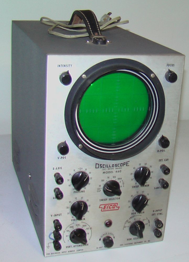
Dale, the radio should be here next week so I can do the sweep (and check some locos![]()
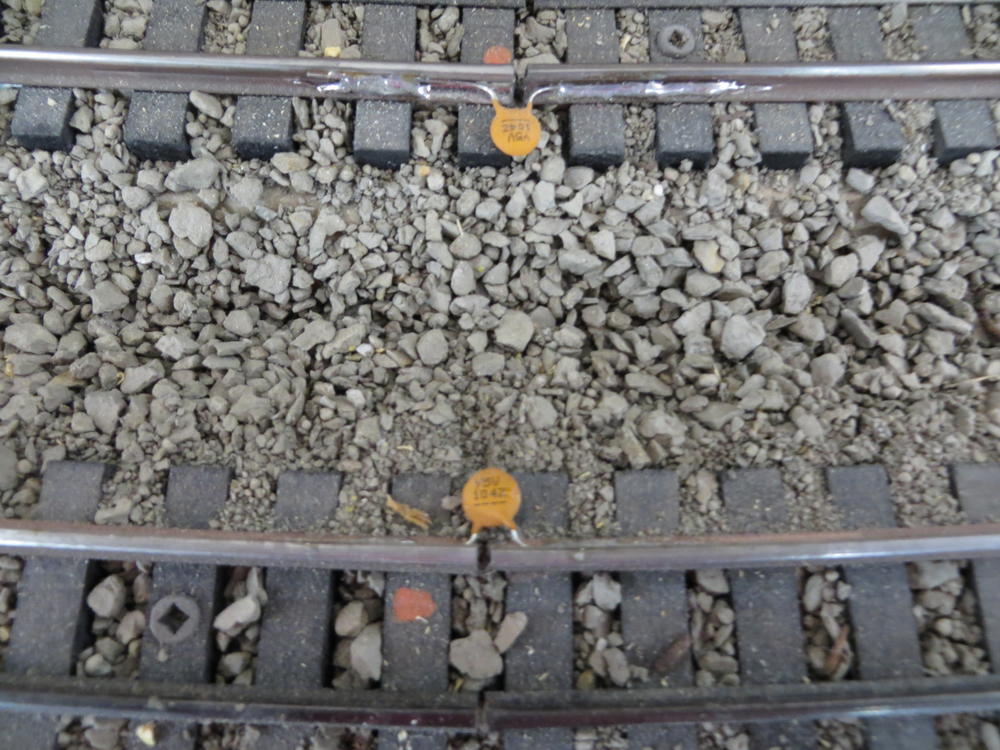
![]() ). I have to reconnect the bases and track power, in order to do the chicken wire disconnect test.
). I have to reconnect the bases and track power, in order to do the chicken wire disconnect test.
Chuck, maybe we should try to rename the term "ground plane" to something like "earth ground carrier". It would be more accurate and descriptive.
BobbyD, Nick is right, another Legacy base would not have been the answer for this problem. All that would have said was one base worked and the other didn't. This was all about probing the bad base to figure out what made it bad. The fact that it was intermittently bad, made it confusing on one level, but also made it possible to ultimately pin down the problem.