1.  Normal 027 tubular track setup on a small 4 x 8 layout (inner and outer loop), Lionel postwar 2026 engine and 6466W tender, KW transformer

2.  Added a Lionel steam sound car which came with the #6-5906 sound activation button

3.  All center rail track taps from the layout are supposed to route through the sound activation button (which they are) to the variable post (A) or (B).

4.  I had replaced the whistle diode in the KW with a 6A10 diode as per these instructions

https://dfarq.homeip.net/lionel-kw-diode-upgrade/

5.  When the whistle handle was activated only the whistle in the tender blew (not the whistle in the sound car) and the bell in the sound car would come on.  Every time.  The engine sped up (as it is supposed to).  The bell would continue ringing until the sound activation button was pressed for 2 seconds or more, or the whistle handle blown for 2 seconds or so.  Button depressed for two plus seconds resulted in the engine slowing down or stopping because of the center rail drain.

6.  Two of those diodes in a row blew (heated up and fractured with a burnt smell) after a week or so in between them.

7.  Because two 6A10 diodes blew up, I Installed a 40A stud mounted diode instead (yesterday).  1N1186RA  200v  40A

Like this:

http://www.tranz4mr.com/KW_Whistle_Diodes.html

8.  Now both the whistle in the tender and the sound car are activated simultaneously with the KW whistle handle and the bell is activated with the #6-5906 sound activation button.  ???  And when the button is pressed the engine slows down to a crawl or stops as before.   If you run the engine at high speed (which I hate) you can hear both whistles.  Slow it down and you hear the 6466W tender whistle motor laboring and the whistle in the sound car dominates.  There is a lingering of the sound car whistle (maybe that's normal).

9.  There is no difference and has not been if I reverse the sound car on the track.

I am concerned that with the heavier duty 40A diode other components will burn up instead.  What am I doing wrong?

John

Last edited by Craftech
Original Post

Replies sorted oldest to newest

First off you had the original diodes installed backwards.

Now, the diode is installed correctly, everything is working correctly.  The KW is sounding the whistle as it should, both whistles. The 5906 is operating the bell and the 6466W whistle, normal operation.  The 6466W is not polarity sensitive, so will sound with any sound button in any orientation... it was not anticipated that somebody would be using a sound car, and a traditional whistle in addition, on the same train, which is what you are doing.

@ADCX Rob posted:

First off you had the original diodes installed backwards.

Now, the diode is installed correctly, everything is working correctly.  The KW is sounding the whistle as it should, both whistles. The 5906 is operating the bell and the 6466W whistle, normal operation.  The 6466W is not polarity sensitive, so will sound with any sound button in any orientation... it was not anticipated that somebody would be using a sound car, and a traditional whistle in addition, on the same train, which is what you are doing.

Oh.  I just went by the article and the photo.  Now it makes sense.

I take it the power drain is normal when you activate the button because of the daisy chain to the center rail?

That prohibits low speed operation (not the greatest on those old AC engines to begin with).  Any workarounds?

Thanks,

John

@Craftech posted:

I take it the power drain is normal when you activate the button because of the daisy chain to the center rail?

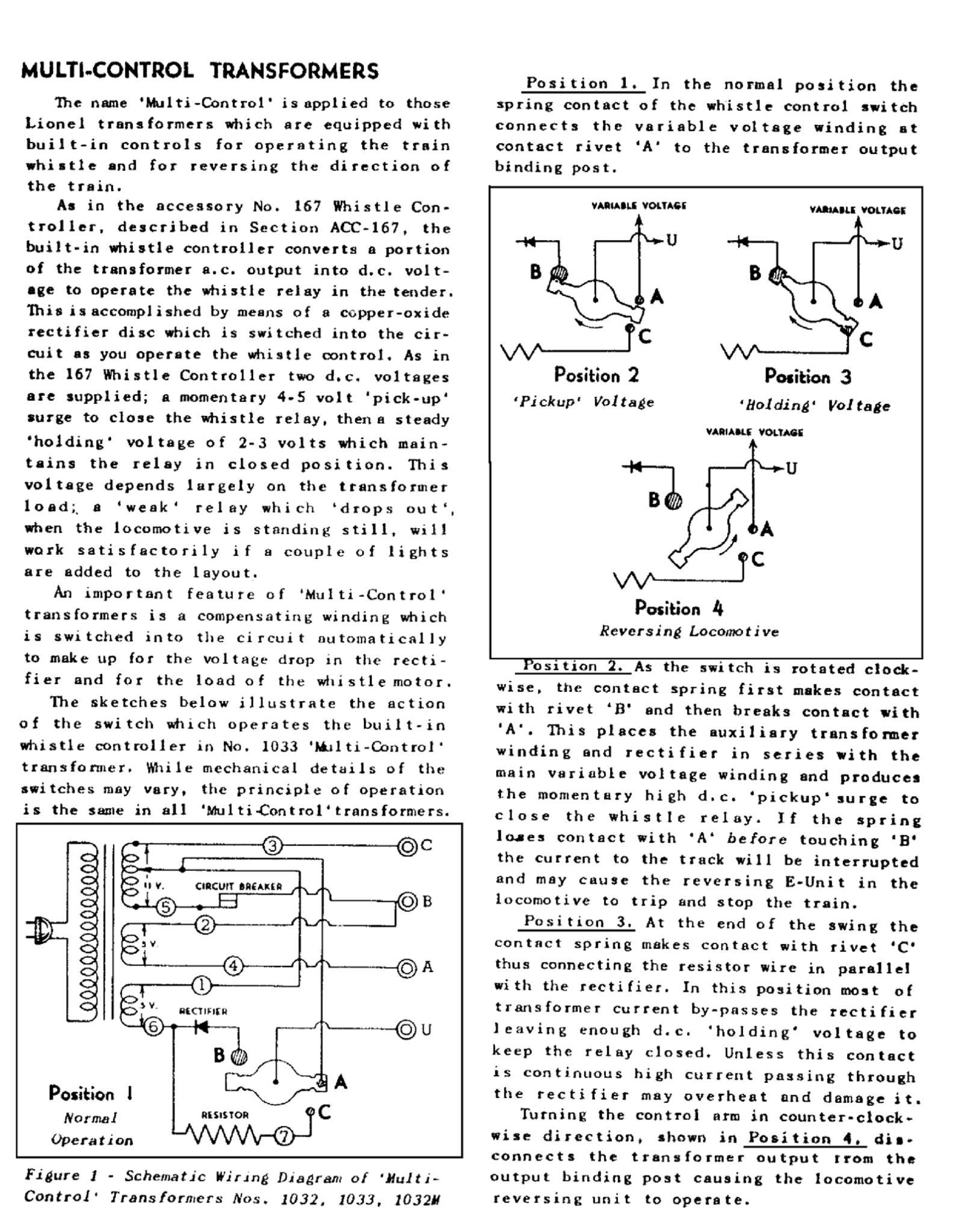
Use of the 5906 button does not have the 5 volt compensation winding that the train is expecting like it gets from the KW when the whistle control is activated. The 5906 is typically used where the need for that 5 volts is not there as there is not an extra motor(the whistle motor) running at the same time as the locomotive motor. Here is an excerpt explaining the compensation circuit in Lionel transformers.


Thanks Rob.  I get it.  I saw some older posts about this and suggestions of DIY sound activation boxes, Zener Diodes,  or TWO Lionel buttons, but not sure if anyone had success with this problem.


Also, in terms of the diode being backwards in that article I followed.  I tested the 6A10 diodes (that blew up) and the 1N1186RA that's in there now and the polarity is indeed reversed in each.  Cathode is grounded in the article with the 6A10 and the Anode is grounded with the 1N1186RA right now.  I would have thought Cathode was ground in the KW.  


John

Last edited by Craftech

The schematic Rob provided shows the resistor wire soldered to the cathode of the rectifier.  That is the way  it was before I bought the stud diode.  See photo:

Two of those blew up.  They were rated at 6A.  Rob said they were backwards.  The stud diodes I bought ended in RA that means the large metal part with the threads is the ANODE and the solder end is the cathode.  Those are now in there and the whole thing is smoking from blowing the whistle.  Some of the stud diodes people install are reversed with the threaded portion the cathode.

Which is right?  In an AC application (like the original setup with the motorized whistle tender) I don't think polarity was an issue.  The sound car is a modern device like the newer engines that have DC components so (as far as I know) DC polarity alternates between the whistle and the bell.

Also the 1033 center rail goes to the U terminal and on the KW it goes to the variable A or B posts so I am not sure about the schematic above when it comes to the KW.

I think.

Last edited by Craftech
@Craftech posted:

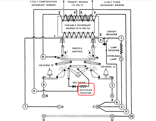
The schematic Rob provided shows the resistor wire soldered to the cathode of the rectifier.  That is the way  it was before I bought the stud diode.

Well, I was wondering when you were going to mention that. It's a common trap to fall into, as nearly every schematic that Lionel printed(that I'm familiar with) shows the wrong orientation of the whistle rectifier, which would lead to your initial experience.

Of course, the polarity didn't matter until after the 1972 introduction of the electronic whistle, which is polarity sensitive.

@Craftech posted:

UPDATE:  Blew the whistle three times in a row and the transformer started smoking.  I opened it and the 40A whistle diode was hot.  Something is not right just as I feared.

It appears that you may have severed the shunt resistor or left it out of the circuit, as only a portion of the current(enough to keep .85-1.1 volts DC on the track) is supposed to go through the diode in the "hold" position. Still a 40 amp diode should be able to run a train w/o a problem, so there may be another factor in play.

Shunt

Here is the resistor in the KW:

KW6

Attachments

Images (2)
  • Shunt
  • KW6
Last edited by ADCX Rob
@ADCX Rob posted:

Yes, anode to case.

I'm not sure what the spec is for the resistor, but that should be close. Is it still in the circuit properly(shunted around the diode)?

Yes, it is wrapped around the diode mounting plate.   I noticed now (after the smoking) that the loco no longer speeds up when I activate the whistle lever.  That's new since the smoke.  I used jumper wires to try the diode in reverse and the same thing - Additional compensation voltage is no longer being applied to locomotive when whistle lever is activated.


John

Attachments

Images (1)
  • IMG_1114
Last edited by Craftech

Here is where I am with this.

1.  Replaced the diode with a 12V, 50W Zener Diode (based upon looking at every post on this forum that dealt with KW / Sound Activation button).   Solid State 1N3311B ( Newark Electronics SKU # 10P4804)

2.  Changed the asbestos coated nichrome resistor wire with a 1.5 Ohm, 25W, 5% Tol. wirewound.  There was a debate as to whether or not a resistor was needed with a Zener so I opted to leave one in.  Ohmite Part # HS251R5J (Newark Electronics SKU # 73AC6322)

3.  Changed the 12v 10 A Littlefuse automotive circuit breaker (which appears to have burned out).  I had soldered in pigtails so it was easy.   Didn't replace the circuit breaker resistor wire.

No smoke yet from the transformer, but the button slows the 2026 down to stopping when the button is pressed as well as the whistle tender motor buzzing to try to start when it is pressed.

I may build my own button.  Bought all the parts.

https://slsprr.net/features/SoundBlkProtect.htm

Keep throwing money at this problem.  Good thing I am retired.

IMG_1118

John

Attachments

Images (1)
  • IMG_1118
Last edited by Craftech

Stud mount diodes were/are made 2 ways with the stud being the anode (standard polarity) or the stud is cathode (revers polarity)  by internal polarity chips/pellet mounting

The diode symbol on the seal designates polarity

Perhaps  polarity symbol is wrong

Take simple VOM and check; either high resistance (blocking (VOM battery voltage) or  looks like a short to determine polarity

Another thought is the diode is bad on reverse blocking voltage diode for your 200 v -test room temp voltage (200v-HI POT-or transistor curve tracer) and leakage current should be well less than 1 ma if old technology

1N1186RA  200v  40A as I recall is a reverse polarity unit by industry nomenclature (R) and-stud is cathode

Thanks for the reply.  Much appreciated.  1N3311B  (Zener) and 1N1186RA (Normal diode) have the same polarity.  Both were correctly installed.  When installed in reverse (or the center rail and outer rail leads switched to simulate the same polarity reversal of a diode) the Lionel Sound Activation Button will activate the bell from the electronic sound car and not the electronic whistle in the electronic sound car .  And only the whistle from the old tender will sound from the handle on the KW, but will ALSO ring the bell at the same time.  Then you have to hold down the sound activation button for two plus seconds to shut off the bell.  Turn the handle on the transformer and the bell and (old) whistle sound simultaneously.  That's the problem I was having with the 6A10 (see the first post) installed the way that article I followed incorrectly showed me how to install it (backwards).  They also fried (two of them).   Rob pointed that out earlier in this thread.

When the 40A barrel diodes are installed properly (as they are now) the whistle handle on the KW blows the whistle located in the sound car in position 1 and both whistles in position 2, and the 6-5906 button will only turn the bell on and off.

The drain on the center rail (since ALL center rail power MUST route through the sound activation button) is pronounced and others on train forums have reported this as well.  One of the "solutions" was to substitute that exact Zener diode for the 1N1186RA.  The controversy was whether the resistor was necessary (but not detrimental).   So far the Zener has not prevented or reduced the power drain.  I do like to run my trains at relatively low speed for realism.  Maybe that's the problem.

Some recommended two buttons.  Haven't tried that yet and don't know how to hook them up (series or parallel).  I will take some measurements with a VOM to see if I can get any values that are helpful.  But for now the Zener is exhibiting the same problem as the non-Zener in terms of center rail power loss.

John

Last edited by Craftech

Add Reply

Post

OGR Publishing, Inc., 1310 Eastside Centre Ct, Suite 6, Mountain Home, AR 72653
800-980-OGRR (6477)
www.ogaugerr.com

×
×
×
×
Link copied to your clipboard.
×
×