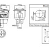
After a suggestion involving using relays, I got some illuminated automotive 12V Round Rocker switches to use in conjunction with relays, where the switches would be powered by a 12V DC power source in order to activate a relay.

How bad of an idea would it be to use the same switches to power sidings where I don't need relays by powering the switch with 18V from my track power transformer?  Would the switch be able to handle the 18V AC from the train transformer?

12v automotive illuminated switch

I really want to incorporate the LED round rocker switches and I can't find any rated for higher than 12V input.

Thanks in advance,

Rob

Last edited by Robertejr
Original Post

Replies sorted oldest to newest

If the illumination is led, the AC could be problematic over time. Also, many of these switches act like a double throw switch. If in the off position when spanned by pickup rollers over the isolation gap from a powered track they give a direct path to ground. That was a tough troubleshoot for me the first time it happened. If you never forget to have the siding powered when entering it with anything with double pickup rollers, no problem. I just left the ground wire (illumination) off. Also, not sure how DC has frequent polarity changes. 

I have been using them for 10 years for sidings. If you tie all the switch  commons together and put a diode (1N4003 or so) in series to your common on the layout, then the LEDs will not suffer the reverse peak of the AC voltage. Also since the LEDs only conduct during half the cycle, the rms voltage on the LEDs will be Vpeak/2 or about 12 volts. So all good. Just don't span a turned off siding with a car or engine with two pickups.

Robertejr posted:

How bad of an idea would it be to use the same switches to power sidings where I don't need relays by powering the switch with 18V from my track power transformer?  

Out of curiosity, if you already have the 12V DC relay "infrastructure" in place, why not use relays?  The incremental cost of a relay is about $1.  Note that your control panel wiring would use low-current 12V DC so the wiring is smaller gauge from panel to the relay that controls the siding power.  As I recall, you were planning to use DCS and have a relatively large layout.  If you run siding power thru the control panel switch then your DCS signal travels over the long run which may (YMMV) affect DCS communication quality.

Otherwise, do as cjack says and add the 5 cent diode.  And be mindful of avoiding driving a consist into an unpowered siding (which would short your track power transformer).


Automotive-spec electrical equipment lives on a whole 'nuther level of existence than our little models - meaning tougher, heavier, weather-proof or at least resistant, monstrously amped-up by comparison. It could probably handle all your locos at once. Think of your "big" Pittman motors - now think of your car's starter motor.

Auto stores can be a moderately good source of things for us. I know an HO'er who re-motors all his locos with remote outside mirror motors from his brother's auto scrap business. Smooth and indestructible in model RRing, and I imagine would do in many O-scale applications. (Some can be coggy; he skips those auto makes. I think he finds the Honda mirror motors to be his favorites.)

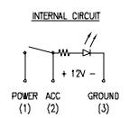
I am not sure I follow the shorting problem.  You have an SPST switch with an LED connected to one side; the LED having a resistor inside the switch sized for 12VDC.  The other side of the LED is brought out to a separate terminal.

First ignore the LED and decide if the switch is OK.  A low voltage switch won't care much between 12 volts and 18 volts.  As mentioned contact arcing is less of a problem for AC because the voltage goes to zero every 8 millisecond which would extinguish any arc.  Since the switch is rated for DC this should not be a problem anyway.  Finally the current rating must handle the load.  Essentially these are the same questions you would ask about the relay contacts if you used relays.

If you are using the switch to bridge the insulated rail into the siding this is no different than running a train into an unpowered siding.  The trouble here is the current is flowing through the internal wires between the two rollers.  Again, this issue is no different if you using relays.  (If you are using an independently controlled supply to the siding you need to worry about phasing and you will have a problem if the siding voltage does not match the main line when you enter the siding.)

Now consider the LED.  You need to consider the current and polarity.  If this were an incandescent lamp the polarity would not matter but the current would be 50% higher at 18VAC vs. 12VDC and could be a problem.  An LED will act as a half wave rectifier so the current won't be much different with 18VAC vs 12VDC.  However the reverse voltage of the LED is an issue.  That is why the series diode is suggested.  The Anode of the external diode should be toward the switch and the Cathode (stripe) should be toward the supply return.  You could use a diode per switch or a common diode - with the latter the diode must be able to handle the current when all LEDs are on.

Note, if the switch is OFF and you run an engine into the siding the LED will illuminate.

I agree with D500 re automotive switches being beefy.  Although I wouldn't try to use one for a starter motor (100 amps or more).  Perhaps 10A is OK.  I only say this because some of today's 10 to 12 Amp power sources.

John - I had a hard time finding a spec sheet for the switches shown but I grabbed this schematic from a similar switch.  When the switch is off there ACC terminal is only connected to the LED.  The LED is essentially showing the status of the siding.

LED Switch

Attachments

Images (1)
  • LED Switch
Last edited by penn station
John H posted:

You have to have a common for the led to light. When the switch is off there is a connection between acc and ground. 

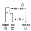
I thought my switches were constructed that way, that the wiper is on power for on and connected to earth for off shorting out the diode and connecting the load to earth. But mine are not. Here is the schematic for my switches...

Siding Switch

My switches are Calterm 40393 12 vdc automotive switches. I bought them from the Farm and Fleet store here in IL.
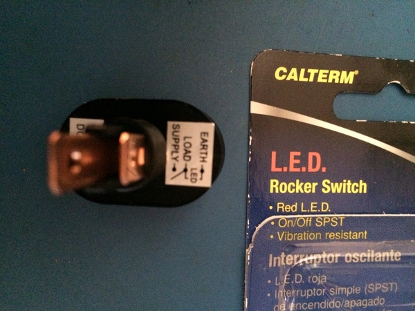
CaltermSwitch2

They say SPST so I should have questioned the shorting or not shorting issue before. I took one apart and it clearly does not short the load to the earth terminal, but it looks like it could have if a little tab was a bit longer. Maybe other brands or versions do, but the #40393 does not. So good on all accounts, mounts in a round hole, good for 10 amps or more, doesn't short out the siding when off, LED illuminated at the RMS voltage of 12 volts when powered with 18 VAC, and somewhat cheap at $4.22 at the Home Depot and elsewhere (just looked it up...).

EDIT: Still good but the schematic is now a DPST as pointed out by Stan2004 since the LED does not light up when applying power to ACC (LOAD) and Earth. The one thing I did not check when I measured with an ohmmeter. Also when I shorted across the turned off block and the live loop track, the block lit up with power and the LED stayed off on the switch. Might have been informative if it lit up...but didn't as Stan pointed out.

https://www.homedepot.com/p/Ca...itch-40393/303616206
Attachments

Images (3)
  • Siding Switch
  • CaltermSwitch2
  • Siding Switch
Last edited by cjack

When the switch is off and your pick up rollers bridge the center rails between main and siding you put track power on Acc which then goes directly to Gnd and your fuse or breaker trips. I went through the same head scratching as described by others above before I finally figured out what was happening. I added relays and all was well and the LEDs worked as I had originally wanted them to. 

Follow the advice of the others above. Save yourself the head scratching and use the relays as Stan described his above post! 

Cjack posted while I was typing, I have a cheaper version of the same switch from Ebay, but it has the identical problems as shown in Cjacks post above. As I recall the conclusion after discussing this here in the past was that these type of automotive LED switches were all similarly constructed and would cause the same problems. 

Woops, I didn't read far enough down, I guess there is one that works properly as per the end of cjack's post above.

Last edited by rtr12
rtr12 posted:


Cjack posted while I was typing, I have a cheaper version of the same switch from Ebay, but it has the identical problems as shown in Cjacks post above. As I recall the conclusion after discussing this was that these type of automotive LED switches were all similarly constructed and would cause the same problems.

But the Calterm 40393 does not short the load to ground. It's truly an spst. I would still measure with an ohm meter, but the 40393 switches I have do not short.

EDIT: It doesn't short the load to ground, but it's a DPST actually. Read the rest of the thread...

Last edited by cjack

Thank you for the excellent information.  Not sure what I'd do without these forums!

Stan you're 100% right.  I was only considering not using relays at spots where the switch, terminal block coming off the TIU, and siding were all relatively close together and wire length wouldn't be an issue for DCS signal.

I'm just coming to the point now where I need to install my first relays, so hopefully after I have done a couple I won't be so concerned about how hard they are to do.

penn station posted:

...

Note, if the switch is OFF and you run an engine into the siding the LED will illuminate.


cjack posted:
...

But the Calterm 40393 does not short the load to ground. It's truly an spst. I would still measure with an ohm meter, but the 40393 switches I have do not short.

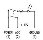
The two automotive switches shown in the OP's photo are sitting right in front of me.  With the switch in the OFF position, applying 12V DC to ACC and GROUND do NOT illuminate the internal LED!

So these 2 behave like a DPST switch.  Perhaps like this:

LED%2520Switch

If you have one of those Calterm switches lying around, you might try applying 12V DC to the ACC and GROUND with the switch OFF.  

So perhaps there are different variants of these automotive 12V DC illuminated switches.  I don't know the fine details about automotive electronics, but I can imagine an application where you want to "short" the load when the switch is OFF...say if driving a DC motor this would rapidly stop the motor by shorting the windings and also eliminate the large potentially damaging voltage spike when instantly removing current to an inductive load.  Again, this is conjecture based on ignorance!


Attachments

Images (1)
  • LED%2520Switch

I think you are correct with the DPST. I did try to illuminate the LED and it appears to not be connected when the switch off. The contacts inside are somewhat complicated...not a simple looking contact setup...probably clever if I figured it out. I'll modify my schematic to a DPST.

Well, I never thought this could get so complicated.  It is humous and frustrating at the same time.

I searched for the Calterm 40393 part and this plus several older forum threads came up with essentially the same discussion and same posters.  I could not find a datasheet but the sticker in CJACK's photo shows the circuit and should work as I described.

Next I did another search for switches like those in Robert's photo.  I looked at Mouser, Digi-Key, Newark, and Jameco.  All the SPST switches were like my diagram or an isolated LED.  All the two pole switches had four terminals and could be wired similar to the SPST.

I am mystified.  I guess I am stumped without knowing the exact switch John is using.

Hey John - Upstate New York is north of Westchester, right?  I am from LI but went to college in Potsdam - some of my classmates considered Upstate to be north of Syracuse.

Cam


C&K

C&K 2

Cherry

Cherry

Multicomp

Mullticomp

Attachments

Images (3)
  • Cherry
  • Mullticomp
  • C&K 2

The amperage flowing through the switch damages the contacts long before voltage.     This means that if the train in the siding is stopped and not drawing any or much power, there is not load on the switch when you make and break contacts.    The ratings and the problems occur when making and breaking (opening and closing) the contacts.    And automotive applications are much higher amperage generally than model RR so eh contacts would be rated much higher for our appliations.

And example ot this is for years I used rotary switches from Radio shack for block control on my layout.   I used the 2 pole 6 position switches and they are rated at .3 amps for making and breaking.    I don't know the voltage rating.   Anyway I still have at least 2 dozen in service on a 3rd layout and I have never burned one out going through AC, a couple of DC systems, and now a DCC system.    

So bottom line I think the automotive switches will work fine for control.  

Robertejr posted:

...I was only considering not using relays at spots where the switch, terminal block coming off the TIU, and siding were all relatively close together and wire length wouldn't be an issue for DCS signal.

I'm just coming to the point now where I need to install my first relays, so hopefully after I have done a couple I won't be so concerned about how hard they are to do.

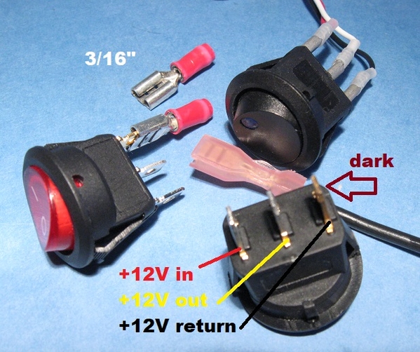
12V DC automotive switch for AC siding block power

I get it.  If you have a lone siding out in the back-forty, you might not have or want to run 12V DC infrastructure wiring for the sake of the relay.  As cjack suggests, install a 5-cent diode (e.g., 1N4003) to protect the internal switch LED when used in an AC environment. 

Attachments

Images (1)
  • 12V DC automotive switch for AC siding block power

Add Reply

Post

OGR Publishing, Inc., 1310 Eastside Centre Ct, Suite 6, Mountain Home, AR 72653
800-980-OGRR (6477)
www.ogaugerr.com

×
×
×
×
Link copied to your clipboard.
×
×