
Good evening everyone!  I'm wanting in install the ERR cruise commander in a K-Line K4 that has TMCC and cruise control.

I'm trying to identify the function of all the wires that terminate in my ver. 4.0 K-Line driver board so I know where to install them in the cruise commander.

IMG_1677  

There is a black molex connector with four wires for AC input and the motor positive and negative terminal, that one is easy.  

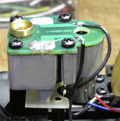
There is a 4-pin plug with a black and white wire.  What purpose do these two wires serve?  Black wire goes to R2LC board, the white wire terminates at the tether pcb.

IMG_1678

There is a 3-pin plug with black, yellow, and red wires that go directly to the motor.  Where would I connect these on the cruise commander?

IMG_1679IMG_1679

There is black wire that is soldered to the bottom of the board, this goes to the motor as well. 

IMG_1680

Attachments

Images (4)
  • IMG_1677
  • IMG_1678
  • IMG_1679
  • IMG_1680
Original Post

Replies sorted oldest to newest

I'd just trace the wires and ring out to the R2LC socket to see which pin they are connecting to.  I know that some of the K-Line stuff generated the chuff from the cruise board, so one could be the chuff.

Note that K-Line didn't use the PWM outputs from the R2LC on their cruise board, so you're going to have to wire them yourself as the CC-M will need them.  There is probably an unused 4-pin connector on the mother board that has those outputs on it.

You won't need these wires, the sensor is unused for the CC-M.

You don't need this wire either, just remove it.

Dumb question, why are you replacing the K-Line cruise?  The 4.0 version is generally a pretty good performing unit.

Attachments

Images (2)
  • mceclip0
  • mceclip1

I've been out of town all week for work, so there's been no time work on my project until now.

The only part I'm confused on is the black wire that terminates in the 4-pin JSP connector.

IMG_1678

When I ring this wire out, it has continuity with pins 1, 2, 3 & 4 o the R2LC.  I'm thinking I now longer need this wire.  Anyone know what this wire is supposed to be used for?

Electric railroad provides a 4-pin socket that plugs into the R2LC for PWM outputs and 5 volts DC.

I'm replacing the K-line cruise board, because I've had issues with these overheating.  I'm on the 3rd one!

Attachments

Images (1)
  • IMG_1678
Last edited by Lionel16

Well, it doesn't have continuity with all the pins mentioned as 1&2 are track power and 3&4 are frame ground!  What is the 4-pin JSP connector?

FWIW, I can't imagine why you'd need it.  You need the four pin signal cable with the white connector, the four pin power cable with the black connector, and the ten pin white connector with one wire in pin-1 to R2LC serial data, pin-24.


Last edited by gunrunnerjohn

The R2LC supplies power to the opto-isolators for the PWM inputs on the CC-M, so I'd not try to task it with the load of the Chuff-Generator as well, it'll probably over work it.  Why not install the Super-Chuffer as well, it supplies the power for the Chuff-Generator, and it gives you great smoke chuffing and idle smoke as well.  The Rule-17 headlight and cab light control are icing on the cake.

Nick, I thought you had a fan driven smoke unit.  I use the MTH AA-0000070 Steam smoke unit with the short posts.  I make a 1/16" thick small plate that mounts where the existing smoke unit mounts and screw the smoke unit to that one.  For most of the standard vertical puffers in K-line, the brass cup on the smoke unit can be lined right up with the stack that way.  The fit for the screws is close, so I end up grinding a little of the frame posts and the smoke unit posts to clear the screw heads.  I could use countersunk screws, just never seem to have them when I need them.

John,

Wanted to touch base with you about the super chuffer before I install it.   Pin 5, the chuff input switch, I believe I need to splice into the wire I am running from the chuff generator over to the R2LC board.  

I am using the existing TMCC sound package in the K-line K4. Do I need to hook up J2, the chuff switch output? 

The headlight in the Pennsy K4 is a grain of wheat bulb I believe.    Will I need to run the H1 ( headlight ckt) through a transistor to drive the headlight

Last edited by Lionel16
Lionel16 posted:

John,

Wanted to touch base with you about the super chuffer before I install it.   Pin 5, the chuff input switch, I believe I need to splice into the wire I am running from the chuff generator over to the R2LC board.  

Yes, just connect that to the C-G chuff output that goes to the R2LC motherboard.


I am using the existing TMCC sound package in the K-line K4. Do I need to hook up J2, the chuff switch output? 

No, the audio chuff is taken care of using the serial data that already goes to the tender sound package, nothing else to do.


The headlight in the Pennsy K4 is a grain of wheat bulb I believe.    Will I need to run the H1 ( headlight ckt) through a transistor to drive the headlight

You should replace it with a single LED if you want to use the Rule-17 lighting output of the Super-Chuffer.


gunrunnerjohn posted:
Lionel16 posted:

John,

The headlight in the Pennsy K4 is a grain of wheat bulb I believe.    Will I need to run the H1 ( headlight ckt) through a transistor to drive the headlight

You should replace it with a single LED if you want to use the Rule-17 lighting output of the Super-Chuffer.

Any recommendations for a LED that will fit into the K4 Headlight lens?


It's not really a "spacer", it's actually a mount that just offsets the posts a bit.  It's interesting to assemble it, you have to first screw the smoke unit to the mounting plate.  You have to take the smoke unit apart as the fan chamber gets in the way of the next step.  Next, you screw the mounting plate to the frame where the puffer was attached.  Finally, you can reassemble the smoke unit and you're done.  I don't know if I mentioned it, but you also need the AA-0000102 Brass Cup that screws into the top of the smoke unit.  The brass cup nicely mates with the K-Line stack projection inside the shell.

Here's the smoke unit mounted in a K-Line chassis, the fiberglass plate is my "mounting plate".  As you can see, the posts of the smoke unit are close to the mounting on the chassis.  Also note the curved cutout for the smoke motor, that's required so everything fits. You can also see that the screw on the other side of the smoke unit is under the whole smoke unit, that's why I have to take the PCB and smoke fan chamber off to secure the smoke unit.

You can see the post that I've ground away, however this one was the wrong post!  I didn't realize that I was working on the wrong one until I got ready to mount it.  No harm done, I just had to do the other post, you just grind close to the threaded hole, but not into it.

I've always meant to make a drawing of the dimensions of that plate, but I always forget in the heat of the moment when doing an upgrade.

I've done a few K-Line steamers with puffers, all of them had the same configuration.  There is also a totally different smoke unit in some K-Line steam, nothing like the Lionel style puffer.  The one on the left probably looks like what you have, the one on the right is used in some of them, clearly it requires different mounting.


Attachments

Images (2)
  • mceclip0
  • mceclip1
Last edited by gunrunnerjohn

The formatting of the message is dependent on the page width, it varies depending on what you view it on.  The long smoke unit has a piston that pumps out the smoke.  Although they obviously don't have 4-chuffs/rev, those smoke units pump out a nice looking puff of smoke, much better than the little Lionel style units.  The arm sticking out to the right is connected to a geared wheel from the drive wheels to operate the pumping action.

Howdy John,

 First, I love the new "Digs".   That is gonna be an AWESOME train room.   Good for you!   Second, I've been reading this post with great interest and would like to ask for some advice regarding an upgraded smoke unit and installing a Super-Chuffer in my Lionel J-1A 2-10-4 TMCC (6-28078).  I'm definitely not trying to High-Jack this thread, however, the topic is similar to what I have been considering so I thought I would jump in.  Basically, I need a fan driven Smoke Unit recommendation (the factory smoke unit currently employed is mechanical) and if the Super-Chuffer will be compatible with this set up.  I will be attending York on Thursday and Friday and hopefully be able to purchase the necessary components while I'm there.  Any help and/or suggestions will be appreciated and thank you in advance.

 Chief Bob (Retired)

Nick, I now see where you get all of your technical info from, the "Wizard" himself Gunny John. Thanks for posting, it's very informative. Thank you for your info as well Gunny, this made for a great post.

Hey puffer belly, when you get started doing your J1a, please share some pictures, as I have one of the same engines, and have wanted to do what you are doing for a long time, just lost a lot of interest........Thanks again Nick, and see you at the Club...........Brandy! 

Add Reply

Post

OGR Publishing, Inc., 1310 Eastside Centre Ct, Suite 6, Mountain Home, AR 72653
800-980-OGRR (6477)
www.ogaugerr.com

×
×
×
×
Link copied to your clipboard.
×
×