


I missed payday??? ![]()
Dan Padova posted:I used to ask the electricians on the job, what's so hard about your work. Only three things to know, black to black, white to white and payday is Friday.....LOL
I used to tease them about having to have a '+' or a '-' on the handles of their screw drivers (Klein's). ![]() They were always more than willing to return the compliments when the chance arose. I was fortunate to have worked with a really good bunch of folks over the years. We always had a little fun here and there.
They were always more than willing to return the compliments when the chance arose. I was fortunate to have worked with a really good bunch of folks over the years. We always had a little fun here and there.
gunrunnerjohn posted:... a different discussion, it was discovered that an LED being powered from track power was enough to trigger a malfunction in the Hotbox Reefer due to introducing a small DC offset...
I searched "hotbox reefer" in OGR and couldn't find the discussion. That is really curious if you're talking the few mA of an LED?! Even a bridge-rectifier driving a constant load will draw uneven "positive" and "negative" currents due to mis-match in the diodes within its bridge. I'd like to read more. ![]()
Here you go Stan, you had to search for Hot Box Reefer. ![]()
ERR Mini Cmd ACC in Hot Box Reefer not working properly...
If the mismatch of diodes in the bridge causes a problem, then the circuit that's affected is working too hard! ![]()
![]()
John,
I believe the full-wave bridge is an excellent idea. I was going to suggest it earlier on, but wasn't sure how the extra cost would be justified - now you have. I really don't know enough about the 'other systems' that may co-habit the layout, or how they may be affected by our own added electronics.
Alex
PS. I know several people have offered to test your devices, but in any case, I would also be glad to do so on my layout running TMCC-Legacy-DCS.
Alex, I added the 22uh choke initially and now the bridge with the hope that any signal impact would be minimal running with this powered by the track.
I went with the simple diode at first because it's sufficient, and I figured it had a smaller footprint, not to mention it is cheaper. ![]() However, after the discussion with Chuck on the LED polarity affecting the Hot Box Reefer the other day, I had second thoughts about introducing any DC bias on the track. The 5V relay will draw 40ma, more than an LED, and the inrush current through the 47 ohm resistor will be more, might as well err on the side of safety.
However, after the discussion with Chuck on the LED polarity affecting the Hot Box Reefer the other day, I had second thoughts about introducing any DC bias on the track. The 5V relay will draw 40ma, more than an LED, and the inrush current through the 47 ohm resistor will be more, might as well err on the side of safety.
I also decided to ditch the TO-92 regulator and just have the TO220 for the 12V version (I already have 200 relays!) and later the 5V version (still looking for the proper spec relays at a good price). I figure the TO220 will not see more than 30V on the input at up to 22 volts track power, at 65 C/W and a 30C ambient, I'm still well within the ratings of the bare TO220 package with no heatsink at 5V output. Obviously, at 12V output for the higher voltage relays, I have less of a heat issue. Sure, the regulator will be somewhat toasty, but as long as you aren't grabbing it, all is well. ![]() Also, the power dissipation is only when the insulated track is energized.
Also, the power dissipation is only when the insulated track is energized.
I think the Hot Box Reefer issue is a red herring. My interpretation is that's a situation where the attached load affect its own operation. If turning on the positive-only LED on one reefer then affected behavior on another reefer then that would be the relevant concern wrt this relay board. Anyway, it's a moot point if you're going with a bridge on this circuit.
Years ago I recall seeing published guidelines on track voltage behavior for 3-rail O-gauge which was remarkably detailed including allowable DC offsets and what should or should not trigger a whistle/bell. If a piece of rolling stock (like this Hot Box Reefer) induces such a DC offset onto the main track voltage then it is not meeting the guideline. OTOH if turning on a LED in a piece of rolling stock tricks itself into "thinking" a DC offset exists (when there is none) on the main track voltage then that's just a poor design. In my opinion of course...
Could be, but I like to cover any possible, even if imagined, problem before I get a ton of negative feedback on the board. ![]()
I was truthfully quite surprised that turning around the LED fixed the problem, that wouldn't have even come up on my radar before Chuck mentioned it as the solution. I assumed that something external to the car was unbalancing the load a bit more significantly and causing the issue.
Additionally, I was wondering why a previous car didn't have the issue since I had wired the LED the positive cycle direction. And I remember now that I had not put a diode in series with the LED back then, just the one I had the issue with. So that added .5 or so vdc apparently made the difference.
Hard to say what is happening there, I figured it was worth making sure it didn't happen to me. ![]()
stan2004 posted:I think the Hot Box Reefer issue is a red herring. My interpretation is that's a situation where the attached load affect its own operation. If turning on the positive-only LED on one reefer then affected behavior on another reefer then that would be the relevant concern wrt this relay board. Anyway, it's a moot point if you're going with a bridge on this circuit.
Years ago I recall seeing published guidelines on track voltage behavior for 3-rail O-gauge which was remarkably detailed including allowable DC offsets and what should or should not trigger a whistle/bell. If a piece of rolling stock (like this Hot Box Reefer) induces such a DC offset onto the main track voltage then it is not meeting the guideline. OTOH if turning on a LED in a piece of rolling stock tricks itself into "thinking" a DC offset exists (when there is none) on the main track voltage then that's just a poor design. In my opinion of course...
I think this is correct. As GRJ pointed out to me that the way Lionel provided for the car to be turned off, having no TMCC in it as delivered, was to push the Whistle command. So the LED ckt WITH the extra diode was enough to offset and cause retriggering the car electronics. The car I added Mini ACC some time ago had no such issues and I remembered now that I did not put the diode in to "protect" the LED. That made the difference in this latest one. Turning the LED ckt around made it the "Bell" command I guess which does nothing bad to the car electronics.
Truthfully, the fact that the diode is or isn't there shouldn't have made any difference. The LED would only draw current in one way. I can see a remote chance that turning the LED around would do something, though the puny current it draws shouldn't have upset the car, that is somewhat surprising.
The boards are ordered, so it should be a week or two and I'll have a box of blank boards. I have most of the other components, the remaining stragglers should be here soon as well.
John:
How are you going to handle orders? Should we just email you offline? Or should we wait until you make a formal announcement?
Thanks.
Steven J. Serenska
I am wondering the same thing about ordering?
I'll figure that out when I actually have all the parts. ![]()
John,
Your latest rendition with the full wave bridge rectifier and hefty voltage regulator looks a lot like the classic linear power supply designs. That's all good; you know that will work. Dale H had a similar post on a different forum that follows along these same lines; allowing aux power and the use of a large capacitor to hold the relay coil activated during discharge. It's obvious that you've given this a lot of thought and that is reassuring to those of us who have an interest in the outcome.
I just wanted to give you a thumbs up for your efforts and I remain curious about how this all gets done; layout, design, adjustments, re-design, prototype and finished product. We await your reports.
Thanks -- Leo
Well, hopefully the "design" is finished, I'm just waiting on the PCB blanks.
GRJ,
Finally drawn up what I have been bench testing for a few months and I've swapped out the resistor value to what your schematic featured and works even better. Although using through hole components, I think I will switch to SMD on the resistor and choke just to save board space. J1 and J3 are going to become pcb screw terminals.

Attachments
Images (1)
The schematic is tiny, so it's tough to read. ![]()
I originally started out with all SMT, but then I figured if I didn't do hundreds, I'd have to hand assemble them, thru-hole is easier. I eally don't care about the size that much, after all they're under the layout as a rule.
That's true it is under the layout! This any better? ![]()

Attachments
Images (1)

Looks familiar. ![]() I added a couple of options, the jumpering for ground or power to the common relay contact, and connections for a "helper" cap if desired.
I added a couple of options, the jumpering for ground or power to the common relay contact, and connections for a "helper" cap if desired.

Attachments
Images (1)

Yes it is familiar. Like anything now a days. Vehicles may look different but they all accomplish the same thing.
This is just a base model to what my master plan is. I plan to add a micro controller to it for more control for signaling.
At some point I'm going to do a uP based model. I'd have a number of inputs and outputs so that it could be programmed for a variety of tasks.
When do you think they are going to be available to purchase John?
Paul
I'm waiting on the Chinese to send the blank boards, that's my holdup right now.
John, put me on the mailing list for this.
Lou
Foxchaserr
Well test fitted the relay and screw terminals and going to order a shot of prototypes. As soon as these come in Ill assemble them and interface them with the micro-controller and see what happens. who knows this design might be obsolete in a few months! ![]()

Attachments
Images (1)

I'm just waiting on the circuit boards for mine, all the other parts are sitting here in readiness. ![]()
Anxiously waiting to hear & see in action!
The only thing slowing me down is the FCC, and if having a micro-controller based relay board (if needed) to comply with section 15 of the FCC guide lines.
Other than that my board should be in within two weeks. I've got enough things to keep me busy till they come in.
christhetrainguy09 posted:...
Other than that my board should be in within two weeks. I've got enough things to keep me busy till they come in.
Curious your intent on making any/all of your bare-board designs order-able by a DIY OGR reader using, say, OSH Park boards?
For small quantities and prototypes, OSH Park is great. However, for quantities, it's a horse of a different color.
Take my board...
Detected 2 layer board of 1.92x0.84 inches (48.74x21.44mm). $8.05 for three, that's $2.68/ea.
If I order at least 60 of them, I can get them for $1.68/ea from OSH Park. However, if I go to my Chinese board supplier and buy at least 100 of them, I get them for $120 shipped.
It is nice to know I always have an alternate source of boards if I need it. ![]()
christhetrainguy09 posted:The only thing slowing me down is the FCC, and if having a micro-controller based relay board (if needed) to comply with section 15 of the FCC guide lines.
Other than that my board should be in within two weeks. I've got enough things to keep me busy till they come in.
So that could be about RF radiation limitations?
gunrunnerjohn posted:For small quantities and prototypes, OSH Park is great. However, for quantities,it's a horse of a different color.
...
You mean purple? ![]()
Anyway, from what I can tell most guys want an assembled board. But are you going to offer the links for the DIYer to order $2.68 bare boards...and the full parts list? The 2 week turn time on OSH Park is probably faster than the 2-3 weeks to get eBay parts from Asia...15 cent 7812 regulator, 3 cent DCS inductor, etc.
On a separate note I'm seeing purple PCB board modules on eBay though nothing for trains from what I can tell!
Stan, I'm considering offering a full parts kit with all the parts needed. By the time you assemble all the parts individually, it is a lot more trouble and expense I would imagine. I have also already ordered all the parts for the boards, so what would I do with those? ![]() It's also somewhat of a PITA when I get calls and letters asking me why the parts they bought don't work.
It's also somewhat of a PITA when I get calls and letters asking me why the parts they bought don't work. ![]()
I will post the design on OSH, maybe someone wants to go into competition building these.
Of course, there will also be a fully assembled product as a majority of folks seem to be looking for that. I learned that with the Watchdog generator, I ended up with no kits, all assembled boards.
I am one of those guys that would need a fully assembled board with instructions. then give me a week or 2 LOL.![]()
Instructions??? We don't need no stinkin' instructions!!! 
Ok, just simple stick pictures will do!
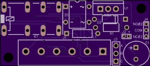
Well, the PCB blanks finally arrived. ![]() Here's the first "production" model.
Here's the first "production" model.
They operate on AC or DC, 12V or more.

Since there really wasn't room to put legends on top, I annotated the connections and jumpers on the bottom. Note the secondary set of relay contacts that can be connected on the left.

The units are built on 2 x 4 panels, 8 units for a panel. The first panel shown completed.

Attachments
Images (3)


Add Reply
Sign In To Reply
