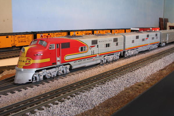
I have lusted after Laidoffsick's Santa FE E6 so I ordered a used AA Milwauke legacy E6 set and found new ATSF shells. The shells have come in and I'm going to detail the locos like I did the ATSF Alco PAs. Here are the shells, they are gorgeous. The donor locos are not in yet.

I'll be doing this while working on the Carbondale.

ATSF E6-1

ATSF e6-2

Attachments

Images (2)
  • ATSF E6-1
  • ATSF e6-2
Last edited by Ron H
Original Post

Replies sorted oldest to newest

Laidoffsick posted:

So you'll have them done by the weekend?

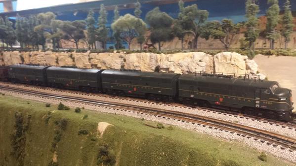
Man, I really wish that were doable. I'm going to take my time. I even got Blumberg's patent drawings for these trucks, but it looks as though lionel did an excellent job. I'll probably add sander lines and that is about it.

Did you try lowering the A unit and if so how?

Ron

I did not lower them. Looking at my A unit, the front sits higher than the rear and I'm not sure why. I never really considered lowering it back when I fixed the pilot, but I at least need to make it level. 

I had to lower the Legacy B dummy unit just to get it to match the powered A, and it does now. The B unit won't go any lower than I have it now because its a different design than the E6. So if I lower the A, it won't match the B. 

I'm curious if your AA set sits the same as mine because the powered and dummy are the same..... quite a bit higher in the front. I really notice the bigger gap between the shell and the trucks in the front.

Last edited by Laidoffsick

J daddy, not sure yet how I am gonna do this.

Usually build my own drawbars between units and have a lot of spare diaphragms around to use.  I am gonna sell the shells intact. I would use brass tubing to replace stacks.

Check out the posts from Norm and Central Fan on their sharks and my super detail Alco PA posts for some ideas. If you do not have fairly broad curves it might not be effective anyway.

Ron

yes, the dreaded brass tubing...

I did use dummy weaver couplers with great success on Lionel F and PA units. I replace only the dummy side coupler and leave the electro coupler on the other side. But the E6 I am going to rethink it, what diaphragms are you using?

20160818_213833

20160817_223651 - Copy20160817_214806

The last picture is the before pic.

I have been able to run on O72 curves with no issue.

but most of my layout is 0100.


Attachments

Images (3)
  • 20160818_213833
  • 20160817_223651 - Copy
  • 20160817_214806

You can see the stance I referred to here. The front of the A unit sits a lot higher than the rear for some reason.

28

I still need to body mount the front step. When I do that, I'll take a look and see why the front sits so high. If I could drop it low enough, I wouldn't need the spacer between the pilot and shell.... but then it wouldn't match the B unit, and that is already bottomed out as low as it will go. I already trimmed the skirts to clear the side frames as it is.  
29

The B unit I bought had broken 3 rail couplers and missing diaphragms so I used a folder paper one from Keil-Line in between the A & B to allow tighter curves while coupled so close. Plus they take paint well, unlike the rubber ones I was going to use. 072 and cross overs are no issue for these.

303132

Attachments

Images (5)
  • 28
  • 29
  • 30
  • 31
  • 32

J Daddy,

I suggest you follow Laidoffsick's example on the diaphragms.  I have the shell off the power unit and I'm trying to figure out how to disconnect the power trucks. The height of the frame over the trucks is determined by two diecast flanges on the truck. Trim them and I can lower everything.

I guess I'll have to pull the dummy apart to figure this out.

OK, the trucks are coming off and I wanted to show how detailed the side frames really are. They are weathered so the detail comes out. Ater I paint them ATSF silver, they will be weathered to pick out the detail again.

Also with the truck removed one can see the limiting flanges I mentioned. Going to grind these about 3/32 to start.

Sfrm 1s frm 2truck flange

Attachments

Images (3)
  • Sfrm 1
  • s frm 2
  • truck flange
Last edited by Ron H
Laidoffsick posted:

Yeah that's an entirely different frame setup from the Legacy E7s. Might be an easy lowering job for sure.

We'll see Doug. Hope so. Also, my powered A unit chassis is really bowed upward making the tail ride low. that may be the problem. I'm gonna brace my chassis with brass square tubing where I can.

Last edited by Ron H
Laidoffsick posted:

The lead unit comes with the closed door pilot. I bought another one from Lionel parts dept

The spacer was fabricated from styrene sheet, either .100 or .125. The pilot doesn't match the contour of the body exactly so you have to pick your alignment spots.

Thanks I was getting confused with the Burlington E5 I was working on... it has the monster claw coming through the pilot...

20150425_195038

Attachments

Images (1)
  • 20150425_195038
J Daddy posted:
Laidoffsick posted:

The lead unit comes with the closed door pilot. I bought another one from Lionel parts dept

The spacer was fabricated from styrene sheet, either .100 or .125. The pilot doesn't match the contour of the body exactly so you have to pick your alignment spots.

Thanks I was getting confused with the Burlington E5 I was working on... it has the monster claw coming through the pilot...

That doesn't look like a Burlington E5A, i.e. no fluted stainless steel sides. Looks more like an E3A/E6A painted silver.

Today working on the dummy A pilot. First one has to trim the pilot and if you wish, adding kadee coupler.

pilot 1Cut the pilot as shown.

pilot 2I had to grind the flange off the kadee cover plate then mounted  through existing cutout. Also the mounting for the lobster claw on the front truck will have to be ground back for clearance.pilot 3

Attachments

Images (3)
  • pilot 1
  • pilot 2
  • pilot 3

bending pilot 2Finishing the pilot. As Laidoffsick showed, the pilot is a little under radius at the ends to mate with the shell. He made a spacer and blended it to the shell and pilot.

I decided to try something different. I sliced into the back of the pilot thinking I could spread it the approx. 1/16 th or so required for each side and it worked.

Be very careful doing this as the castings are brittle and one can snap them.


Attachments

Images (1)
  • bending pilot 2
Last edited by Ron H
Laidoffsick posted:

Is the shell now low enough to mount the pilot directly or will you still need a spacer?

Hi Doug,

It is low enough that the pilot sits at prototype height. However, I realized the neat pilot mounting of the kadee is not going to work, as a long train will surely pull the pilot off. Soooo, I'll have to frame mount the Kadee. Another darn step.

Ron

Add Reply

Post

OGR Publishing, Inc., 1310 Eastside Centre Ct, Suite 6, Mountain Home, AR 72653
800-980-OGRR (6477)
www.ogaugerr.com

×
×
×
×
Link copied to your clipboard.
×
×