
PS PIC 2

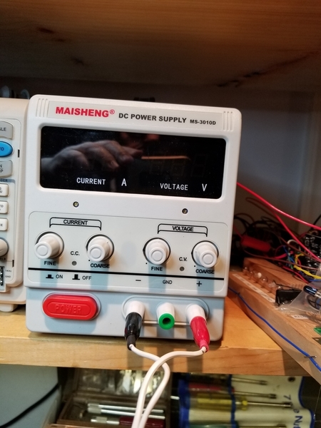
A number of topics on the forum have talked about the above readily available power supplies. They are nicely laid out, fairly compact and quite affordable; available in 5 amp or 10 amp versions. They are offered by several sellers on ebay and Amazon amongst others. They are both voltage or current controlled, and have a built in voltmeter and ammeter. Also they are fan cooled. As handy as they are, they all have one major drawback that can bite you hard if you don't follow the proper startup procedure. And that is if you inadvertently hookup the load first, then turn it on; POOF, its shot. (Don't ask me how I know this. ) The manual has this prophetic statement (if you read manuals) on page 1: "Do not connect any load to the power supply before it's turned on", followed by "Likewise make sure to disconnect the load before shutting down the power supply." All well and good as long as you read the manual and you happen to remember this.

In January I bought a 10 amp one (replacement for my first one!) and got to thinking about a fail safe method to prevent disaster. I collaborated with my good friend rtr12 (Tom) who has experience from his working career with latching relays. After a few discussions we came up with the following circuit:

Interlock Relay Circuit

The idea is that even when you physically connect the load to the PS, it won't be powered up until you turn the power on (which also powers up the wallwart relay power source), then push the NO Connect pushbutton. This energizes the relay. The first set of contacts closes to "latch" the relay on, and the second set puts power to the load. The relay remains energized until you push the NC Disconnect pushbutton, or there is a loss of power. Then the relay opens, disconnecting the load.

A second advantage is that if you experience a power blip while using the PS, the relay immediately opens, and when the power is restored there is no connected load (and no "POOF"). I have also found it very handy to be able to connect and disconnect power to the load using the pushbuttons instead of inserting and removing banana plugs. But that's just me.

It's easy to build using mostly parts in your surplus bins. You need a 12vdc DPDT relay good for 10 amps (if a 5 amp PS) or 15 amps for the 10 amp version. You need a surplus 12vdc wallwart (any output of 200 ma or more), and either two ON-(ON) pushbuttons, or one each of NO and NC.

As seen below I have hot glued the main components to a small chunk of mapboard, and pre-wired most of it. Most any standard DPDT 12vdc relay will work. I chose this one simply because I have several on hand doing nothing, and it has contacts rated at 15 amps. ( I think I bought them from Dale Holzman a number of years back)

Build 2

Here I have connected the wallwart power wires to the inlet power receptacle and the power switch such that the wallwart is powered with the main switch. Note the near orange elipses. Also note the red power wires connected in the far orange elipse. I chose to unsolder the original red wire from the outlet connection board, and splice it to the wire to the relay. Then the other wire from the relay is soldered to the original outlet board connection. Simple!

Build 3a

This view shows the map board hot glued in place and the pushbutton switches installed in the top of the cover (orange).

Build 4a

This view is the finished top cover with the new switches marked according to function. I chose to mount the switches on top because there is not much open space anywhere on the front panel of the PS. This location has turned out to be very handy and not in the way of anything else.

Build 7

And so the acid test. Like a charm she works! Here we are powering two auto type headlamp bulbs that pull about 4.5 amps each at 14.2vdc (lamps are not in the picture). The max current I was able to pull was 9.89 on the ammeter. Not bad; close enough to 10 amps for me. The fan was moving lots of air meanwhile.

Load Test 2

That's about it. Any questions or comments; shoot. It's a fairly simple 2 or 3 hour project once you have the parts rounded up. Since all the parts I used came from my spare parts bins, there was no real out-of-pocket expense involved. YMMV. I am loads happier using this little guy now. And more confident that I won't fritze it!  I really need to offer my thanks to rtr12 for all his help and expertise on wiring the relay to work for this purpose. Thanks Tom!

Rod


Attachments

Images (7)
  • Interlock Relay Circuit
  • PS PIC 2
  • Build 2
  • Build 3a
  • Build 4a
  • Build 7
  • Load Test 2
Original Post

Replies sorted oldest to newest

gunrunnerjohn posted:

One interesting twist on this power supply mod would be to just add a delay relay to the output pins, say a one second delay after power is turned on.  This would make it automatic and no extra button pushing required.

I haven't noticed any power blip on these when turning off, but it certainly has one when turning on.

The delay relay sounds like a good suggestion John, I hadn't thought of that. But I kind of like the idea of manually connecting and disconnection the load, so I am happy with way it is now. I guess you could also use a conventional latching style relay in place of this setup. I think I have a couple of P&B latching relays kicking around somewhere, but I think they are 120vac types. Using one of them would eliminate the need for the wallwart though, but then you are switching 120 vac with the pushbuttons. I think the way I have done it is likely safer.

The kind of blip I was referring to would be a power interruption external to the PS, the kind of momentary flicker that you get during a thunderstorm for instance. Hopefully the relay would drop out and prevent the PS from powering up again with the load connected.

BTW, does anyone know what component typically toasts when these switching type PS's go on the blink? I kind of vaguely recall that being discussed in a similar thread back a year or two ago. It might be simple enough to source and replace the component if you knew what to look for, but I have no idea where you would scare up a schematic for these things.

Also I should mention another alternative that rtr12 suggested was moving the NC Disconnect pushbutton to just ahead of the Connect pushbutton, in the wire to the actuation coil. This was apparently another way that they did these things back during his working career.

Rod

Last edited by Rod Stewart

I hung a scope on my P/S, mine is the typical 10A 30V model, probably identical to yours. The startup spike is scary, so that needs to be addressed.  The shutdown doesn't really pose a problem, at least with a sample of one.  That being the case, I decided to address the startup issue.  Also, the relay drops out pretty quickly, and it appears it's turned off before the power supply caps discharge and let it drop out of regulation.

I looked around the shop and discovered I had all the raw materials in hand.  On top is a mini 120V to 12V isolated power supply.  On the bottom is a 0-10 second delay turn-on module.  Looks right!

Power Supply Delay Mod Raw Materials

I didn't bother with a diagram as this was dirt simple.  I connected the 120V power primary after the power switch, and connected it's 12VDC output to the VCC of the timer module, observing polarity of course.  Then the timer module was simply inserted into the positive lead of the power supply going to the binding posts using the COMMON and N/O contacts. The timer was set for about a 2 second delay, that was after the power had stabilized at any voltage output setting.

In order to be safe here, I shrink-wrapped the 120V power supply in clear plastic, then it was stuck on top of the power switch.  The timer module is stuck to the case with the same Double-Sided foam tape.

Power Supply Delay Mod Installation

Attachments

Images (2)
  • Power Supply Delay Mod Raw Materials
  • Power Supply Delay Mod Installation
Last edited by gunrunnerjohn

Cam, they're the cheap Chinese spread.  I certainly agree they "shouldn't" have such behavior, but they do.  For $30, I can overlook that for a 300W max supply.  Now with a time delay on the startup, I'm good with my cheap supply.  I have an HP supply on the other end of the bench, but it doesn't have nearly the capacity of this one, and I'm sure it cost a WHOLE bunch more when it was new.  

There's a whole host of these, very similar design, but different interior layouts.  I'm sure if you checked the schematic, they're all basically the same design.  Mine is the well known MAISHENG brand.

Attachments

Images (1)
  • mceclip1

I found these supply online with different branding.  So I decided to see if Big Clive had a review.  He had two videos.  One was about a unit his friend had the caught fire - see photo.  As he is wont to do, he ordered one for review.  He shows some interesting problems with the UK style plug and power cable.  But you may be interested in what he had to say in general and his surmise on the cause of the fire.

Big Clive Power Supply Review

He did not mention the power up problem but I watched video by another user demonstrating operation of the supply, in particular the constant current feature.  I am used to a constant voltage supply with a variable current limit.  You set the voltage, then short the supply to set the maximum current.  If the current exceeds the limit the supply folds back the voltage to reduce the current.

However, apparently these supplies in constant current mode will INCREASE the voltage to try to achieve that current setting.  There are some cases where this would be useful but usually you want a voltage supply where you can limit the max current if something goes awry.

It strikes me this feature is muddled during power up and may be the cause of the switch on glitch.

Smoking PS


Attachments

Images (1)
  • Smoking PS

Cam, when I worked in industry, especially the 20 years in aerospace, we had pretty much the cream of the crop as far as bench test equipment.  However, I'm back in the real world where I don't have unlimited funds.

Overall, I haven't seen the issues described in your video, and I've used both the CV and CC at varying times.  As far as his issue with the power cord, I use the US cord, and it looks like a bog standard cord.

I had to take the panel out to get my mods in, and I made sure the screws and lockwashers were secure.  As for the test leads, I threw those away, I solder my wire into the banana plugs, problem solved.

This is not a laboratory quality power supply, but it works just fine for what I do with it.

Rod Stewart posted:
 
The manual has this prophetic statement... "Likewise make sure to disconnect the load before shutting down the power supply."  
gunrunnerjohn posted:
 

...Also, the relay drops out pretty quickly, and it appears it's turned off before the power supply caps discharge and let it drop out of regulation.

Rod, is the reason to disconnect the load before shutting down because it might put out some anomaly greater than the set-regulation voltage?  What if you lose AC power for whatever reason during operation - like the cat or dog pulls the plug out of the wall socket?

I wonder if the voltage on the power supply caps is really the issue.  What is causing the apparent output voltage anomaly on turn on?  That is, does the power supply really enable voltage output before the power supply caps are fully charged?  I like the relay drop out before the power supply caps discharging...but wonder if it's fast enough!

In any case, I like GRJ's delay-on relay concept...but with possible "tuning" to speed up the relay drop-out time (e.g., reduce capacitance on the step-down, or place a resistance across the relay coil current). 


I did indeed Rod, I never saw excessive voltage, but I did see a what appears to be a contact bounce several times.  The voltage would come up, then drop to zero for about 100 microseconds, then back at the set voltage.

I also checked the shutdown, which is why I decided to leave it the way it was.  I ran it at a number of voltages and with and without a load.  I never saw any overshoot, just a shutdown.  FWIW, the shutdown was instant, so I'm sure it was the relay on the timer dropping out before the power supply dropped out.  I know when you shut it down, the voltage tails off without the relay in the picture.

Bottom line is I never saw any voltage overshoot, so I'm pretty happy with my solution.  I didn't like the fact that I saw a little contact bounce, but I guess that's what you get for a buck on eBay.

Stan, I suspect there is no enable function, from the looks of the turn-on of the stock power supply, I suspect they just fire up the circuit and it stabilizes once it gets running.  The overshoot is about 2x the set voltage at times.  Of course, I can't check it without taking it apart now, as my relay prevents me from seeing the startup.

Another point, it appears the startup spike is greater at lower set voltages, I got almost nothing at settings of 25 or 30 volts.

So today I checked the modified 10 amp PS using the connect/disconnect pushbuttons, with my scope hooked up.

I tried several different loads and settings and various scope settings, but did not see any kind of spike, point bounce, or anything else suspicious.

If the PS does have a spike at startup it certainly was not evident, because of course there is no output until you push the connect button, which is always after initial power on. So I am happy that it’s pretty much as safe as it can be. All good.

I may run some similar testing on my Riden unit as well, just for fun.

Rod

John, I did try to observe any anomalies using the disconnect button to open the load relay. Nothing, just a straight line drop to zero volts as expected. There may very well be odd stuff happening upstream of the relay, but I did not open the PS up to check. Bottom line; the relay is doing its job and protecting the load from any strange spikes or weird stuff. And it's protecting against starting the PS up under load. So I am happy with it.

Stan, I have not actually tested a power interruption event, or momentary power blip, to see if the relay drops out fast enough to protect the load . May have to check that out. Originally I was thinking of adding a 100-220uf or so cap across the relay coil connections, but I did not want to slow down relay opening at all in the event of power loss.

Another thing, I added right across the output terminals a 36V TVS, just like those used on the layout. The manual mentions the importance of disconnecting an inductive load before turning the PS off, likely to mitigate any back EMF kick that might damage the PS electronics. So I figured a TVS should take care of that sort of an event regardless.

Another interesting item in these PS's is shown below:

PS PIC 8a

The circled iron ring encircles the main + and gnd wires from the main board to the output terminals on the front of the PS. I note in John's pics that his has the same item installed. I figured this might be some kind of choke to perhaps kill output spikes on startup or shutdown. What do you guys think?

Rod

Attachments

Images (1)
  • PS PIC 8a

Since both the + and - outputs go thru that donut, this would not suppress a differential spike since both wires are treated "equally".  This is no doubt a common-mode noise filter which rejects high-frequency (e.g., radio) noise; I wouldn't be surprised if it was a last-minute add-in so that it just barely meets some emissions certification to allow shipment into the US, Europe, etc. 

Add Reply

Post

OGR Publishing, Inc., 1310 Eastside Centre Ct, Suite 6, Mountain Home, AR 72653
800-980-OGRR (6477)
www.ogaugerr.com

×
×
×
×
Link copied to your clipboard.
×
×