Hi Stan,


The module I purchased was the:


"Square Wave generator NE555 Duty Cycle and Frequency Adjustable Module".


I cannot find an oscillator module on ebay (maybe my search nomenclature is incorrect), that uses the 555 chip---and by the way, the module you show in your picture says it is an NE555 oscillator module. Only the NE555 chip is used in the oscillator modules listed at this time on ebay.


But I didn't think about connecting the LEDs in series. For my use, I just want to drive several crossing flashers, so I think I need to use individual modules (but I haven't sat down to think it through).


Thanks for the response and great explanation.


Ken

Ken,


I should have made clear that 555 and NE555 can be used inter-changeably.  They are the same part.  I looked at your module listing and saw the comment about 35mA output capability.  It's puzzling.  The module uses the 555 chip and from what I can tell there is nothing on the module that limits the 555 from operating at its full current driving capability which is over 100mA.  Well, it appears to use a small LED that might be tied to the output but this should not consume that much of the available current.


Not that you would know or think to look, but one reason the 555 IC is still used by the billions even today is because of its high output current capability.  100mA is high current for a chip like this. 


ne555 stm datasheet

Attachments

Images (1)
  • ne555 stm datasheet
Last edited by stan2004

Dear Stan


I finally built the circuit and thank for the instructions. I am a little confused when it comes to where I connect the  two IR to the relay.


I hooked the IR through the diode, the cap and to-92 to the relay as pictures about diagram and nothing. The red light on the IR light up but no relay action. I did find an older IR diagram of yours that show a different hook just using one IR.


Last edited by nvocc5
Originally Posted by nvocc5:

I finally built the circuit and thank for the instructions. I am a little confused when it comes to where I connect the  two IR to the relay.


I hooked the IR through the diode, the cap and to-92 to the relay as pictures about diagram and nothing. The red light on the IR light up but no relay action. I did find an older IR diagram of yours that show a different hook just using one IR.


Kris, I'm not sure which exactly which circuit you're trying to build.  The above only shows a 10K resistor, followed by a NPN transistor (in a to-92 case), followed by a relay module.  So I don't understand the reference to the diode and the cap???


Originally Posted by nvocc5:

Here is the older diagram for hook up of one IR. Sorry I could get the picture load up to the thread.


https://ogrforum.ogaugerr.com/t...79#41271601014521679


Here's the photo from the above link.  I assume it uploaded properly assuming you meant you could not get it to upload.  Is this the one you're referring to?  Again, I'm not clear on exactly what parts you have and which circuit you're trying to build??? 


ogr%20IR%20reflective%20and%205v%20spdt%20relay%20module

Attachments

Images (1)
  • ogr%20IR%20reflective%20and%205v%20spdt%20relay%20module

Hi Stan


Here is the circuit I am trying to build. I a little confused on how to hook up the IR to relay. I have the TO-92 E to relay GND and C to relay IN. That all that I have hooked up to the relay.  What am I missing? Everything before the TO-92 is hooked up as per the diagram. The IR led had small led on it's side and they lite up red. Any help you can provide I would be grateful.


ogr IR module itad with delay hookup 5v

Originally Posted by nvocc5:

I a little confused on how to hook up the IR to relay. I have the TO-92 E to relay GND and C to relay IN. That all that I have hooked up to the relay.  What am I missing? 

Hi Kris, see if this helps:


ogr%20IR%20module%20itad%20with%20delay%20hookup%205v

There should be 3 connections between the circuit on the left and the 5V relay module.  Also, the 2-pin jumper must be installed on the 5V relay module.


Maybe you made a typo but the TO-92 connections should be:


C to relay VCC

E to relay IN


And the 3rd connection is from the common or "-" of the IR circuit to the GND of the


relay module.

Attachments

Images (1)
  • ogr%20IR%20module%20itad%20with%20delay%20hookup%205v

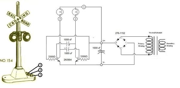
Stan (or John), (or anyone else), some time ago you posted a neat circuit for flashing 2 LEDs. I put it together and it works great (with the 555 Oscillator module). I think at that time you also mentioned that the circuit would not work with the standard Lionel crossing flasher. Having gotten into this, I understand. Since both lamp sockets are physically tied to the frame (ground) and since they can't be removed, your circuit approach isn't doable.


Does anyone have a suggestion or a work-around because an electronic flasher is much better than the Lionel contactor.


Ken

Last edited by ken's trains

Stan, I apologize. I went back to your old posts on the above topic. If I understand correctly, the circuit that will work with those flashers is the one that has the Oscillator module cycle the Relay module. I guess, using that circuit, I could skip the LED swap and just apply 12-16 VAC to the common terminal of the relay and power the incandescent lamps.


Am I correct in the above.


Ken 

Dear Ken


I have reach the same point as you in this project. I have it on hold right now because of life's other demands. I am considering changing the light bulbs to led for this project. I not a fan of drilling out the rivet that hold the light bulbs in place and using  Dept 56 Village Tacky Wax to hold the leds in place. But if anyone else a better idea I am also listening.

Originally Posted by ken's trains:

Stan, I apologize. I went back to your old posts on the above topic. If I understand correctly, the circuit that will work with those flashers is the one that has the Oscillator module cycle the Relay module. I guess, using that circuit, I could skip the LED swap and just apply 12-16 VAC to the common terminal of the relay and power the incandescent lamps.


Am I correct in the above.

Hi Ken, you are correct in principle. That is, a relay could be used to switch AC back and forth between the two incandescent bulbs.  The practical problem is an SPDT relay always has one or the other contact "on".  So in the simplest implementation of the oscillator module driving a relay module, one crossing lamp would be solid ON when idle.  Then when the oscillator module is activated only then the lamps would alternate flash.  Clearly this is not what you'd want! 


If you want to switch 12-16VAC to your crossing lamps I'd say the simplest solution is to add a second 99 cent relay module.  This second relay module would turn on when the oscillator module turns on - and would apply your AC voltage to the 1st relay module's common.  Hopefully this makes sense; if not I will sketch out a diagram for you.


As an aside, I was looking back in this thread and see a posting about using a relay module to drive DC voltage to alternating lamps.  In this case (from March 17) the DC voltage was 5V but could be 12V if using a 12V relay module; the oscillator module should function just fine at 12V.
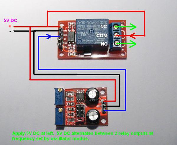
 

ogr%20ne555%20drives%20relay from 3-19-2015%20module

In this special case the same DC voltage which powers the oscillator module is switched thru the relay module.  So if your lamps can be driven at 5V (or 12V) DC, then this configuration might apply.  BUT note the surrounding thread discussions in that timeframe.  In this particular case with your crossing gate frame tied to AC common, this assumes the "-" side of the DC circuitry is the same.  As discussed in the thread this may or may not be the case depending on where your regulated DC voltage comes from.  If you want to pursue this approach - or just want to hash it out - we can do that too.

Attachments

Images (1)
  • ogr%20ne555%20drives%20relay from 3-19-2015%20module
Last edited by stan2004
Originally Posted by nvocc5:

..I am considering changing the light bulbs to led for this project. I not a fan of drilling out the rivet that hold the light bulbs in place and using  Dept 56 Village Tacky Wax to hold the leds in place. But if anyone else a better idea I am also listening.

So no one sells a drop-in replacement LED bulb that plugs in to the incandescent socket?


I don't know what the bulb looks like for a Lionel gate but as crazy as it sounds I've made my own LED replacements by carefully breaking the glass and cleaning out the filament from a burned out bulb.  In other words I'm making a mating plug to your socket which is apparently hard to remove. 

Thank you John.


Dear Stan


I did not think of that of getting screw in led bulbs, cool. For Marx and Lionel crossing lights would know the size bulbs and a good supplier for led replacements?


However, I do have a crossing gate that I would also place on the IR circuit to active it.


I also purchased AXIOM RELAY V23026A SPDT 5VDC PC MOUNT item#381441676844 to hook up the AC part of the circuit. I just have not figured out how to hook it up to the IR circuit.

Originally Posted by nvocc5:
I did not think of that of getting screw in led bulbs, cool. For Marx and Lionel crossing lights would know the size bulbs and a good supplier for led replacements?

You might try starting a separate thread asking if anyone makes a drop-in LED replacement bulb for your crossing lights.  I don't know what the bulbs look like and I was simply suggesting if you can't buy one you might be able to make one by recycling the base/plug of a burned-out bulb.

However, I do have a crossing gate that I would also place on the IR circuit to active it.


I also purchased AXIOM RELAY V23026A SPDT 5VDC PC MOUNT item#381441676844 to hook up the AC part of the circuit. I just have not figured out how to hook it up to the IR circuit.

Not sure exactly what you have and what the "loose" AXIOM 5V relay is for.  I don't know what you mean by "AC part of the circuit."

First, thank you John, I remember that circuit from many posts ago. I just need to fool around with the IR detection stuff and try to get it to operate some of the accessories.


Second, Stan, I just finished re-wiring my working configuration (worked with LEDs like in your diagram) for AC operation of the crossing signal. Before I turned on my PC, I was looking at one lamp lit all the time, as you predicted. So, I went through my parts bag and came up with a 2-ch relay module. I need to go back to the ebay listing to see how it works. It would eliminate the need for a second relay module.


Thank you all. If anyone knows how the 2-ch relay modules work, help would be appreciated.


Ken

Leave jumper in.  It jumps JD-VCC to VCC which are different signals. And you're saying you activate the relays by touching IN1 or IN2 to GND.


You should have a signal from the IR detector part of the circuit that provides 5V power when the IR detector is active.


This 5V should go to the 5V power of the oscillator module AND to the VCC on the 2-ch relay module.  GND on the relay module hooks to the ground of the IR circuit.  IN1 connects to GND.  IN2 connects to the output of the oscillator module.


So when 5V is applied to the combo of the oscillator and the relay module, relay 1 immediately turns ON (because IN1 is tied to GND).  Then relay 2 will click on and off since it is driven by the oscillator module.  Your AC source gets switched on by relay 1 and feeds relay 2 Common.  Relay 2's NO and NC outputs drive the alternating lamps. 


edit: diagram added


LionelsoniFlasher-1

Attachments

Images (1)
  • LionelsoniFlasher-1
Last edited by stan2004
Originally Posted by ken's trains:

This is the listing:


2-Channel 5V Relay Module With Optocoupler For Arduino DSP AVR PIC ARM


I have been fooling with it, and the only issue seems to be that the 2 triggers are ground and I can't figure out what the jumper does (currently jumps VCC to VCC.


Ken


Ken

Here is a schematic of the module showing the purpose of the jumper. It allows having separate power Vcc for the input and output sides of the circuit.

2ChannelRelayArduino

Attachments

Images (1)
  • 2ChannelRelayArduino

Well, if you have a 12V DC Wall-wart and hence can "safely" tie DC "-" to the metal crossing gate frame (terminal 1) then you might not need the 2nd relay after all.  If you can drive the bulbs with 12V DC this photo from February 2015 posting in this thread shows how you only need a single-relay module if the IR circuit supplies 12V DC (instead of 5V DC) when activated.


ogr%20corssing%20flasher%20lego%20style

Attachments

Images (1)
  • ogr%20corssing%20flasher%20lego%20style

Hi Stan,

After many new activities I am back.

First to the activities for any that may be interested:

1) My neighbor and good friend is a mechanical genius. He came up with a design for a new turntable to replace my very old one (which was a 22" dia. unit driven by a dc motor with a rubber drive turning a 24" wood disc. We tried to make it work by using a stepper motor with belt drive (instead of the original drive mechanism) controlled by an Arduino. This worked but didn't have the repeatability accuracy. So he came up with a totally new design using a lazy susan and slip ring combination, driven by a larger stepper motor with Arduino control. I will post details and code if any interest. Unfortunately, the motor mount was custom-made with his 3-D printer, but the total cost of parts was less than $100.

2) He then got more into the hobby when I explained my concern with the crossing gate and approach signals/accessories being energized for too long (burning up solenoids). So he completely designed and printed (3-D printer again) a crossing gate with flashing LEDs on the cross and gate, and operated with a tiny servo motor (no burn up). We both came up with an Arduino code version to operate the gate. I made a simple mock-up model of same and could post a video of the code in action. Took me long time to learn enough C language to write the program.

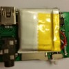
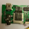
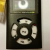
This brings me to the question (sorry if the above is of no interest or in the wrong area).  With the new gate design, we want to incorporate audio. Back many posts ago you presented your design using a modified MP3 player & audio amp. About a month ago, I bought the only cheap MP3 player available on ebay. Mine has a display and the circuit configuration is somewhat different than the one you modified. As such, I am posting pics of mine and would very much appreciated help in where to place the added capacitor. I will also check the audio amp I bought and see if it is same or different.

Thanks for any help.

Ken


Attachments

Images (4)
  • 20171009_215027
  • 20171009_215123
  • 20171009_215239
  • 20171009_215351
ken's trains posted:
...

This brings me to the question (sorry if the above is of no interest or in the wrong area).  With the new gate design, we want to incorporate audio. Back many posts ago you presented your design using a modified MP3 player & audio amp. About a month ago, I bought the only cheap MP3 player available on ebay. Mine has a display and the circuit configuration is somewhat different than the one you modified. As such, I am posting pics of mine and would very much appreciated help in where to place the added capacitor. I will also check the audio amp I bought and see if it is same or different...

I see hundreds of choices on eBay including the 99 cent free-shipping version I've used but pink - 10 cents more if you want a black case.    

99 cent mp3 player pink

Yours seems to be going for $1.79 free-shipping in black.  All this high-finance is pretty heady stuff!

mp3 player with screen

I've not messed with the screen version.  But I'm sure we can figure something out.

But first if I can make a suggestion, start a new Electrical thread titled MP3 sound for crossing gate or something like that.  I think the existing thread title about IR and optical sensors might not draw in some guys that have sound related expertise.  Some additional info to include would be:

1. Identification/photo of the amplifier module you have

2. Exactly what circuit/voltage or trigger drives the sound - 5V DC, 12V DC, Accessory 14V AC voltage from a relay, etc.

3. Did you mess with the unit before dis-assembling it?  Specifically, the way I use these modules is to turn the power switch "on" to confirm that it automatically starts playing an MP3 "song" with no additional button-pressing.  For all I know the screen based version wants to interrogate you requiring menu navigation.  So did you load a single MP3 "song" such as a crossing gate MP3 sound onto the microSD card, then turn on the player, and confirm the song automatically starts thru the audio jack via some earbud headphones?  The battery must have been charged which is usually done via a mini or micro USB cable.

Attachments

Images (2)
  • 99 cent mp3 player pink
  • mp3 player with screen

Hi Stan,

I have done as you suggested and moved this discussion to a new forum titled:

"MP3 Sound for Crossing Gate" as you had suggested. Also this is the audio amp module I purchased on ebay:

"DC 5V Mini Digital Amplifier Board Class D 2*3W USB Power PAM8403 Audio Module ".

See you at the other forum. I have done as you suggested and tried a few things.

Ken

HI all. Well after spending a year on 3D design and construction of a 24" turntable (TT), I need some more electrical help. I have posted the TT stuff under a different topic. Upon completion & installation of the TT, it became apparent that an engine could run into the TT pit when the TT track was not positioned with the entry track. Decided to use an across track optical sensor to detect engine near end of track and breaking beam would open relay controlling (isolated) track voltage. Long ago, Stan posted lots of circuits for configuring optical sensors. However, one of the diagrams showing how to connect an LED emitter/IR sensor combination to control a 5V relay does not work as shown. If I connect the (-) output of the sensor directly to the relay it does not trigger. If I put a 10K resistor on the (-) sensor output and connect to grd and then also connect the (-) sensor output to relay trigger, there is not enough current to fully trigger the relay. However, the sensor sensitivity is great. If I reduce the resistor value (had to come down to 500 ohms) to allow sufficient trigger current, the sensor sensitivity is terrible (need to be almost touching the emitter). Did not realize that was how sensor sensitivity was controlled. So, is the solution to use the sensor (with 10K limiting resistor) to trigger a transistor and use the transistor to trigger the relay??

If I am close, would really appreciate a circuit sketch showing values.

Ken

ken's trains posted:

...Long ago, Stan posted lots of circuits for configuring optical sensors. However, one of the diagrams showing how to connect an LED emitter/IR sensor combination to control a 5V relay does not work as shown...

So we're talking apples-apples I assume it's a diagram from this thread.  What's the date & time of the post with the diagram?

Hi Stan,

Well I'm really sorry, but it's been a lot longer than I remembered--tough to get old. A good date/time would be 4/9/15 & 10:22 PM (that was my re-post of your original design). As to my most recent questions, I have the single emitter/sensor combo working now--just followed your design of that time. But would still like to know if sensor sensitivity is controlled by current through the sensor--seems to be what I experienced. If that's the case, I guess that's why this only works with the transistor in the circuit and the sensor just providing a trigger for the transistor which provides sufficient current to trigger the relay?? [It seems that the only thing that should be happening is varying light intensities affecting how much the sensor turns on--not the opposite; but then I don't understand how phototransistors work].

Second question regarding your earlier (4 yrs ago) schematic: you have a resistor/capacitor combo in the circuit that provides a time delay. If I remove those 2 components and just connect the 1st 10k resistor to the transistor base (since I don't need a delay), will the circuit still work?

Lastly: I am using this setup across a section of track to prevent an engine from running off the end of the track into the turntable (TT) pit by shutting off power to that track when the beam is broken. However, I need to disable (or bypass) this function when the TT is aligned with the track (and no I can't easily monitor for TT/trk alignment--too few slipring wires available) to allow engine to enter TT. So, other than adding another relay to bypass the 'safety' function (controlled by a switch at the console), is there some way to modify your circuit to easily disable the 'beam break' from triggering the relay (with some command from the control console; an "Enable/Disable" switch)?

Again, thank you for all of your help, and I can't believe it's been 4 yrs. since I've been on this topic. Didn't realize the turntable design & construction had consumed so much time.

Ken

Last edited by ken's trains

Stan, it's me again. This was my (one of) main confusion. In your 8/12/15 at 5:47pm post, you show 2 sensors in series with the output of the 2nd connected directly to the control terminal of a 5VDC relay. I get the relay to trigger with one sensor connected this way, but the relay is energized when the beam is not broken. This is my normal condition and not acceptable. I tried changing the H/L trigger jumper on the relay, but that didn't work since I don't have a ground with the beam unbroken. I tried removing the capacitor, 2nd 10k resistor & diode (since I don't need a delay), but the relay will not trigger (tried all combos of H/L jumper). In one of your posts you had a push button that you crossed out and said "replaced with sensors in series". However you did not mention whether or not when removing the PB, the connection from Vcc to transistor base through the 10k resistor was still required. I have not connected that 2nd 10k resistor from Vcc to base--is that the problem.
Please clarify.
Ken

kens trains IR

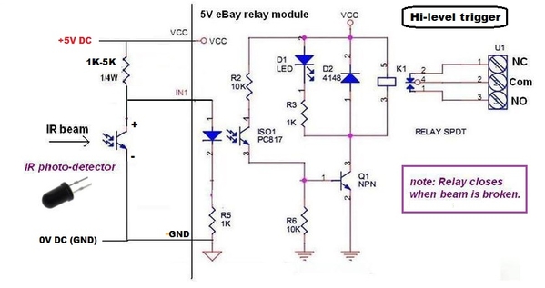
I realize that most eBay relay modules available now have a jumper(s) to select either H or L level trigger.  But let's just assume the H "only" module as described in the original discussion from years ago.  Since you don't need time-delay capability, as you correctly concluded, you don't need to worry about the capacitor/transistor circuitry.

Since you want the relay to turn ON when the beam is broken, try the above circuit.  Here's the steps in order.

- apply 5V DC power to the relay module 

- insert a 1K to 5K resistor between +5V DC and IN1 trigger.  The relay should turn on.  The resistor applies a HIGH trigger.  You want to insert the largest resistor value that reliably fires the relay.  So start with, say, 1K which will surely fire the relay.  If that works,try 2K or 2.2K (whatever you have).  If that still works, try 4.7K or 5.1K (whatever you have).

- insert the IR phototransistor.  When the phototransistor is illuminated, its resistance becomes a few hundred Ohms or so.  This shunts all the current from the IN1 trigger input to ground and the relay turns off.  If you break the IR beam to the phototransistor, the phototransistor's resistance jumps up to thousands or millions of Ohms which effectively means it is taken out of the circuit and the relay triggers as if the phototransistor is not there.


Attachments

Images (1)
  • kens trains IR
ken's trains posted:

...

Lastly: I am using this setup across a section of track to prevent an engine from running off the end of the track into the turntable (TT) pit by shutting off power to that track when the beam is broken. However, I need to disable (or bypass) this function when the TT is aligned with the track (and no I can't easily monitor for TT/trk alignment--too few slipring wires available) to allow engine to enter TT. So, other than adding another relay to bypass the 'safety' function (controlled by a switch at the console), is there some way to modify your circuit to easily disable the 'beam break' from triggering the relay (with some command from the control console; an "Enable/Disable" switch)?


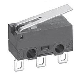
This reminds me of the "problem" of killing power to the approach tracks to either side of a lift-bridge.  The mechanism must remove track power if the bridge is up so your $1000 engine does not perform a swan-song dive into the abyss.  The most common method on OGR is to use a lever/hinge/leaf switch.  When the bridge lifts, the spring-loaded leaf pops out and power is removed to the last few feet of track before the bridge.

D2F_hinge_lever_DSL

So for a TT, I'd think something similar could be used.  For example, you could have one leaf switch per spur.  A tab/nib/finger on the rotating TT "bridge" would press the lever of the switch when it is aligned to the spur.  The switch then provides track-power continuity to the last few feet of track feeding the TT.

But given the topic is optical sensors, I suppose you could have a phototransistor on each spur "aimed" toward the center of the TT.  The TT "bridge" would have one IR LED firing an IR beam.  When the TT is aligned to a particular spur, it activates the phototransistor which triggers the $1 relay module.  The relay then provides track-power continuity to the last few feet of track feeding the TT.

Having just a single IR LED on the rotating TT section should not require adding more slip-ring circuits.  That is, you could use AC track power to power the IR LED.  Simply rectify the AC to DC and use a resistor to limit the current to the IR LED.

Attachments

Images (1)
  • D2F_hinge_lever_DSL

Add Reply

Post

OGR Publishing, Inc., 1310 Eastside Centre Ct, Suite 6, Mountain Home, AR 72653
800-980-OGRR (6477)
www.ogaugerr.com

×
×
×
×
Link copied to your clipboard.
×
×