
I've read where DCC is high frequency AC that carries the digital control signal to the decoders in loco's etc. the decoders recieve the signal and convert the AC to DC which powers the motor etc. the digital signal controls the amount of DC to the motor, controls the whistle, horn, etc., but according to NMRA "The DCC signal is an alternating DC waveform, which contains the digital information, This coded signal controls a specific decoder placed in a specific locomotive causing it to use as much of the track voltage as it needs to move forward or backward, turn its headlight on or off or even dim it for meets with other trains on another track.  So which is it AC or DC based?  I use a RRampmeter to measure DCC volts and amps (also for AC and DC), but am picking up conflicting signals (pun intended) in terms of the basis for DCC - is it AC or DC?  Thanks.

Original Post

Replies sorted oldest to newest

DCC being A/C or DC is like the great engines vs. motors debate, e.g. what defines and engine and what defines a motor .   In the case of DCC, both sides have a valid argument.  The signal crosses zero volts so it is alternating (A/C); however, at its heart, it is a bi-polar D/C signal, so it could be considered an alternating DC waveform.  It all comes down to which side of the tracks you come from .

Scott Kay 

I come from the engineering side, so it's AC.  It's really very similar to frequency modulated radio signals, they also have a variable frequency with the data encoded as frequency variations.  Just like any other AC, the net DC voltage on the rails with DCC is zero volts.  FWIW, a true RMS meter will measure DCC voltage as long as it has sufficient frequency response.

Time to put on my Nomex suit for the incoming flames.

Attachments

Images (1)
  • mceclip1
gunrunnerjohn posted:

I come from the engineering side, so it's AC.  It's really very similar to frequency modulated radio signals, they also have a variable frequency with the data encoded as frequency variations.  Just like any other AC, the net DC voltage on the rails with DCC is zero volts.  FWIW, a true RMS meter will measure DCC voltage as long as it has sufficient frequency response.

Time to put on my Nomex suit for the incoming flames.

Now thats funny..i would like to borrow that phrase if i may...its either your phrase or "Foam down the runways"


Doug-Sr posted:

help me with my missing education i have a digitrax 150 that uses a ac power pack also a a zepher 51 that uses only a dc power and they both can be uses together that does confuse me

I think he is referring to these 2 units use either AC or DC as INPUT to the Digitrax command stations.

Some DCC systems will only accept AC input, some will accept AC or DC as a power source. It's a little simpler to make them AC only input. In my experience DC input is superior, because you can use a regulated DC supply. Finding a regulated AC supply is pretty much impossible for us. (they do exist).


There was an option, now fallen into disfavor, on some DCC systems to modify the DCC output to the rails to allow a DC only loco to run, and that was indeed called "zero stretching", basically "stretching" one "half" of the AC signal, so there was a lot more time on the positive part of the "AC cycle", so it was a long pulse of positive voltage, and then a short pulse of negative... so it was MOSTLY DC... still make motors buzz and heat up.

(DCC modifies the AC square wave "timing" to give the digital signal, so modifying the signal to a gross level, i.e. "stretching" a "zero" made it this "mostly" positive DC pulse with a little bitty "negative pulse". Picture below shows "normal" 1's and 0's

Picture below shows an example of zero stretching in the middle of a normal DCC sequence.

Hope that helps a bit.

Greg


I just wrote a paper and posted it at the Digitrax-Users group site all about various test equipment you might use to measure the DC signal (and also why what somebody is using might not be working).  Things from light bulbs to multimeters to oscilloscopes.  In doing that and poking around online, I found confusion all over the place with some arguing mightily that it is NOT an AC voltage.  Even a DCCwiki claiming that.

I think some of the confusion is that typically the DCC voltage is created from only positive voltages so people think no "negative" can exist.  But the NMRA does not force you to make the waveform in any particular manner.  They do "recommend" that there be a "common", but it is not required.  And of course, neither track rail is perpetually a "common".

The typical way is for one half cycle to hold one rail at a positive voltage and the other to "common".  And then on the other half cycle hold the other rail at a positive voltage and the first rail to "common".  So, you have two positive pulsating DC voltages that are the inverse of each other.  Some think no negative voltage can come from this.  But the voltage of interest is BETWEEN the rails and whether a voltage is positive or negative depends on your point of reference.  When one rail is positive, the other is negative relative to it.  The voltage BETWEEN the rails is most definitely AC.  There are other ways we know this.  We can connect a scope and see positive and negative half cycles with no DC offset.  We need bridge rectifiers in decoders to convert to real DC.  If we put a multimeter set to DC across the rails we read zero (or very close to it).

Also, you could certainly generate the voltage differently such as taking a positive and negative supply and, by a switching means, swap those voltages between the rails.  Or you could use only negative voltages instead of positive ones.  The result would be the identical AC waveform the decoder would not know the difference.

Another confusion is if the DCC voltage has "polarity".  Being an AC voltage, by definition, it does not have a polarity.  It has a phase.  NMRA correctly uses the term "phase" in various places in the standards and technical notes.  So that much is good.

But most purveyors of things like auto reversers say "polarity".  This may be because people understand "polarity" better than "phase".  Or it harks back to the thinking of DC power pack control.  Digitrax says "polarity" in a data sheet, but in a technical note says, "...phase (or polarity if you will.)".  Like somebody who knew electronics jargon wrote the technical note, but had to tolerate the misnomer.  I'm pretty sure that any electrical engineer would feel "polarity" does not apply to AC other than in describing waveform crests or that the "polarity is constantly changing".

But I think the NMRA muddies the water some with some other terminology they have.

Such as "Bipolar DC".  I suppose this isn't technically wrong and it is used elsewhere in the world (only because it is square wave).  But "Bipolar" is another way of saying "AC".  And all AC is "bipolar".  Unfortunately, some note this as "proof" the waveform is "DC".

And the NMRA really makes things muddy with their term, "DCC Positive Polarity" which is “The wire or rail which has a positive voltage for the first half-cycle of the DCC bit”.  They are trying to define a rail (Rail "A" as opposed to Rail "B") in a sense of phase.

NMRA also uses the term "Digital Signal".  Again, not technically wrong if viewed broadly.  But in electronics a "Digital Signal" is typically voltage LEVELS such as 0 VDC being a "0" and +5 VDC being a "1".  Of course, besides voltage levels other than +5 (or even zero and a negative voltage) there are all manner of such encoding such as using zero and a positive and a negative voltage "duobinary" signal.  But it is always in terms of voltage levels.

Instead, the DCC AC voltage is modulated and might more correctly be called a carrier with data "transmission".

And the type of transmission is Frequency Shift Keying (FSK)  I see an example of that in a previous comment that is typical for radio (or radar) where some number of cycles of a frequency denote the state and have to be demodulated with fairly fancy electronics.  The DCC voltage can be handled easier by just timing zero crossings (and the NMRA uses that "zero crossings" term which is another BIG clue that it must be an AC waveform.)  Nothing about the concept of FSK says a "0" or "1" need be X number of cycles, so long as it is one cycle, that's enough.  And that's DCC.

A Lenz patent (the mother of the NMRA concept) even says, "...square wave voltage signal which is frequency and/or pulse width modulated”.  Lenz, being in the electronics design business, would certainly know.  Mentioning "pulse width modulated" is just to make the patent broader.  PWM is not used.  FSK is.  Although you see in blogs and elsewhere people saying the DCC signal is PWM which it is not because the duty cycle never varies.  The Lenz patent also says you could certainly use a sinusoidal wave, but essentially says why would anyone want to bother.

Being a square wave is 1) easier to create and 2) contains more power for a given voltage.  Otherwise, it is no less "AC" than the voltage at your electrical outlets.

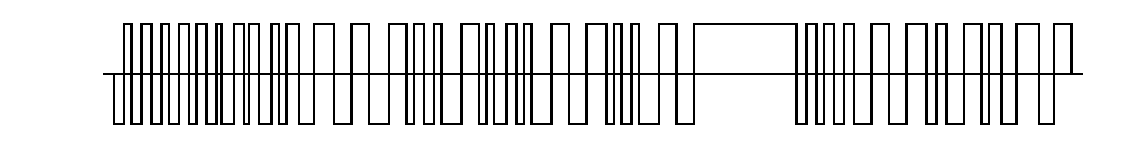
And then there is the pesky "zero bit stretching" which was mentioned a little in a comment above.  This is NOT required by the NMRA and seems to have been accommodated (allowed) to soothe people concerned they couldn't run a DC locomotive.  Not every manufacturer supports it.  To explain it in a bit more detail (and what it means to the AC versus DC argument) is that either half cycle of the "0" bit can have a longer than normal duration.  Using the NMRA terminology for Rail A being when the first half cycle is positive, if you hooked up a scope with the probe on Rail A and ground clip on Rail B, you see the first half cycle of the "0" bits stretch longer and longer for more and more throttle forward.  And the negative half cycle of the "0" bits stretch longer for reverse throttle. (Using address 0000).  Not just some zero bit, but all the zero bits are affected.

"Zero bit stretching" does introduce a DC component to the waveform.  A DC offset.  So, while still an AC waveform, it will have a DC offset.  Does that mean it is now a DC voltage?  No.  That would require that all current go in the same direction.  It still has current in the negative direction and negative voltage on the lower half cycles.

I don't know if all this helps, or adds to confusion.  But I couldn't stop myself since I have recently taken a deep dive into all this.

Last edited by Chuck K.

My (non-technically edumacated) understanding is that the DCC system sends constant AC power to the track - usually around 14 volts - and then the control system sends a DC signal through the rails to tell the decoder what to do. The decoder then takes the AC power, converts it to DC, and then feeds it to the lights or motor etc. The constant power allows the headlight and sounds to continue even if the engine is stopped, unlike a traditional DC system where lights and sound stop when the engine stops because the throttle is set to zero.

In reality, DCC  is a DC voltage with a digital signal superimposed on it. I suppose one can argue that the square wave digital signal makes it "AC", but it really is a DC voltage carrying a square wave digital signal.

Note that this statement only applies to NMRA Standard DCC (Digital Command Control) and NOT to DCS or Legacy. Those systems use a different method of communicating with locomotives.

Attachments

Images (1)
  • mceclip0

gunrunnerjohn is mostly correct and has a good attachment reference.  But technically it is not "pulse width modulation".  It is "Frequency Shift" modulation.  And there is a difference.  In PWM, the pulse repetition rate remains constant, but the width of the pulses vary and the duty cycle of the waveform changes (percentage of high to low).  In frequency shift modulation (or "frequency shift keying") the time of BOTH the positive and negative half cycles are changed.  So you get a complete cycle at one frequency or another and always with a 50% duty cycle.  However, there is one case in DCC called "zero bit stretching" which actually is a form of PWM, but that is only for systems that allow it to force the system to operate a DC motor by having the AC signal spend more time at one extreme than the other.  For all normal DCC activity, it is frequency shift only.

The NMRA DCC scheme was basically derived from a LENZ system.  It has the huge advantage that the "signal" is the full peak to peak value of the AC waveform.  This helps with signal to noise ratio and is the big reason the "signal" can be run all over the place with unshielded wires which includes the track, which are also electrically wires.

There are three common misunderstandings, or at least misuse of technical terms, in the DCC world.  One is the aforementioned PWM.

Another is "it is not AC".  There are some who call it "bipolar DC" which to an electronics engineer is really just another term for AC.  In the electronics world, this only implies the means of how the AC was created which is by switching DC voltages around and therefore simply creating a square wave.  The result is still AC.  And AC does not have to be a sine wave.  Some are adamant that it is impossible to be AC because there is "no negative voltage exists in the system".  But this is a false conclusion.  Most systems alternately power the rails between a circuit ground and a positive voltage.  So, in that sense, there is no negative voltage RELATIVE TO THE CIRCUIT GROUND.  But relative to the load (whatever is across the tracks) the polarity is changing.  (Otherwise, why would locomotives need rectifiers to convert the AC to DC for the motor?)  You could produce the same DCC waveform using two voltages that were negative referenced to a circuit ground.  Or produce the AC voltage directly with an absence of a circuit ground.  What matters is the voltage that is across the load.  Some say it isn't an AC voltage because it is a "signal".  The NMRA uses the term "DCC signal" themselves, but it is a voltage that is modulated to contain a signal no different than an RF frequency shift keyed radio system.

The third is "it has polarity".  Since AC by definition does not have polarity, this is clearly the wrong term.  I suspect it is used because it is more easily comprehended by many.  After all, they understand the polarity of a battery just fine.  And the DC model railroad history certainly used the term polarity in relation to reverse loops and such (and DCC has the same problems) so people are used to "Polarity".  Even most manufacturers of things like auto reversers use "polarity" because it is what people now expect.  But the correct term is "phase" (since it is AC.)  If you have the "phase" reversed between two track sections, you get a short.  This is no different than using multiple AC toy train transformers and getting their "phase" connected backwards.  Lionel certainly discusses this in some of their literature and correctly uses the term "phase".

I have attached a document that probably has WAY more than you want to know.  I made it awhile back for the Digitrax groups,io group.  It mainly focuses on ways to measure DCC voltage since many have problems with that - especially not understanding why their multimeter might not work well.  But Appendix A discusses the DCC waveform in detail.

Attachments

Files (1)
Describes many details about measuring DCC and describes the DCC waveform
Last edited by Chuck K.
@Rich Melvin posted:

In reality, DCC  is a DC voltage with a digital signal superimposed on it. I suppose one can argue that the square wave digital signal makes it "AC", but it really is a DC voltage carrying a square wave digital signal.

Note that this statement only applies to NMRA Standard DCC (Digital Command Control) and NOT to DCS or Legacy. Those systems use a different method of communicating with locomotives.

It is not a DC voltage because current travels through the load in both directions.  All AC voltages have what is called a "DC" component which is merely the average voltage overall.  For example, your house AC power has an average DC component of approximately zero volts (hopefully).  A real DC voltage with a signal superimposed would be like the Digitrax 16 scheme described in a Model Railroader article and made by at least a couple of manufacturers.  In this, there was an actual 11 volts DC and on top of that a 4 volt AC signal.  Technically, this would be called "pulsating DC".  Or "DC with an AC component."  Although Digitrax 16 had an AC signal riding on top of the DC, at no time does the voltage go negative and at no time does the current in the load reverse direction.  The DCC voltage is clearly AC and it is frequency shift modulated.  There is a reason why the decoders require bridge rectifiers - to convert this AC to DC for the DC motors and for providing DC power supply for the electronics.

I love discussions like this makes me think of things I usually don't. In a sense, then, what DCC is sort of doing if I understood this correctly is it is using a DC offset on what is basically AC (bipolar DC as far as I know, as others have said, simply differentiates how it is created from DC and in fact is A/C). In that sense, then, it isn't all that different than Lionel superimposing DC on the AC to the track to trip the whistle relay.

@bigkid posted:

I love discussions like this makes me think of things I usually don't. In a sense, then, what DCC is sort of doing if I understood this correctly is it is using a DC offset on what is basically AC (bipolar DC as far as I know, as others have said, simply differentiates how it is created from DC and in fact is A/C). In that sense, then, it isn't all that different than Lionel superimposing DC on the AC to the track to trip the whistle relay.

It is totally different than Lionel introducing some DC to the AC to operate a solenoid that rejects AC.  The DCC waveform is purely AC with no DC injected at all.  But all AC waveforms have some "average DC" value over time.  For example, your house voltage has an "average DC value" and it should be zero.  Same for the DCC voltage.  There really isn't anything "DC" about the DCC waveform any more than there is for your house wiring.

That said, I must say I just lied a little.  There IS one twist that introduces an actual DC result into the game.  And it is supported in the NMRA standards.  It is to allow operation of a single DC locomotive on the same track running DCC locomotives.  What they do is alter the duty cycle of one half of part of the waveform.  The NMRA specifies the waveform cycle time for a "1" and a "0" of nominally 116 µS for a "1" and 200 µS for a "0".  Or nominally 58 µS for a "1 half bit" and 100 µS for a "0 half bit".  But in the case of the 0 bit, it allows a vastly longer time for a half bit of up to 9900 µS for a "0 half bit".  This is called "stretching" the bit and the process is called "zero bit stretching.  So what does this do?

Regarding all the decoders converting the DCC AC waveform to DC for power, it doesn't matter.  The rectifiers don't care about cycles of an AC waveform or how long they exist.  Regarding the signal stream of "1"'s and "0"'s, that also remains the same.  However, the data will be updated a little more slowly as the stretched bits add more time.  So, data sent to DCC decoders will not be updated as frequently as normal.  Usually, this doesn't matter.

But it matters a lot to a DC permanent magnet motor in a regular DC locomotive.  They don't like AC.  In fact, they tend to buzz and burn up.  But if the AC is a high enough frequency, the inductive of reactance of the motor rejects it and no harm, or not much harm, comes to the motor.  it might get warm, but survive.  The instantaneous frequency of the DCC waveform is based on those 116 µS and 200 µS "1" and "0" waveform cycle times which is 8,621 Hz (a "1") and 5,000 Hz (a "0").  If you look at the DCC waveform on a frequency counter, you will see sort of an average typically in the 7 to 8 kHz range.  HIgh enough that the motor doesn't "see" it (well, perhaps not much anyway).  But the motor will see the average voltage of the waveform which we could call the "DC component".  Typically, this is zero.  But if we stretch the positive half cycle of the zero bit longer, that AC waveform spends more time at its positive swing than its negative.  It is no longer balanced voltage-wise and the average of it becomes a positive voltage.  This makes the motor turn.  If, instead, we stretch the negative half cycle of the zero bit, the average becomes a negative voltage.  So, it is a back door method to run a DC locomotive on the system.  Not every manufacturer supports this, and it is generally discouraged.

This "zero bit stretching", which almost nobody uses, is the closest aspect to Lionel simply applying some DC to their AC.  But it is done completely differently, and for a very different purpose.

@dkdkrd posted:

Man-screaming

God, I love conventional running!

I can understand that.  But for many, DCC is mature enough that they have very few problems.  Most throttles now allow "programming" the basic things (loco number, direction, etc.) in English.  And for many they don't have to know any more about what goes on "under the hood" than they have to know for the Smart Phone.  But to do more or some things, you do have to go down the rabbit hole at least a little.  And for some things, way down the rabbit hole and often asking for help from experts.  I remember some letter I think was printed in Railroad Model Craftsman long ago responding to the notion that "DCC is easy".  He wondered if it was so easy why did it take a 26 part series to explain it.

I'm intrigued by those who are constantly belittling technology, and by extension those who love it.  What are you trying to change?
Do you know that when your conventional runners with remote-controlled reverse were brand new that they were looked down with disdain by traditionalists of the day?  They were the high-tech of that era.

You're not going to convince even one of us to abandon all our newer stuff and return to the good old days.  It's not what we like.

What's interesting is that the tech lovers don't call those who love the old stuff luddites, and definitely don't belittle the old stuff because we wouldn't be here if the hobby hadn't started there.

Now on the other hand 2-Railers frequently look down with disdain on the 3-Rail crowd.  This I understand in some way.  The magic of realism that 2-Railers strive for, and often achieve, is frequently quite stunning compared to what most 3-Railers can do (with the exception of 3RS).

By the way, our 'new technology' that you have a problem with is almost 30 years old now.  It's definitely not high tech anymore and in many ways is simple compared to what is really high tech in today's world.

In the end we're not asking you to step into the 21st century.  Why are you so insistent that we all should consider stepping backward because life is so much easier there in your opinion?

Mike

One thing I think prevents some folks from trying DCC are people (generally who have never tried DCC) saying things like "I don't want to have to do hours and hours of programming" or "I'm not a computer expert". I always try to explain that DCC decoders come programmed with very useable factory defaults. You really only have to change the ID from 03 or 0003 to the number you're assigning it (usually the number of the engine you're installing it in). If you are able to post on this forum, you have sufficient computer skills to do that !

The rest (changing how the lights work, adding momentum, changing sound settings etc.) are optional.

@wjstix posted:

One thing I think prevents some folks from trying DCC are people (generally who have never tried DCC) saying things like "I don't want to have to do hours and hours of programming" or "I'm not a computer expert". I always try to explain that DCC decoders come programmed with very useable factory defaults. You really only have to change the ID from 03 or 0003 to the number you're assigning it (usually the number of the engine you're installing it in). If you are able to post on this forum, you have sufficient computer skills to do that !

The rest (changing how the lights work, adding momentum, changing sound settings etc.) are optional.

That's a good point.  And a close cousin to how most use commonly used programs like word processors or spreadsheet programs (like MicroSoft Word and Excel for example).  They have enough features to make your eyes bleed, but for basic operation, you only used about 5%, or maybe only 1% of the capability.  The rest is there for someone who "must" do more or "wants" to do more, but you don't have to.  As an example, I like to ask people who have used Microsoft Word for years what information it shows on the bottom of the screen.  Most can't answer.  One reason is that people pay little attention to the bottom of the screen when using it, and it has things they just never used or cared about.

And efforts continue to make things easier.  I recently got an engine with a TCS WOW decoder in it where you don't even have to use a programming track for basic programming choices.  And it TALKS to you to lead you through choices.  They call it "Audio Assist".  All you have to know is to press F8 four times and you are in that mode.  From that point, it leads you through choices almost like using a phone tree.  For example, if you want to change sound level, you first have a choice of lighting, sound, motor control, and other.  When you get to the global sound level, it tells you which button to press to raise sound, and which to lower.  And when you press a button, it even then plays a sample of sounds so you know what it will sound like.  It even then tells you how to exit the programming mode.

@wjstix posted:

One thing I think prevents some folks from trying DCC are people (generally who have never tried DCC) saying things like "I don't want to have to do hours and hours of programming" or "I'm not a computer expert". I always try to explain that DCC decoders come programmed with very useable factory defaults. You really only have to change the ID from 03 or 0003 to the number you're assigning it (usually the number of the engine you're installing it in). If you are able to post on this forum, you have sufficient computer skills to do that !

I think that in reality, the fact that DCC is incompatible with any of the other O-gauge control systems is the major impediment.   Truthfully, more would tinker with it if they didn't have to exclude all the other equipment from the layout to have DCC compatibility.  I can run my TMCC/Legacy and DCS equipment together seamlessly, if I want to run DCC, I have to disconnect all that stuff to run strictly with the DCC encoder.

Last edited by gunrunnerjohn

Add Reply

Post

OGR Publishing, Inc., 1310 Eastside Centre Ct, Suite 6, Mountain Home, AR 72653
800-980-OGRR (6477)
www.ogaugerr.com

×
×
×
×
Link copied to your clipboard.
×
×