I'm fine with the proxy.

I'm headed down to do and redo the various tests you instructed me to do in "twlight zone"  In the meantime it occurred to me that possibly I could use unit two (the broken one) with track power and without either module - basically an independent unit with a max of five second delay.  This could work on the middle stop since the trolley is not reversing  there.  However, the trolley will be travelling at  a prototypically slow speed on voltage way below the range they suggest for the 153IR.  And ideally I'd like a longer stop there than the five seconds provide3de by the 153IR  since that is the destination to which most passengers from either end will be going. 

The 1032 has fixed voltage possibilities of 5 & 11 AC if either would be enough for the independent 153IR.

However, I really hope we can stay one the path we have begun.  (I've learned so  much!)

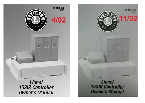
I Have the instruction book from 2001 and found the 2002 version on line.   Both begin by saying "your 1532IR will operate best at 12-20 volts (AC)."

However, the 2002 booklet has a section on "advanced wiring", which references DC power (attached).

I have grand kids here for an Easter egg hunt, but will soon head down to repeat those tests

Attachments

So here's the thing...

153ir 2002

No one likes a whiner; I get that.  But to peel another layer of the onion, there are apparently 2 versions of the 2002 153IR.  From your continuity measurements, it appears the 2002 versions may indeed be different in their wiring (based on measurements of a 2002 version in a previous OGR thread)....hence why I asked you to double-check.

I am slowly trying to unravel this insanity!

Bottom line is Lionel has changed the wiring instructions for the 153IR which impacts your ability to mix versions in the method I proposed.  They did so while maintaining the same SKU or part number.  And to my knowledge there is no "official" method to determine which version or revision you have.  So far, and as I've instructed, the best clue is the labeling of the two power terminals (either U-A, A-U, or unmarked).  But this is just my guess.  And wouldn't you know it, apparently yet another version of the 153IR came out last year which for all I know will have yet different wiring instructions and another revision date!  It's enough to make a grown man cry!

As to using the "oddball" 153IR in the middle section...

You still need to use the timer module.  Even though the direction does not change in the middle, the key feature of the timer module (when set to mode 1.1) is it performs its time-delay function irrespective of whether the trolley is still at the station.  In other words it starts the time delay function when the trolley arrives at the station.  A 153IR does not start its time-delay until the trolley leaves the station (moves away from the 153IR).  So without the timer module, the 153IR in the middle section would kill track power when the trolley arrives and simple keep track power removed forever (never starting its timer).

Attachments

Images (1)
  • 153ir 2002

1.  The two power terminals on units 2 & 3 are labeled A - U, not U-A

2.  Continuity

    On all three units there is continuity between accessory power and NC

     Unit 1  (as previously reported)  2001

  • Left to Com 2  Yes
  • Left to Com 1  No
  • L to NO          No
  • L to NC          yes
  • R to Com 2         No
  • R to Com 1         Yes
  • R to NO          No
  • R to NC          No

   Unit 2    2002

  • A to ACC power - Yes
  • A to Acc groud  - No
  • A to NO          No
  • A to NC          Yes
  • U to Acc Power   No
  • U to Acc ground  Yes
  • U to NO          No
  • U to NC          No


   Unit 3    2002

  • A to ACC power - no continuity
  • A to Acc groud  Continuity - YES
  • A to NO          No
  • A to NC          No
  • U to Acc Power  Yes
  • U to Acc ground  No
  • U to NO          No
  • U to NC          Yes
  • most importantly, in contrast to my earlier report, there is no continuity between NO & NC

3.  Clicking test

Unit 1 - as previously reported

Unit 2  Work-around the damaged U terminal

     Using ACC ground as a proxy for U,  it does click !

  • DC+ to A      with  DC- to ACC ground           Yes
  • DC- to A       with D+ to ACC ground          No

You've described this project as insanity, a big fish, the twi-light zone, the peeling an onion skin, and one other delightful metaphor I don't remember.  Thanks for your help.  I'm enjoying this tutorial.  I hope we have some clear sailing now.       

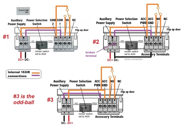
baird 153IR units 1 2 3 terminals

I reviewed your latest continuity and DC power results and drew up the above diagram.  Here's another one for you.  Add "suspension of disbelief" to what we have here.

So now it appears the wiring of the 2002 versions (your #2 and #3) are indeed different.  So now my previous hypothesis that you could see which 153IR version you had by simply looking at the left power terminal markings (U-A or A-U or unmarked) was WRONG.  You have to use a meter (continuity testing) to see what you have.  That's what I mean by suspension of disbelief.  Yikes!

BUT, with your specific combination of 3 153IR's, this may be one of those blue-moon events where the stars are in alignment...when 2 wrongs make a right...and two Wrights make an airplane.

Thanks to your methodical approach to the continuity and clicking measurements, I believe this can still work with DC powering all 3 153IR units.  I will next work on an exact diagram including broken #2 unit terminal.  Just wanted to assure you I'm still on-the-job!

Attachments

Images (1)
  • baird 153IR units 1 2 3 terminals
Last edited by stan2004

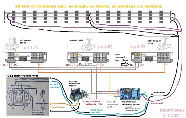
baird trolley 4-1-2021

Here you go!

I assume it's obvious you don't have to position 153IR units #1, #2, and #3 left-to-right.

Please note that 153IR unit #3 is wired 'backwards' on the left 2 power terminals.

The "you've got to be kidding" is that per your continuity measurements Lionel apparently released 2 versions of the 153IR during 2002.  I am speechless! 

Attachments

Images (1)
  • baird trolley 4-1-2021

That looks do-able - even for me.

I do have a rudimentary questions which I’ve been reluctant to post on a public forum for fear of further revealing my ignorance.

I will be able to follow the map you’ve laid out for me but I don’t entirely understand why it works.
A good place to start - in fact the fundamental question for me - is which parts of the system are DC, which AC, and WHY

it will be a while before I get back to you on this. I’ve completed all the wiring for the entire layout and have all the trolley wiring in place under the table. However it’s an above ground trolley on the second level. I have yet to finish laying the track on the first level and will do that first.

It’s clear to me now that my first adult layout probably should not have been so large, but it will be my last adult layout as well so I don’t regret anything except how slowly I have progressed.

The pressure is on though. Of all my grandkids the one who most loves trains (8 year old) and who loves to railfan all over the state said recently, “Papa, I hope you finish your train before you die!” I didn’t tell him that model railroaders almost never finish.

I’ll be back when I have a question or with pictures when I’m done - providing we both live long enough.

@Don Baird posted:

...

I will be able to follow the map you’ve laid out for me but I don’t entirely understand why it works.
A good place to start - in fact the fundamental question for me - is which parts of the system are DC, which AC, and WHY

...

@Don Baird posted:

Can I isolate the track at the end of the line to turn on a light or an accessory for the duration of time that the trolley is at the station?  When it reverses direction it would leave the isolated section turning off the light or deactivating the accessory ( likely a crossing light or gate).

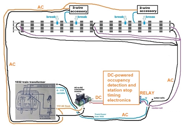
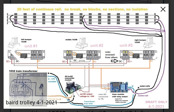
I think this diagram might answer both questions.

baird trolley dc ac mix

Once upon a time, you had a length of 3-rail track and a bump-n-go trolley that went end-to-end and self-reversed.  You could control the speed within reason by adjusting the throttle voltage. Because of the 3-rail track, you could use the insulated-rail method to co-opt sections of the track to activate an accessory when the trolley is over an insulated-rail section.  In principle, this method can handle either AC or DC. In your specific application the throttle happened to be AC and the trolley and accessories are compatible with AC so all's good.

But when you throw in station stop timing with sequencing "logic" implementation is generally easier using DC (solid-state) electronics.  Remember that the original Lionel station-stop used the AC-compatible nichrome heater/resistor switch that warmed up and cooled down to time the stop and start.  So while I'm sure we could have scoured eBay or wherever for such timing mechanisms I think that would have been riding the horse in the wrong direction.

So to take advantage of the modern and economical DC-powered electronics modules for optical detection, timing, logic, sequencing, etc., an AC-to-DC converter module was needed to provide such voltage.  As shown in the orange box, in the big picture the 153IRs and timing module simply takes DC voltage and controls a relay to connect/disconnect AC track voltage to the rail at the proper time.  The relay isolates the DC electronics from the AC track and AC accessory voltage.

The astute observer will correctly note that the 153IRs operate on AC voltage so why are they powered by DC?  This is one of those ignore-the-man-behind-the-curtain situations.  Yes, the 153IRs could be operated on AC...but then their outputs would be AC and would not be directly compatible with the DC timing module.  This would have required additional component(s) to convert AC-to-DC.  It's not that this is expensive (10 cents?) but in effect is performing the AC-to-DC conversion in two places.  I also know from past experience that mixing versions of the 153IR is a minefield...and in general it's easier to manipulate-combine multiple DC signals than multiple AC signals.

So the use of the DC-powered station-stop system does NOT affect your ability to use the insulated-rail method for your AC-powered accessories.

Early on you said you had a Menards lighted building that came with its own power adapter (presumably a 4.5V DC-output "wall-wart").  If this is one of the accessories you want to turn on/off when the trolley reaches an insulated-rail section, there are additional instructions.

Attachments

Images (1)
  • baird trolley dc ac mix

Thanks for the explanation. When we first began this conversation I would likely not have understood the expiation, but after working on this I do.
Regarding the stations, there will be three. One post-war lighted fright station, one small Rail King version of the traditional Lionel station (both lit with the little bulbs), and the third, Menard’s “Melrose Park Station which is lit with 10 LEDs. I had not imagined that their would be a way to tie the Menards station into the trolley arrival departure schedule.
The “wall watt” power source is not a problem as I have three different power strips located at various locations under the table for other Menards structures and some Christmas Village style structures in the mountain ski village.
However, I would like to confirm that I can use the traditional isolated (or insulated?) track for one of the traditional Lionel structures (one is to be located in a suburban area where the on off would be more obvious.
But if that could be established with the little Menards station, the effect would be dramatic!  The station operates on a 4.5 volt power source, drawing about 110 mA. I have the necessary power source, but I’m certainly interested in the possibility you raise.

@Don Baird posted:

...
However, I would like to confirm that I can use the traditional isolated (or insulated?) track for one of the traditional Lionel structures (one is to be located in a suburban area where the on off would be more obvious..

Yes.  If you are able/willing to "cut" the track to create insulated outer-rail sections...or use "prepared" track sections that have the insulated outer-rail...then you can use the Accessory AC voltage to power the accessories.  I'm sure the terminology-police are not happy but when used in the context of O-gauge trains, the terms insulated and isolated are used interchangeably.

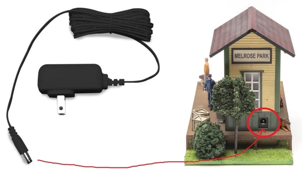
melrose station

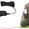
And just to be clear, your present situation is something like the above.  You have a wall-wart adapter (like on the left) and you have an illuminated Menard's structure powered by said adapter (like on the right).

Attachments

Images (1)
  • melrose station
Last edited by stan2004

As for the Menards building:
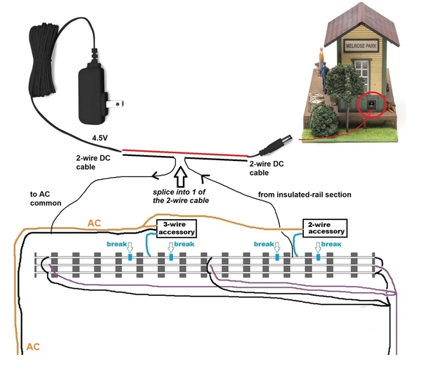
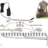
melrose station cable splice

Only the accessory portion of the wiring is shown above to reduce diagram clutter.

The method shown above is arguably the simplest from a technical standpoint but seems to confuse folks to the point where they don't believe it can work so they don't try it!  It's another one of those ignore-the-man-behind-the-curtain scenarios.

Step 1. I don't have a close-up of the Menards 4.5V DC-output power adapter but presumably you can easily splice into one of the two wires.  It actually doesn't matter which of the 2 wires you splice and I just happen to use "black" and "red" more to suggest this is DC; in all likelihood the cable will have stripes on one wire, or be "ribbed" on one wire, or whatever.  Again, it does NOT matter which one you splice into.  More on this later.

Step 2. Connect the transformer side of the splice to AC common.  Connect the plug side of the splice to the insulated rail section.

That's it.  Now when the trolley sits on the insulated rail section, the Menards building will turn on with 4.5V DC power from the wall-wart.  As shown in the above diagram, I purposely left a placeholder called "2-wire Accessory" on the same insulated rail section.  This is to show that you can still connect other conventionally powered accessories!  So for example the DC-powered Menards building could turn on as well as your RailKing building.

----

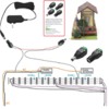
A minor variant to above is to use a pair of screw-terminal wiring adapters (about 50 cents each in small quantity).
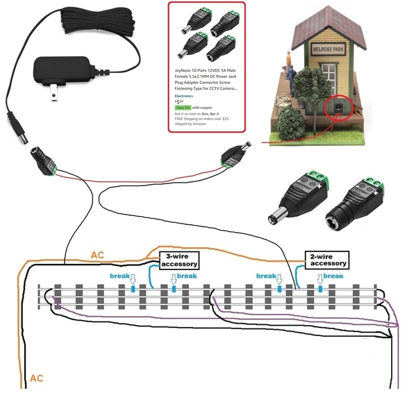
melrose station using screw terminal adapters

The electrical functionality is the same as splicing the cable...but as the adapters are coded "+" and "-" it could be some level of comfort to choose the "-" wire to tie together with the Accessory/Track AC common.  Again, it doesn't matter which of the 4.5V DC wires goes straight-thru to the Menards building.  I figure it is unlikely that the length of cable on the Menards transformer is long enough to reach your station anyway.  In other words, the screw-terminal adapters provides a way to make an "extension cord" of arbitrary length.

-----

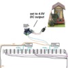
Another completely different tack is to convert the Menards building to Accessory AC voltage operation.
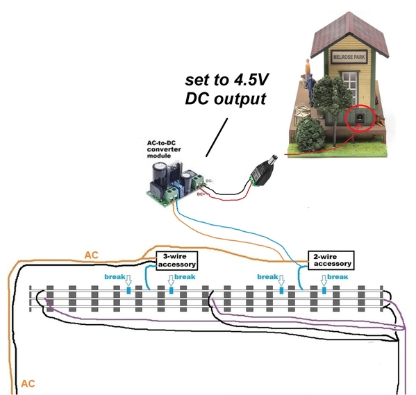
melrose station using ac-to-dc converter

If you bought more than one of those AC-to-DC converter modules, you could use one set to 4.5V DC output.  Then you have what amounts to a traditional AC Accessory powered building and you would hook it up to the insulated rail section just like a 2-wire accessory.  I'd think this could simplify wiring as a single train transformer powers all-things-trolley.

Attachments

Images (3)
  • melrose station cable splice
  • melrose station using screw terminal adapters
  • melrose station using ac-to-dc converter

I’m in the home stretch on all this wiring but am wondering about the the 10 to 15 feet of 20 awh solid core wire I have running between the modules and the 153IRs

I used the solid core wire because it fits in terminals more easily than stranded wire. In each case however the wiring traces from the modules to a terminal block where the lines split off in three directions toward towards the 153IRs. I could easily switch to 20 gauge stranded wire at that point, and switch back to solid  core wire immediately before the 153IRs  

Would the superior conductivity of stranded wire be an asset?

Relative to the Menards building, I’ll likel be following diagram #2, definitely NOT # 3

The 153IR modules draw much less than 1 Amp of current.  #20 stranded or solid is more than adequate conductivity-wise.  I suggest whichever method is easier for you installation-wise.  Likewise, if going with Menards diagram #2, the Menards station also draws much less than 1 Amp of current.  Again, if #20 is what you have (stranded or solid) you're good to go.

Re:  fuses/circuit breakers

you may have noticed my post about melted wiring and carpet under the Cristmas tree. I was using fastrack with my ZW.   And my grandkids  were regularly derailing the train

I’ve replaced all the feeder wire on that layout. Members of the forum advised me to use - some said fuses, others circuit breakers.

on the layout we’ve been working on I assume that fuses would go on each of the four lines on the ZW (with lower amperage on the accessory line?).  And none on the common ground  

what about the 1032?  U provides the variable speed power. BC the fixed.

Both transformer have built in fuses to protect themselves

Stan 2004

It’s been a couple of years since you helped me create this trolley system which has three automatic stops  IMG_6953You will remember that I was using a a 1032 as a trolley only source for everything trolley related while two mainlines and the remaining accessories are powered by a ZW.

NOW Im adding another mainline. Can I do the following (with the two transformers in phase).

1.  Use the 1042 B-C combination to feed the AC/DC conversion, the 153Rs, and (the timer module?) as the diagram shows;

2. Power the trolley from the b or c posts on the ZW

3. Power my third mainline from the A - U posts on the 1032?

I want to do this so I have a whistle control on the third line  

4. If so, what modifications on the wiring are necessary.

5. should any thing coming out of the 1032 be tied to the common ground bus.
Don Baird

Attachments

Images (1)
  • IMG_6953

Add Reply

Post

OGR Publishing, Inc., 1310 Eastside Centre Ct, Suite 6, Mountain Home, AR 72653
800-980-OGRR (6477)
www.ogaugerr.com

×
×
×
×
Link copied to your clipboard.
×
×