Hello! Does anyone have a wiring manual for this? Every time I wire it up, it gets super hot and starts steaming. I did read that the ground is a spring connected to a metal pole so I re wired it and it still gets super hot. It melted some of the housing... I do have it running off an MTH block connected to the DCS on fixed voltage so maybe its getting too many volts?
Replies sorted oldest to newest
Picture or two of the issue?
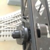
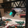
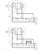
First picture is the melted part. Second is how the wires on the bulb are and third is how it’s wired. I have a ground on the spring and white wire and power on black. I did have the ground on black at first but same issue
Attachments
Does it have bulbs or LED's?
I'm wondering if it is designed for use with an insulated rail to trigger the Green/Red and you have wired it as a short circuit somehow. This is all I've discovered.
It’s pretty old so I would assume bulbs. It the box it did have a little piece of track in it. BUT it was K line track not fastrack. Any idea why it would need a block track section? It seems like wiring the way I have it and wiring to the track would be the same
Are you running this at 18 to 20 volts constant with maybe 14 volt light bulbs?
Yes, the DCS track voltage is way too much for the bulbs in this. The preferred method is to use adjustable/programmable or fixed accessory voltage set high enough to just illuminate them for satisfactory appearance.
I'm wondering if there is a power connection plus an insulated rail connection for each side with one common ground connection for the entire bridge? Hopefully someone here has one and can answer your question.
Well I hooked it up to a regular transformer and put it at medium and it still got way hot![]()
I’ll see if I can find some LEDs that’ll work. Anyone know what kind of bulb these are?
Attachments
They look like the 1447 - Town & country has them in red and green not the painted get 18volt
The manual linked above will describe how to connect
I ordered some LED e10 base bulbs. Will update once they come!
Jack118711 posted:I ordered some LED e10 base bulbs. Will update once they come!
good choice - simple way to update and eliminate heat from command voltages
They work quite well! Only issue is they are too long so the cover doesn’t go on... always something!
Attachments
Jack118711 posted:Well I hooked it up to a regular transformer and put it at medium and it still got way hot

Did you try something lower than "medium"?
So when you adjusted transformer for minimum acceptable brightness, it was still too hot? Kind of makes you wonder how the design ever worked in the first place!
stan2004 posted:Jack118711 posted:Well I hooked it up to a regular transformer and put it at medium and it still got way hot

Did you try something lower than "medium"?
So when you adjusted transformer for minimum acceptable brightness, it was still too hot? Kind of makes you wonder how the design ever worked in the first place!
Exactly!! It would burn too hot even if it was barely lit up
Jack118711 posted:They work quite well! Only issue is they are too long so the cover doesn’t go on... always something!
I had the same problem with the 'round top' LED bulbs in my Lionel die cast bumpers. Found a source that had 'flat top' LEDs and those worked perfectly. Unfortunately, it looks like that site is no longer functioning. Maybe a search on ebay or elsewhere for the flat top style.
As I recall my bumpers have the 'bayonet' type bulbs, but the source I had carried both the screw type and bayonet type LEDs so I know they were both out there at one time. Although they may not still be available now? I will do some searching and see what turns up. I'd like to have more myself.
One other thing (probably a dumb question too), but you didn't by chance order the 'large top' bulbs? I did notice the linked site had the 'large type' bulbs toward the end of the list...just a thought here.
Did you ever get a copy of the original instructions?
These should work better for you: http://stores.towncountryhobbies.com/led-1447g/ The lens hood should fit over these, this link is for green: and this link is for red: http://stores.towncountryhobbies.com/led-1447r/
Marty
BobbyD posted:Did you ever get a copy of the original instructions?
Nope!
Martin Derouin posted:These should work better for you: http://stores.towncountryhobbies.com/led-1447g/ The lens hood should fit over these, this link is for green: and this link is for red: http://stores.towncountryhobbies.com/led-1447r/
Marty
$10 for shipping!? Well I’ll probably order them anyway. Thanks for the link!
rtr12 posted:Jack118711 posted:They work quite well! Only issue is they are too long so the cover doesn’t go on... always something!
I had the same problem with the 'round top' LED bulbs in my Lionel die cast bumpers. Found a source that had 'flat top' LEDs and those worked perfectly. Unfortunately, it looks like that site is no longer functioning. Maybe a search on ebay or elsewhere for the flat top style.
As I recall my bumpers have the 'bayonet' type bulbs, but the source I had carried both the screw type and bayonet type LEDs so I know they were both out there at one time. Although they may not still be available now? I will do some searching and see what turns up. I'd like to have more myself.
One other thing (probably a dumb question too), but you didn't by chance order the 'large top' bulbs? I did notice the linked site had the 'large type' bulbs toward the end of the list...just a thought here.
These were just EBay specials to see if the base was right :-)
So with the smaller sized LED bulbs is this "case-closed"?
I don't understand how the fixture can over-heat when the bulb is barely glowing. Unless there is some undesired resistance in the spring, contact, connector, whatever. The current is low enough with the LED bulbs that the heat is acceptable...but becomes material with the higher-current incandescents. I would think some voltmeter measurements could isolate the problem...but not worth the bother if you have a solution in hand.
I don't know how Town and Country got in there, I use these from Auto-lamination, http://www.autolumination.com/...nverted_led_bulb.htm I have been using their bulbs for over 15 years. Been very happy with them... Shipping is about $5.00
Marty
I'd ask one of the "bay" guys if he'd copy the instructions for you.
Martin Derouin posted:I don't know how Town and Country got in there, I use these from Auto-lamination, http://www.autolumination.com/...nverted_led_bulb.htm I have been using their bulbs for over 15 years. Been very happy with them... Shipping is about $5.00
Marty
Those look just like the ones I have with the flat top, but they were 18 volt AC or DC. (I have command control only, all 18 volt.) The ones linked here are only 14 volt. I looked at their site and they have also some 1445 and 1447 18 volt LED bulbs that look different than the ones I was getting from my now gone supplier. If they are as shown in the picture on the 'Auto...' site they just might work in the Lionel bumpers and I am guessing maybe the OP's signals as well?
Per list of replaceable parts, the bulbs are 18V. A gold star to anyone who can explain the purpose of the 75 ohm ceramic resistor in the woven heat sleeve.
Attachments
stan2004 posted:Per list of replaceable parts, the bulbs are 18V. A gold star to anyone who can explain the purpose of the 75 ohm ceramic resistor in the woven heat sleeve.
After using the LEDs, that thing was getting SUPER hot. So I removed it and it still works fine. It’s really odd... it’s filled with what seems like white chalk
Well I figured out a way to get the cover on and used some electrical tape to cover the burn holes... anyway I’m quite happy! The LEDs work the DCS as well.
Attachments
stan2004 posted:A gold star to anyone who can explain the purpose of the 75 ohm ceramic resistor in the woven heat sleeve.
As Mr. Spock once said on Star Trek:
My "guess" would be valueless.
I give up! What's it doing in there?
Still, my best "guess" would be over-voltage protection (voltage spikes) from derailments.
Well it sure works well without it! It must have done something though since it got hotter than my fiancé *wink*
Thanks to Stan's promise of a gold star (and my own curiosity), I spent way too much time on this last night.
Having never looked at one of these first hand, and not having anything beyond the pictures to go by, this is what I came up with.
The wiring under the base is deceiving, it does not correlate with the two bulbs equally. To have the GRN bulb ON, current flows from terminal #3, through both the RED bulb and the 75 ohm resistor, to the GRN bulb, then to the spring terminal (#2). In this parrallel/series configuration, current through the RED bulb is low enough as to not illuminate it. To light the RED bulb, terminal #1 is connected to common through the isolated rail and the train's wheels. Current is still flowing through both the RED bulb and the 75 ohm resistor, but this creates 0 volts on both sides of the GRN bulb, thus turning it OFF.
At first I had calculated the flow in each scenario using the published figures for a #1447 bulb (18 V, 150 mA, 2.7 W). But because of the difference in resistance that occurs in an incandescent bulb at voltages other than those specified, I decided to load this into a simulator to see how the bulbs behaved.
Results @ 18 Vrms:
GRN On RED On
GRN bulb = 1.8 W 0 W
RED bulb = 305 mW 2.7 W
75 ohm R = 221 mW 4.34 W
Less than 1/4 Watt from the resistor with the GRN aspect displayed. However, if a train holds the signal RED for a prolonged period, the resistor is producing 4-1/3 Watts.
Jack, I think that removing the resistor was the way to go, given the wasted power and extra heat produced. When using a relay to change aspects it would need to be removed anyway.
> Are the terminals under the base marked?
Dave
P.S I could be wrong ![]()
Attachments
I think you deserve more than a gold star for that!! And yes they are labeled.
Hmmm... I wonder if having that removed would lower the temp of the regular bulbs.........
Dtrainmaster posted:Thanks to Stan's promise of a gold star..
Extra credit for the simulation results and nice diagrams!
As I see it, there are two issues. First was the "melting" issue at the signal head Jack showed in his first picture. Even though the parts list shows 18V bulbs, I'm thinking it was probably designed for 14V AC Accessory voltage which be a ~40% power reduction. I'm still not clear on why it burned too hot when barely glowing; unless you meant the mystery resistor in the base burning too hot.
The 2nd issue is the 75 Ohm, 5 Watt resistor in the base. I suppose the power-rating of the resistor is also a clue. 18V across 75 Ohms is ~4 Watts. So clearly the resistor was rated for full track voltage which as Dave shows is exactly what happens when Red is on. I also suppose if we had access to the instructions, we would have seen that this signal only requires an insulated-rail to operate both aspects. I suspect most guys now use relays, ITADs, 153c contactor plate, whatever with dual-outputs to separately power red and green. Until I stumbled across the parts list and the resistor, I was assuming it was just two bulbs.
I think with some experimentation you could use those LED replacement bulbs and come up with a resistor of much lower power rating (maybe 1/2 Watt or so, and maybe a resistance 5-10 times greater than 75 Ohms) that you could wire in parallel with the Red LED bulb so that you can still use only the insulated rail to select between Red and Green.
I realize a couple bucks for the LED replacement bulbs is essentially a plug-and-play solution. OTOH, if you're a DIY-enthusiast, this reminds me of the modern red-green 1-wire (insulated-rail) technique of "starving the Green LED." That is, Red LEDs turn on at about 2V, Green LEDs turn on at about 3V. So if you have a Green LED on, then put a Red LED in parallel with it, the Red LED will turn on and extinguish the Green LED because the voltage across the two LEDs will clamp at 2V thereby starving the Green LED. So you could buy some inexpensive red and green 8mm or 10mm LEDs (or whatever size fits in the signal heads), add 25 cents of parts, and make you own low-power signal head that can switch with just an insulated-rail (no relay, no ITAD, no whatever).
Attachments
Jack118711 posted:Hmmm... I wonder if having that removed would lower the temp of the regular bulbs.........
No.
I'd still be interested in seeing the bridge wiring instructions. I've got to believe they explain how to use a relay (NO contact to Red, NC contact to Green) in which case the resistor is not necessary.
Jack118711 posted:... And yes they are labeled.
And those labels are ?
WHT wire _______
BLK wire _______
Spring _______
Dtrainmaster posted:Jack118711 posted:... And yes they are labeled.
And those labels are ?
WHT wire _______
BLK wire _______
Spring _______
Lol oops. It’s just labeled 1,2 and 3


