
Hello all,

First time poster long time lurker.

I am looking for a simple solution for LED lighting in my buildings.   The current LEDs were from battery operated Christmas strings.  This worked great because they came with an 18 hr. off six hr. on control module.  My train is a shelf layout around my family room and I liked that the lights went  on at a slightly different times around 6pm and turned off around 10pm.  The batteries only lasted about three months and changing them got old quick.  So I moved the modules to a remote panel and added a DC power supply and soldered leads into where the batteries were.  Life was good again.  This only lasted a year or so and then the modules started to fail.  So out with the modules and in with the 24 hour timer.  All the lights now go on an off at the same time but I could live with it.  Now the LEDs are burning out.  I am down to only a few buildings and its time for a new solution.   Attached is the current wiring diagram for an overall perspective of the wiring setup.  I like the idea of the strip LEDs but that would mean changing the power supply.  Adding adjustable time delay modules back in would be great also if someone knows of a small module that would work.

Attachments

Images (5)
  • wiring diagram
  • panel
  • buildings
  • water tower
  • shelf
Original Post

Replies sorted oldest to newest

wiring diagram

A few questions so I understand where you are and where you want to go. 

1. Your photo shows what appears to be a bundle of twisted-pair cables from panel to shelf.  It looks like maybe AWG 24 wiring?

2. By having multiple (you show 5 in diagram above) pairs of "long wires," is your ultimate objective to have (up to) 5 shelf accessories turning ON and OFF independently and at different times?

3. You have 4.8V DC at the panel.  I don't understand how you "adjust" the voltage up at the accessories?  Are you depending on the voltage drop in the long runs of wire (~150 feet round-trip) as the sole-method of reducing the 4.8V down to 3V (or whatever)?  Or are there other components on the shelf (such as resistors) other than LEDs?

4. You show a 3V DC output on the shelf with nothing connected (no building, no windmill).  Presumably this was measured with a meter?  If using a meter as the only "load" on the 2-wire cable that started at 4.8V DC, even after 80 feet it is essentially inconceivable that the voltage would drop to 3V.

5. The windmill is labeled 6-12VDC.   Is this "just" connected to one pair to the panel...and then the voltage is what it is?  That is, it will be something less than 4.8V DC depending on the drop from the long run of wiring.  Is this what you want or do you really want control over the windmill RPM?

6. Finally, you mention a "simple" solution.  How does "simple" translate into budget?  Are we talking $10 or $100 or ??  And by "simple" does this mean soldering is off the table?

Attachments

Images (1)
  • wiring diagram

Med,  thank you for the parts suggestions.  Seems I still have a little to learn before I order parts.  See below.

Stan2004,

1-the wire is a 22/12 conductor cable.  Wires were twisted into 6 pairs on the ends not in the cable.  Currently using 5 pairs.

2- eventually all six pairs will be used as I add more buildings.  I also have other spare wires run for future accessories.

3- there are no resistors at the ends of the wires.  I do not now if there are resistors in the LEDs.  Could be why they are burning out.  Kind of why I’m here looking for help.

4-  I checked voltages at the ends of the wires today.  The longest wire run to a building with all LEDs not working anymore was 4.7v. The second longest run was 4.07v but still has a few LEDs working.  The third building that the LEDs  are still working was 3.01v. In the past I must have measured the voltage with the LEDs hooked up. You are correct about the voltage drop. No drop in the runs with nothing hooked up.

5- the drawing was showing the operating specs for the motor.  It is connected to 1pair. It does work at the lower voltage.  I’m not looking to control the speed. Just want it to run at a realistic speed.  It only runs occasionally when I run the train. Separate switch.

6- perhaps simple was not the best choice of words.  I read a lot of post on LEDs and watched some videos.  My background is in industrial control system. Installation testing and commissioning. The electronics were figured out by some one else. Maybe I am making this too complicated, information overload, or a lack of critical thinking skills.  There is probably a dozen ways to accomplish my goal. I went cheap and easy last time.  Soldering is not a problem.  I’m looking for reliable parts that will work together for more than a year or so.  I am more concerned with reliability and longevity than cost.  I’d rather build than buy where possible including the electronic.  I just need to know what parts to use.  That is the part of this hobby I like. Experimenting is not my favorite thing to do.    

What I was unsure about is are the LEDs wired in parallel or series in the house and could each house be wired to a common buss.

I appreciate you taking the time to dig deeper to get the information necessary to give good answers.  

... There is probablya dozen ways to accomplish my goal.

Or more! 

So this being a discussion forum, here's my plan-A, plan-B approach.

Plan A.

1) Check your 5V DC power supply.  Does it have an adjustment control?  Usually these so-called "open-frame" supplies allow you to adjust the output voltage by, say, +/-10%.  In other words, by turning a small adjustment knob you can set the 5.0V (nominal) output to 5.5V (+10%).   I don't like how you only get ~4.8V DC out of your 5V power supply!  If as you look at it you see the nameplate spec on how many Amps/Watts your supply can put out, then please post it.  It looks like you have maybe a 5V, 3 Amp supply (5V x 3A = 15 Watts) but hard to tell.

2) If your supply can be adjust to, say, 5.5V DC, then I believe you can send 5.5V DC up to the shelf and have enough voltage (after wire drop) to adequately illuminate 5V LEDs.  What do I mean by 5V LEDs?  This is the key.  As MED points out, you can buy pre-wired 5V LEDs; these have built-in resistors so that the LED itself sees a suitable (safe) voltage when you apply 5V to the wire terminals.

If I were doing it, I would simply use 5V LED warm-white strips.  These have the "built-in" resistors so you can safely apply 5V directly to the LED.  You should expect to pay at most, say, 5 cents per LED.

5v dc warm white light strips - for example 60 LEDs per meter

Again, in the plan A/B school of thought, you can try 5V LED light strips, cut-to-length, and see if you get adequate brightness with the long wires from panel to shelf.  It appears you are familiar with these strip...but to summarize, you can cut them to length from a single LED to 10 or more LEDs.  The strips themselves have the LEDs in parallel.  Each LED is, as you note, a ~3V LED so on the strip there is a built-in resistor PER LED...so that applying 5V DC does not damage or burn out the LED(s).

Plan B.

I purposely skip over the techno-boredom about AWG 22 wire and how much voltage it "theoretically" drops over a 80 foot cable run blah blah blah.  It's tedious and the theory rarely matches the reality of real wiring issues with crimped connectors, terminal blocks, and so on.  And yes, this is just my opinion.

Here's what I would do.

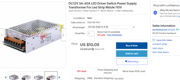
Forget the 5V power supply.  Get a 12V power supply.  We can get into specifics but this would be maybe $10 all-in for more power than you would ever need!  And I don't know if you have kids/grandkids poking around your panel ... but I see how you shielded what appears to be otherwise exposed 120V AC line voltage!  Good for you!

Go ahead and use your existing cabling.

The idea is to employ point-of-use voltage regulator modules to deliver exactly 5V DC inches from your buildings.  This is "classic" power distribution architecture using a "high" voltage distribution bus with so-called "local regulation."  This is how it's done in the real-world!  High voltage distribution with step-down to use-able voltage at the local or point-of-use (which in your case is the shelf buildings/accessories).

stepdown regulator

A 5V LED strip is essentially a bunch of LEDs in parallel.  The above photo shows how you can cut a 5V LED in increments of one (1) LED.  There is a single LED in parallel with a strip of 6 LEDs.  Of course the 6 LED strip consists of 6 LEDs in parallel.

I realize you said you're not interesting in "experimenting" but only speaking for myself, I would try Plan A to see if you get adequate illumination using multiple 5V LED strip sections (in parallel) after the long wire drop.

Anyway.  If you step up to a 12V DC supply down at the panel, the point-of-use voltage regulator modules are less than $2...or about $3 if they include a DC voltmeter as shown above.   These modules convert whatever the 12V DC voltage drops to at the end of 80 feet (or whatever) of cable to exactly 5.0V or 4.5V or whatever.  And these are Amazon prices with US shipping...so if you are willing to wait a bit for Asia shipping you can save a few bucks.

dc dc stepdown with and without voltmeter

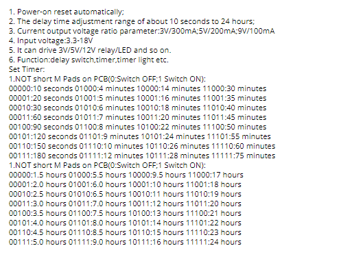
In the category of "but wait, there's more" you will find a wider variety of timer modules that operate at 12V DC than 5V DC.  That is, I wouldn't be surprise to learn the automotive market is the largest market  for DIY timer modules!

But to be clear.  Ask more questions and  by all means challenge my critical thinking skills.

Hopefully others might contribute their own Plan A, Plan B, etc. !

Oh.  And, as others have mentioned, there are buckets of different DC timer modules that can do the job.  I purposely left this out of the discussion as I don't think this is what should drive the "architecture" of your system.  Cart-before-the-horse.

Attachments

Images (3)
  • 5v dc warm white light strips - for example 60 LEDs per meter
  • stepdown regulator
  • dc dc stepdown with and without voltmeter
Last edited by stan2004

Great.  Only two options.  I like that. 

There is no brand name or specs on the front of the power supply.  They may be on the back but didn't remove it.  So I ran a few checks with a multimeter.

No load with only the display meter hooked up = 5.66v.  Wondering about the accuracy of the of the display meter I checked to with a Fluke 85 = 5.55v.  Sight variation but I was not as concerned with accuracy but more on a change over time.

Directly off the power supply with nothing hooked up =5.7v.

Adjusting the output pot no load = 5.77 to 4.5v.  With the current load hooked up = 4.89 to 4.02 drawing .43amps.

It is an old power supply given to me a long time ago.  So it can go away.  I like "option B" a lot better anyhow. 

The panel is mounted on drawer slides under the bar sink allowing it to be pulled out to work on. At first I mounted it on hinges but got tired of moving stuff out of the way to swing it to the front.  While it is not accessible to kids the wife does store stuff under there and I would never hear the end of it if she got shocked.  The timer has a cover that was removed for pictures.

So on with plan B.  Did I say I like this option?

I  really like the "point-of-use voltage regulator" ideology.  This just makes so much sense.  It also solves my windmill problem of being fed with less than the recommended 6v.  I always worried about letting it run to long as some motors will overheat when supplied with inadequate power. Not sure about these little motors but it can be a big deal with large motors.

I like the voltage regulator that you posted.  Small and cost effective.  As they will reside up on the shelf I don't see the display being as beneficial as it would be if they were in a  more easily monitored location.   I found on eBay from California LM2596(S)at 10 for $11.94.  The only spec difference that I can see is that the S model list the output current at 3amp.  Thoughts?

Am I on the right track for a power supply?  8 amps. 

And for LEDs

LEDs

Both of these are sold by the same vender making it a little more convenient.

I do appreciate your time and information.  I feel like I'm finally on the right track again.  I had gotten tired of searching and reading LEDs post after post.  Watching videos.  Never finding the big picture that put  all pieces together for me.  You Sir, seem to have a knack for that and I am grateful.

The right power supply with the right voltage regulators and the right LEDs. Who would have thunk it could be so simple.

Attachments

Images (2)
  • power supply
  • LEDs

I think your 5V supply has got to go.  A "generic" modern power supply should provide, say, 1 or 2% "load regulation" meaning it should stay within 1 or 2% of its output voltage as you vary the load over its specified operating capability.  If, measured right at the power supply, the voltage varies 4.89V to 4.02V (that's over 15% change) by a modest load of 0.43 Amps...then there is no joy in Mudville.

That's fine to use the less expensive "meter-less" DC-to-DC converters.  If you can get converters for about $1 each from a U.S. source that's pretty good.  You may have noticed that the less expensive converters do NOT have screw-terminals for the voltage input and output so you will need to solder wires.  That's a to-each-his-own cost/hassle tradeoff to which I have no comment!

The (S) versions of the converter are fine. There's a story there but is just a distraction.

The bigger "systems" issue is your choice of 12V LED light strips when I was assuming you'd be using 5V strips.  We never got into the big picture of exactly (or even approximately) how much LED power (whether measured in Lumens or Watts) you need to light up your buildings -structures.  Very few OGR folks would know a Lumen if it smacked them in the face.  I think most guys have a vague idea of how bright a 7 Watt incandescent nite-lite is, or how bright a 40 Watt incandescent lamp bulb, etc.  The point it's very difficult to specify how much lighting power you need for LED buildings. Is a 12V x 8 Amp = 96 Watt DC supply enough power?  Good question.  If I told you to plan for, say, 50 Lumens per Watt using LED strips...so that you are provisioning for 5000 Lumens does this even sound like we're speaking the same language?! 

Anyway, here's the thing.  Those $1 DC-to-DC converters have a voltage "tax" where they require in the neighborhood of 2-3 Volts MORE input voltage than the desired output voltage.  So if you have 12V in, and 5V out, then no problem.  But you cannot have 12V in, and 12V out...or even 12V in and 11V out.  You can probably adjust that 12V open-frame power supply to, say, 13V DC output.  But after the voltage drop from 80 feet of AWG 22 cable, there will NEVER be enough voltage at the DC converter inputs to sustain/regulate 12V DC at the output.

It is absolutely the case though that 12V DC LED strips are way more plentiful and cost effective per LED, per Lumen, per anything than 5V DC LED strips.  There is a "push" if you want to call it that where USB LED strips (5V DC) are trying to make their mark in the world...but I just don't see it de-throning the 12V light strips.  Of course we're still talking pennies per LED in either case so it's really a non-issue in your case.

BUT, if you want to go with 12V strips I'm fine with that.  You should use a main DC power supply of, say, 15V or 16V DC or more given the voltage drop from panel to shelf...and the aforementioned voltage "tax" that the DC-to-DC converters need.

I have used on multiple occasions 90 Watt "laptop chargers".  Heck, you may even have one of these lying around in a drawer.  Otherwise, I have purchased this specific 90 Watt adjustable voltage charger from this exact U.S. seller on eBay...$10 free shipping:

universal laptop charger 90Watts 12-24V DC output

I notice in one of your photos how you sliced an AC cord to length on your 5V power supply input.  These laptop chargers come with awkwardly long (for your panel) AC power cables so you'd have to dress it accordingly or pony up a few bucks for a "short" AC cable as shown.  On the DC output side, you'd either have to splice into the DC output cable...or there are coaxial-to-screw-terminal adapters as illustrated.

But getting back to choice of 12V or 5V LED strips.  To repeat, you have MORE options and probably a lower per-LED cost with 12V strips at this time.  Note that the 12V strips must be "cut" in sections of 3 LEDs.  The 5V strips are "cut" in sections of 1 LED.  The LED strips come in various "densities" which means the number of LEDs PER cm.  Here's where you need to inventory your buildings/structures to see what makes sense.

OK, that's probably enough information overload for today!  Are we having fun yet? 

One idea that just bubbled up.  If you have been following OGR threads on buildings/scenery you will note that Menards and Lemax buildings (they use 4.5V DC) and Miller animated "neon" signs are popular.  The point is for a given 2-wire twisted-pair circuit to the shelf, nothing stops you from hooking up two (2) DC-to-DC converters...one putting out ~4.5V DC and the other putting out ~12V DC.  So to be clear, if you send 15V, 16V, or 18V DC from the panel up to a given distribution point on the shelf, you can have 2 regulator boards providing local regulation on that circuit.  One output (around 12V) can power your 12V LED strip(s)...or pre-wired 12V LEDs if you choose to use those instead.  The other output (around 4.5V DC) can power a Menards/Lemax/Miller lighting structure should you choose to add one to your real-estate holdings!

I could ramble on forever about this stuff. 

Can't wait to get into my ideas about timers to further demonstrate my expertise at spending other people's money.  LOL.

Attachments

Images (1)
  • universal laptop charger 90Watts 12-24V DC output
Last edited by stan2004

The voltage "tax" makes sense and I like the idea of being able to use only one LED for some of the smaller building so i will stick to the 5VDC LEDs as you suggested.  What is the advantage / disadvantage of selecting a higher voltage  16 or 18V instead of the 12V?  Higher voltage means more current available.  I would be able to add more accessories to the power supply?  I know there is a limit based on the wire size I have.  Many years ago I had been thru multiple different classes that covered ohms law and I struggled every time.  Hated doing the calculations. I would just remember the rules to pass the test.  And the theory seemed to change based on who was giving the class. I could never figure out if electricity flows from + to - or - to +?  If AC changes polarity with each cycle how does it flow at all? OK just kidding.  All I care about is if the circuit is complete it flows.

So know I know what I need for the LEDs, voltage regulators and a power supply. The discussion of the system architecture would not be incomplete without talking about circuit protection. What is necessary and where in the circuit makes the most sense.  Does a lap top power supply have any kind of thermal/over current protection?  My main concern will be protecting the wire from overheating as it does travel inside of an insulated wall from shelf to under the bar. 

Are we ready to talk time delays yet? Power is fun but controls are cool. 

I think it's safe to assume that any modern consumer electronics widget will have circuit fault protection.  In fact even the $1 DC-to-DC converter modules under discussion have built-in thermal shutdown to protect again faults like a short circuit.

What makes your circuit "interesting" are the multiple long cable runs.  That is, I can imagine a situation where you could have a short-circuit up on the shelf in one of the 6 circuits.  But because of the resistance in the cable, the power supply down below does not "see" the short-circuit but instead sees some non-zero wire resistance and says to itself, "hey, no big deal, I'll just deliver more current" (to within its Amperage capability of course).

To your point, yes, if you can up the power supply voltage at the base, you need less current to deliver the same Watts (or Lumens of lighting) up on the shelf.  So assuming we're going with Plan B (local regulation using the $1 converters), then I would absolutely go with a higher DC voltage...say 18V DC.  Here you can dust off the textbooks and re-examine Ohm's Law and such but let's just say you'll be better off (more efficient) running lower currents.

An inexpensive way to gain some peace-of-mind would be to put a 25-cent resettable fuse on each circuit from panel to shelf.  Like any "fuse" you need to choose its value based on the operating/fault current.  Perhaps you recall some of the readings on your Volt/Amp meter when you had full lighting and windmill operation.  I realize you now show about 5V and about 0.5 Amps.  That's "only" 2.5 Watts (W = Volts x Amps) albeit with a portion of your real-estate empire in the dark.

So with no further analysis, and almost more to carry on a discussion, I'll draw an arbitrary line-in-the-sand and suggest targeting a max current per circuit to 1 Amp.  If using 18V DC at the base, that's up to 18 Watts up the wire and depending on the wire length ~15 Watts available at the DC-to-DC converter.  There is some power conversion loss when changing voltage levels but you'd easily have 10 Watts of 5V DC power.  That will drive some 100 LEDs sections.  Lots of hand-waving here but just trying to get arms around the problem.

resettable fuse 900mA for about 35 cents

If not familiar with resettable fuses, they are widely available and inexpensive.  I found above using the sort-by-cheapest on eBay just to give you an idea.  The key parameter is the so-called Hold current rating which in this case is 0.9A which is close enough to 1 Amp.  In round numbers these devices will Trip at about double the Hold current...so at around 2 Amps it will open like a traditional fuse but is self-resetting so when you clear the fault it can live another day.  Another parameter is the voltage rating in this case 72V...so 18V is well within its range.

Moving on.  I'm not quite clear on exactly what you meant by having a timer trigger 15 minutes or whatever after turning on power.  And then earlier you mentioned some kind of lamp timer-like device that came on at about 6pm every day or whatever.

6-30v timer relay module

In any case, I can recommend the above DC timer module if for no other reason than to start a discussion.  I have used this module many times.  One nice feature is it operates over a relatively wide voltage range ... so could be powered by 12V DC or 18V DC.  Many timer modules are for 12V automotive applications and might have issues with 18V.

This module would be able to turn on or turn off after, say, 15 minutes.  Or it has a cycling feature where it can turn on for X minutes, then turn off for Y minutes, and loop forever.

Here's a short video of this module in action I made for a different OGR train application.  It's just to show the relative size of this widget.

So I can see one of these modules per circuit, placed in the base where you can access them as needed.

Then, suppose you placed a timer module on the shelf near buildings.  This module could alternate between two different DC-to-DC converters to apply "full" voltage or "half voltage" to a set of buildings so they change brightness (in addition to going on/off).

Also, I like your use of the term "control" in the discussing timing.  That is, once you "buy-in" to using these inexpensive electronic modules with Lego-like assembly, you might consider something like an optical trigger so that a timer module placed on the shelf triggers for some interval only when the train goes by.

Attachments

Images (2)
  • 6-30v timer relay module
  • resettable fuse 900mA for about 35 cents
Last edited by stan2004

Thanks for the great information on circuit protection. Resettable as apposed to fuses, I like that.

Currently I am using an Intermatic programmable timer to turn on at 6pm and off at 10pm daily.  The timer powers a receptacle with a train transformer and the current 5vdc power supply plugged in to it. The train transformer is only powering incandescent street lights and other lighted accessories that sit on shelves behind displayed trains.

My goal was to not have all of the building lights come on at the same time.  The timing between lights turning on would be just a minute or two until all are building are lit.  

Do the timing modules need to be powered all the time to retain the settings?  

In your video the reed switch is providing the trigger to start the sequence.  The two second delay on is the P1 time? The relay being energized for 10 seconds is the P2 time?

In your video application the trigger is momentary and it starts the sequence.  If the trigger is constant could/would the removal of the trigger also start a timed sequence?  Just wondering.

If I understanding the timer module, for my application I could use the intermatic timer to provide the trigger at a fixed time every day.   Each timer module would be set with a different delay on time of say a minute or two.  That would stagger5the light on. I would set the timer for minutes and a delay off  time of 240 minutes (up to 999) would give me a 4 hour on time for the light. The lights would turn off in the same sequence they were turned on.  First on first off.

I do have an optical triggered relay.  Bought it at a train show a few years ago. Seemed like a cool idea.  Haven’t figured out what to use it for yet.

All the "digital" timer modules of this ilk will retain their timing settings without power applied.  The parameters are stored in non-volatile "flash" memory as used in all modern consumer electronics.  There are some low-cost timer modules that have knob-adjustment (potentiometer) to set the delay times; obviously these too retain their time delays by "mechanical" memory.

Note that if trying to pair multiple "digital" timer modules, with the microcontroller technology used in the low cost modules, you will get excellent repeatability (to within a fraction of a percent)...but the absolute accuracy may be in the 1% range.  In other words, set two low-cost "digital" modules to 240. minutes and they may be off by, say, 2 minutes.

I bring this up with regards to your proposed scenario of first one on is first one off after 240. minutes.  You may need to fine-tune the modules.  You may need to set a particular module to 239. minutes to effect a 240 minute delay.  Or, you may need to set a different module to 241 minutes to effect a 240 minute delay.  Again, the repeatability will be better than the accuracy so once you make this adjustment, you should be good to go.  This is a your-mileage-may-vary and I'm sure there are digital modules with absolute accuracy in the fraction of a percent such that 240. minutes will be 240.0 minutes within a second or so.

The video was just a "proof-of-life" showing what it looks like when running and its relative size to O-gauge.  The particular module I showed has a wide variety of "modes" as described in the eBay listing.  I was not meaning to suggest the mode used in the video was applicable to your situation.  I do believe once I fully understand your timing requirement that this module has a mode that would apply.  I have spent some time trying to decipher the mangled English translations of the instructions for this and other similar modules.  For example, in this purposely blurry diagram I tried to sketch out the different modes and how the trigger starts, restarts, or even affects the timing.  Purposely blurry is because it's a work in progress that I think is correct but I learn something new just about every time I try it!  If this module is something you want to pursue, I will confirm it would work in your application.

purposely unreadable jz-801 timer modes

There are some modes that do NOT require a trigger at all.  That is, just apply DC power and its relay will open/close with the settable timing parameters.  Some modes are "re-triggerable" meaning if you apply a 2nd trigger while a timing operation is running, it will restart the timing thereby extending the over-all cycle.  There are some modes where, rather than the application of the trigger it's the removal of the trigger that effects some behavior.  And I've found on multiple occasion that the module may come with MORE modes than are documented in the eBay/Amazon/wherever listing description!  And so on.  Can get confusing.  But to some, the allure of finding out what's really behind Door #2 is part of the fun!

Attachments

Images (1)
  • purposely unreadable jz-801 timer modes

More great information.  You are very generous with your time and knowledge. It is greatly appreciated.

I understand the point about repeatability and accuracy.   My initial goal was to stagger the on time of the lights. Having them turn off in a staggered sequence would be an added benefit. Something I hadn't considered adding into the sequence.   

As far as timers go I am not married to any specific components to accomplish this goal. So i will rely on your guidance and expertise to recommend components.  Reliability and ease of use would be towards the top of my preferences.  Almost anything can be accomplished given enough effort, time and money. The question becomes the cost to accomplish the goal.

Whether the time delay is started by powering on the timer or a trigger would depend on if it is better or necessary to have the timing module powered all the time.  Since the timing module retains the timing settings on loss of power I am thinking it is not necessary for power to always be on.

The "mangled English translations" is one of the problems that i have had in the past when trying to figure out  these micro controllers. 

So looking and reading about the different delay timers for sale I came across one of these and had a thought. (don't say it, yes I'm having trouble seeing through all the smoke)

I am not exactly sure how this chip works but I am going to take a guess for the sake of our conversation about timing.

Currently one circuit powers two or three building.  If the programmable timer located at the base is used to power the circuit to the buildings could something like this "chip" be used to delay the power to the second and third building?  Or even individual rooms. The 5vdc from the  voltage regulator that lights the LEDs in the first building would supply the 5vdc to this "chip" located in the second building and another one in the third building.  It looks like the delay is set by adding a component (resistor or capacitor) to the left side of the board. If this is the case the value for the timing component could be calculated for different fixed delays of say a 30, 60, 90 seconds or 1,2,3 minutes and so on.  It would be a very cost effective means to add more control to each circuit.  It would also make it possible to give a more random look to the lights coming on.

For this discussion power is supplied to all the timers at once.  See if this makes sense.

Circuit #1 has 3 buildings labeled buildings 1,2 and 3.  Bldg 1 turns on when power is supplied to the timer , using a "chip" bldg 2 will be delayed 2 minutes, bldg 3 chip will be delayed 4 minutes.

Circuit #2 has 2 building. Buildings  4 & 5 - the circuit #2 timer output turns on one minute after power is supplied to the timers. Bldg 5 has a 2 minute delay chip.

Sequence of operation would be:

Building 1 turns on when power is applied to the timer. One minute later building 4 turns on when timer for circuit #2 output is energized. One minute later building 2 would turn on (2 minute delay from building 1), one minute later building 5 would turn on ( 2 minute delay),  and one minute later building 3 would turn on (4 minute delay from building 1).  This would give a more random appearance of lighting. Exact timing would not be critical.  More interested in the effect than precise timing. This same set up could then be used for another 5 building. By varying the programmable time delays relays slightly all ten building would turn on a slightly different times. 

Since I'm a visual kind of guy.

TD circuit

Or is that all just crazy talk. 

Attachments

Images (2)
  • TD sketch
  • chip
@BobbyD posted:

This has been an interesting thread to follow. Are there dimmable LED strips available?

LED strips can be dimmed by simply reducing the applied voltage.  For example, for the common 12V LED strips, they will dim as you lower the applied voltage until they are dark at about 8V (or so).  5V LED strips will dim down until dark at about 3V (or so).  So I guess the snarky answer to your question is "yes."

Separately, you may be thinking of 120V AC LED bulbs for your house making a big distinction about whether they are dimmable or not. It's kind of an apples-orange comparison having to do with how household lamp-dimmers evolved and related arcane techno mumbo jumbo.


..The "mangled English translations" is one of the problems that i have had in the past when trying to figure out  these micro controllers.

So looking and reading about the different delay timers for sale I came across one of these and had a thought. (don't say it, yes I'm having trouble seeing through all the smoke)


With these Asian-designed chips/modules, I've found it worth the time to try to find what I call the mother document...typically in Chinese.  From what I can tell, all the eBay, and even Amazon, sellers simply copy each other's mangled English...in some cases mangling the instructions even more until it's almost comical to read.

I am not familiar with the chip you refer, but for 15 cents I'll take the bait.

find the mother document

Sometimes you can find what might be the mothership of documentation and there may be some tidbits to be gleaned even without Chinese language skills.  Or, look for someone who has taken it on as a personal mission to figure it out...kind of like how I'm slowly unraveling the mysteries of the multifunction timer relay module.

I found this well-written (English) description by some kindred spirit.  My browser says it's not a secure website so be advised - I won't make it a click-able link but it was full of useful info:

http://westsideelectronics.com/delay-timer-ic/

Anyway, from what I learned this would be classified as a "delay-OFF" timer.  In other words, you apply power...the output immediately turns ON...the delay interval completes...and the output turns OFF.  So this is not what you want.

As I understand it, you want a "delay-ON" timer.  In other words, you apply power...the output remains OFF...the delay interval completes...and the output then turns ON and stays ON.

I did not look to see if there are 15-cent "delay-ON" timer modules.  That is, if I had them in hand I'd just tack on some cheap components to do what you want:

cascaded timer modules

For example, with the addition of a 5-cent resistor and a 10-cent transistor you can "invert" the output of the 15 cent module so that the LED(s) would turn ON some settable delay after 5V power is applied to the module.  Obviously we are entering the realm of soldering tiny components so it's not in everyone's comfort zone.  So in the diagram above, let's say the timing resistor on the left is chosen for 30 sec for the upper module and 60 sec for the lower module. 

Then, when 5V power is applied at 6pm by the Intermatic timer, the upper module's 5V LEDs would turn on AFTER a delay of 30 sec.  The lower module's 5V LEDs would turn on AFTER a delay of 60 sec.  More modules can be added.

Attachments

Images (2)
  • find the mother document
  • cascaded timer modules

Obviously the chip I used for the sake of discussing timing is not the best component to provide the fixed time delays I am looking for.   Seeking a better solution  I came across these. I believe these are a delay on device.  Seems like they may be not only a simpler solution but a more flexible solution.

Time delay is set by dip switch.  How neat is that? And they are still cost effective enough to add to each building.


Found these on AliExpress.  I have never ordered from them.  Says shipping is 30-50 days.   Ouch!  Any experience with them?

Looks like a plug would fit the 4 pins on this module.  Would you happen to know the name of that style of plug?

Attachments

Images (2)
  • mceclip1
  • dip switch settings

Add Reply

Post

OGR Publishing, Inc., 1310 Eastside Centre Ct, Suite 6, Mountain Home, AR 72653
800-980-OGRR (6477)
www.ogaugerr.com

×
×
×
×
Link copied to your clipboard.
×
×