Over the past years I have done many DCS upgrades.  Several people wanted bright white LEDs in headlights and backup lights.  My good friend Locolawyer is the guy I blame the most for this request.  Recently I have had members ask me to throw something on the forum instructing how it is done.  Very simple and very cheap to do.  On PS2 and PS32 boards the wires for the front headlight are light blue and purple.  Light blue coming from the number 5 pin on the 12 pin connector and the purple comes from the 2 pin on the 12 pin connector.  The rear lighting is a light green wire from pin 4 on the 12 pin connector and the purple from pin 2 on the 12 pin connector.  On front and back lighting, follow the purple wire to where your lights plug in.  The purple  is the hot wire and the corresponding wire that you need to put your resistor in on the light side of the plug.  Cut the wire and insert a 560 OHM 1/2 or 1/4 watt resistor.  Next cut the bulb off the wires and connect the longest lead from the LED to the other end of the resistor.  The long lead is plus.  Connect the other wire (negative) to the ground side and you now have LED headlight/backup lights.  I will outline this a bit better with a few pictures.


led3 014


The photo above shows left to right a section of 3/64 heat shrink, a section of 3/32 heat shrink, next a 3mm bright white LED.  This is Lionel p/n 6102045300, and a 560 OHM 1/2 watt resistor.


lled4 014


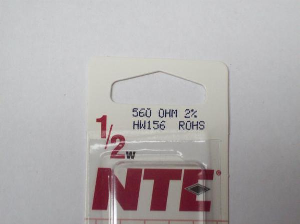
Above is the resistor I used.  You can buy what you need at many locations and they are very inexpensive.  No polarity is needed.


led12 019


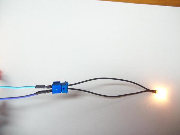
Above is a front MTH conversion showing the light blue and purple wires used in the front headlight.  This is the original incandescent light from the upgrade kit.


led4 010


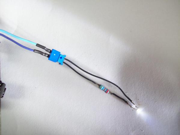
This shows the finished product without the shrink to show you the path of the purple wire to the resistor then to the LED.
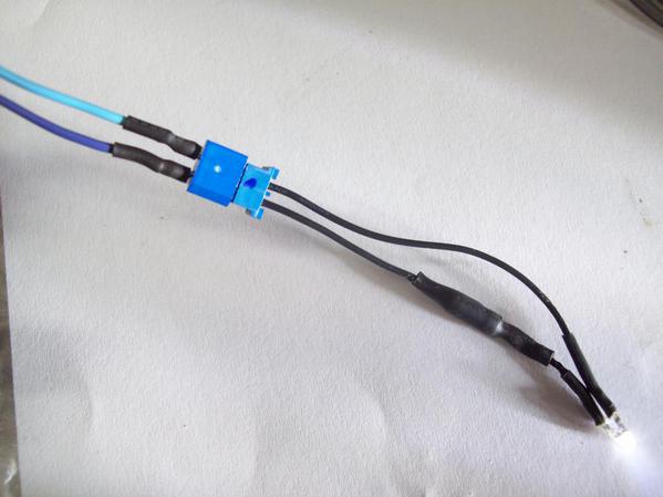


led9 002


This photo shows the final product with heat shrink installed.
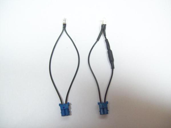


led9 013


This shows before and after.  You are out about 20 minutes of your time and about two bucks.  If you like the LED look, anyone can do it with no special skills.  The LED I used was from Lionel and the resistor from a local parts store.  You can use any manufacturer of the products.  I did some testing with these a long time ago with MTH R&D and the correct resistor we came up with was a 510 OHM.  You can go down to that if they are available to you.
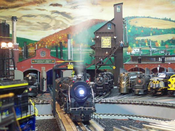


Locolawyer 024


This is an MTH PS1 upgraded Hudson for Locolawyer.
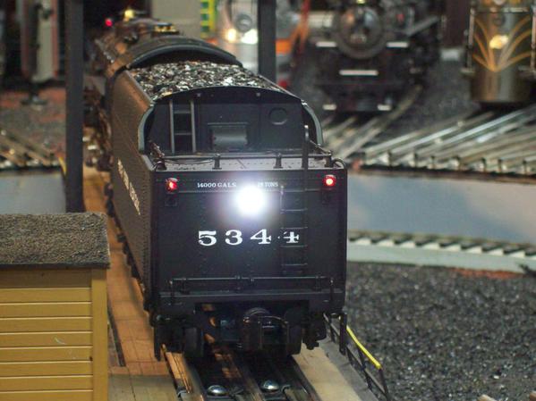


Locolawyer 040


The rear of the Locolawyer Hudson.

Attachments

Images (9)
  • Parts needed to convert to a LED headlight/backup light.: Left to right.  One length of 3/64 heat shrink tubing, next one length of 3/32 heat shrink tubing, next a 3mm bright white LED, and a 560OHM 1/2 watt resistor.
  • lled4 014
  • led12 019
  • led4 010
  • led9 002
  • led9 002
  • led9 013
  • Locolawyer 024
  • Locolawyer 040
Last edited by Marty Fitzhenry
Original Post

Replies sorted oldest to newest

Originally Posted by John H:

Weren't Protosound headlights run on 1.5 volts?

Only Diesel engines with access to the PS-1 board.  RK Steam engine with the PS-1 board in the tender used track voltage 18V bulbs for the headlight.  Premier Steam with a Constant Voltage board in the engine used 6V bulbs.  G

You can use any LED for the headlight, not just bright white.  On many, I use the warm white, especially for steamers.  If you want more than one light, you can drive a bunch of LED's off a single lighting output, the factory has a number of engines with three 60ma bulbs on the headlight circuit.  A white LED with a 560 ohm resistor draws less than 10ma, you could put eighteen of them on the headlight circuit and it would be less load than the stock incandescent bulbs.  Also, if you want brighter lights, you can go down to as low as 220 ohms safely, that gets you up to around 17-18 ma for each LED.

Last edited by gunrunnerjohn

To be clear, they are different!  Marty is talking about PS2 locomotives.


As George says, TMCC puts out half-wave DC in command mode and full wave AC in conventional mode.  Since the locomotive may drop into conventional mode with loss of signal, it's best to have a diode to protect the LED against reverse polarity as they don't have a high tolerance for that.  For TMCC I use a 470 ohm resistor and a 1N4003 diode.  Also, note that the lighting outputs of TMCC locomotives with an R2LC of C08 or later firmware is negative in respect to frame ground, keep that in mind.  That encompasses a large majority of the TMCC equipment.  Modular electronics with an R2LC of C07 or earlier, and any LCRU have a positive polarity lamp output.


Bob, the markers already have a position on the 8 pin connector at position 4 and 6 on a diesel.  In most MTH steam locomotives the front markers are run by a CV board.  This board will control all the necessary lights that are required in the boiler.  


If you go to an LED headlight, you could add more into it.  On an upgrade, you need to be a bit creative on what you need.  The world of upgrades takes in many locomotives built by other makers.   MTH are easy, some others not so easy.


The LED is a great tool to get what you need for an upgrade.   Many locomotives made by other than MTH usually use some sort of CV board to control the headlight and front markers.


The MTH upgrade kit is very universal and a great bang for your buck.  I would suggest if you are thinking of doing a strange (non MTH) upgrade you may want to throw it out to members and I am sure you will find someone who has been there.  Doing upgrades are not fun, they are work.  

Last edited by Marty Fitzhenry
Originally Posted by TurtleLinez:

So the steps are....


1) Determine the direction of the current

2) From the power feed side, regardless if it is + or - wire in the diode, ring side toward resistor

3) Then the resistor, then the LED, the ground (may be + or -)


Correct?

Position of components not necessary.  Diode or resistor in any order.


The + side of the DC or Sine wave goes into the diode end without ring.  The ring side goes to the red lead of LED (anode or long lead).


For a Lionel with R2LC 08 or higher, that sends the negative half of the wave, that means the black AC Ground off the mother board goes to the red anode lead of the LED.


For MTH the positive is the PV purple wire for PS-2.  G

Originally Posted by RJR:

So if I change headlight to an led, I can add led markers, firebox, and cab lights to the headlight circuit of a ps2 board.  Correct, Marty?

We have discussed this before in detail and the answer is yes.  You just do not have independent control.


I typically remove the CV board for folks that want engines dark and silent when not active.  So use of headlight return to power markers, HL and Cab or FB is workable.


There also is the method of using a relay and letting the HL circuit turn the relay on and off.  Which controls power to the CV board.  Your choice.


For a Premier engine rich with engine light features, your better off putting the board in the engine to capture those features.  G

Gentlemen,

   Guns upgraded my Tin Plate 249 Engine and Tender with ERR and all LED lighting, he did a fantastic job, it runs and looks great.  His hit squads have been trying to due me in sense I ask him to do the work on the Tin Plate however, I keep fighting them off however....     Great job on the 249 John, the LED lighting is especially nice.

PCRR/Dave

 The Gray Lionel 249 with the upgraded LED lighting and ERR, the white LED Reverse Tender light is also very well done, and works perfectly.

DSCN1423

Attachments

Images (1)
  • DSCN1423
Last edited by Pine Creek Railroad

Guns,

    John I am very grateful for all the professional work you did upgrading the 249 to ERR with LED lighting, I thank you very much, that particular Tin Plate Engine and Tender are  now one of my favorite combo's, the picture above, really does not due the incredible LED lighting justice, it really sparkles, a job well done no doubt about it.

PCRR/Dave


DSCN1422

Attachments

Images (1)
  • DSCN1422
Last edited by Pine Creek Railroad

White LED's operate at around 3 volts, the PS/3 circuitry handles all that for you, you just need to make sure the LED is attached with the proper polarity. 

In this picture, you can see the larger triangular element inside the LED, that's the negative connection, (Cathode).  The smaller element is the positive connection, (Anode).  When you remove the old LED, take note of which color wires are connected to each, just connect the new LED the same way.

Attachments

Images (1)
  • mceclip0
gunrunnerjohn posted:

You can use any LED for the headlight, not just bright white.  On may, I use the warm white, especially for steamers.  If you want more than one light, you can drive a bunch of LED's off a single lighting output, the factory has a number of engines with three 60ma bulbs on the headlight circuit.  A white LED with a 560 ohm resistor draws less than 10ma, you could put eighteen of them on the headlight circuit and it would be less load than the stock incandescent bulbs.  Also, if you want brighter lights, you can go down to as low as 220 ohms safely, that gets you up to around 17-18 ma for each LED.

Thanks Marty F and GRJ..just copied and pasted into my ps2/3 file

Hey everyone! I came across this thread while trouble shooting some MTH light issues and the thoughts of moving my locos to LED. I have all MTH, PS2 locos. For quite some time now, I've been making my own replacement bulbs using 6v grain of wheat bulbs and crimping my own molex connectors. All has worked fine so far. I got curious about swapping things to 3mm LEDs so I went to confirm voltage outputs on my locos. So, here's where I got confused and I'm hoping you all can help. So, you guys know that on MTH locos with ditch lights, there's a contact board with the +/- plates that contacts the springs on the loco's body shell. When I put my voltmeter across that to check ditch light voltage, I'm getting 22v DC!? Is that right?? I checked other DC sources such as LED strip lights and power adapters where I KNOW the voltage and all checks out. The 6v GOW lights work but how could they on 22v DC without burning out instantly?? Something doesn't seem right. Am I doing something wrong? Is the voltmeter not reading something correctly??

Any help on this would be greatly appreciated.

Thank you!

TrainmanJohnson posted:

... I'm getting 22v DC!? Is that right?? I checked other DC sources such as LED strip lights and power adapters where I KNOW the voltage and all checks out. The 6v GOW lights work but how could they on 22v DC without burning out instantly?? Something doesn't seem right. Am I doing something wrong? Is the voltmeter not reading something correctly??

Don't throw out the baby with the bathwater.  It is/was perfectly reasonable to use a voltmeter in this situation.  It's just that there are very few instruments (certainly none for a hobbyist budget) that have a setting or mode that measures the type of voltage signal in a PS2 lighting circuit.  It is possible to interpret the readings and make them useful for trouble-shooting and making modifications but the short of it is that previous explanations meet with glazed-over eyes!
 
Hence, just do what GRJ says and you'll be fine.  As pointed out earlier, mind the polarity of the LED.  In that regard, even if the DC meter indicates confusing values, the sign (+ or -) should be correct.

Depending what you connected to and what other lights driven from that contact pad (Markers) you could have measured Positive Voltage against PCB Ground.  That would have given you 22VDC if track was at 18VAC.  Measurement for actual light out put should have been lower, unless you have a shorted fet.  In which case that 220 ohm resistor will not work as you will have 22VDC on the light output.  G

Trainmanjohnson, was that 22V DC measurement made when there was a bulb attached?  And was this a PS2 5V board (with 9V type battery)? 

As I recall, those board have capacitors on the lighting outputs so if the measurements were made with NO bulb attached the DC voltage might show the peak voltage on a typical digital meter.

Awesome.. Thank you guys!! I did want to tell you that I wrapped a gow bulb around my + & - meter probes and tested. With the bulb on the probes and lit, the meter is showing about 1.97vdc. Without the bulbs, 22vdc. Thanks again for all your input! The led conversion shouldn't be a problem. I got even more curious about figuring voltages on these locos.

Yup, that's about what I'd expect if a bulb is attached.  My prediction for when the bulb is in place is 22V x (6*6) / (22*22) = 1.64V DC which is close enough to your 1.97V DC.  

The eyes glaze over when discussing exactly what's going on with pulse modulated DC, true-RMS voltages, and how the typical hobby-grade meter responds so I'll just leave it at that.   


Marty Fitzhenry posted:

John, from the start of the post I have had many people wanting to buy some done up.  The directions are easy to follow.

I'm not really getting the difficulty either, a resistor and an LED, it doesn't get a lot easier than that.  All of this measuring and guessing is pointless if the existing 6V bulbs work!  Obviously, the headlight circuit is working...

I've done a bunch of them, and I have a few sitting behind me that get the treatment.  Whenever I run my PS/2 stuff at the club with the LED's, I get a bunch of requests to fix more of them.

Hey GRJ! It doesn't really have anything to do with the difficulty... It's a very simple thing. I personally like to know the "why" behind things. If I'm told to us a certain resistor, I like to know why. So measuring voltages and such it's just figuring out the whole picture. So, it's not really pointless. It's just learning more of how it all works....A better understanding.

Thank you for all your advice!

I use the warm white in steam, and if it's old enough, I actually use amber or yellow for stuff like the 4-4-0 steamers.  I even use the warm white in many early diesels, the later stuff I ask what the customer would like to see.

I tried yellow strips in some heavyweight passenger cars, and they look cool as beans, so I'm going to do that from now on for my heavyweights.  The different colors really do make a difference in the look.

What I'm seeing is individual wires for each of the lights.  I see a headlight, taillight, interior, individual ditch lights for front and rear, individual MARS lights, and an LED beacon.  If you're looking at the steam upgrade kit, those are NOT LED compatible LED outputs, they support 6V incandescent bulbs.  You can use LED's for the steam kit, you'll need 220 ohm resistors for each.

PS 3.0 Upgrade Kit Wiring Diagram

Attachments

Images (1)
  • PS 3.0 Upgrade Kit Wiring Diagram

John, What I stated on my first LED replacement post will work great with steam or PS2 steam and diesel. I am not a fan of the PS3 diesel kit.  That 40 pin connector can be worked carefully by those who are careful.  I have seen several 40 pin connections that have bent pins and the rest gets nasty.  If we could get at the back of the board it would not be a problem with the pins.  Not so.  They are a pain.

I will not do an upgrade when someone has played with the kit.  I want to be the person who opens the box.  I gulp when I see a member who purchased boards off the internet and some wiring.  Do it one time and do it right.

BUY THE KIT.


I agree Marty, the PS/3 steam kit or any PS/2 loco is easy to add LED's to, and the connectors are big enough that they're easy to work with.  The tiny 1mm pitch connector on the PS/3 boards is a PITA.  It uses such tiny pins that it sometimes takes me a couple of tries to get a good crimp!  I don't know what possessed MTH to go to such a fine pitch connector, it just invites problems!  Lionel has the 1.5mm connectors on Legacy, and they're small enough.  It's not like the PS/3 board HAD to be exactly that size, at some point you have to consider that someone has to work on these things!

Add Reply

Post
The DCS Forum is sponsored by

OGR Publishing, Inc., 1310 Eastside Centre Ct, Suite 6, Mountain Home, AR 72653
800-980-OGRR (6477)
www.ogaugerr.com

×
×
×
×
Link copied to your clipboard.
×
×