


The LEDs must be the same color for both to light with the connection method you show. It appears one LED is warm-white, the other red.
@MCD4x4 posted:John,
here’s a video, each LED will light, but when you connect two LEDs together to the negative one goes out.
Of course it does that.
When you mix colors, you mixed voltages of the LED. Once an LED conducts- it robs the current from the others (in parallel) so they do not light.
What you are doing with multiple LEDs but also different color LEDS

If you mix colors, you MUST use individual current resistors on EACH LED.

This can even happen in matched color LEDs as minor differences in the LED determines which on conducts first.
Attachments
Images (2)


@gunrunnerjohn posted:I'd need to see EXACTLY how you're wiring the LED's to know what's happening. If you wire them in series, I certify that either none or all will light.
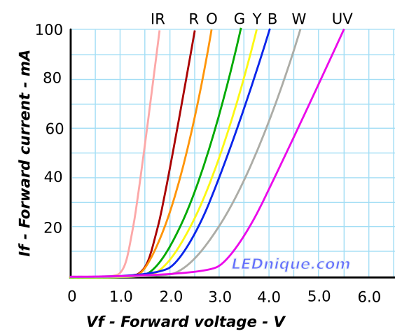
Did you look at the image below I previously posted? Follow the white line, that's for a white LED. Note that the current through the LED at 2.0 volts is maybe a milliamp or two, and at 3.0 volts it's 20 milliamps. By the time you get to 4.0 volts you're over 60 milliamps and the LED is on it's way to LED heaven.
The LED is a non-linear device, it doesn't track with Ohm's Law like adding a resistor as it's replacement.
I'll give you a small bone, it won't have exactly 3 volts across it. However, if you assume it has 3 volts and pick the resistors accordingly, everything will work out just fine. The LED will not limit current (until it blows), it's the resistor that determines the current flow through the LED.
Sorry, I'm not sure the chart proves what you think it does. Let me try to work this out theoretically.
While I fully agree that a diode of any sort, including LEDs and in fact *all* semi-conductors (which after all is why they are called *semi*-conductors!) are non-linear devices, meaning they do not have a fixed resistance and their effective resistance changes as the applied voltage changes, this does not mean they do not have a calculable resistance at any given applied voltage -- Ohm's Law still applies in spades, just not in a nice linear equation. I will return the bone you gave me, and admit I did not change the assumed resistance for the LED in my example when I added the parallel LED (and thus reduced the applied voltage to the LEDs), in part because I did not have your handy chart for the LED under discussion. In fact, your chart gives the key to calculating the effective resistance of the specified LED at any given applied voltage, using Ohm's Law.
For example, for the white LED, when 3 volts is applied, the chart says it will draw a current of about 0.02 amps. To find its effective resistance, dividing the voltage (3) by the current (0.02), which yields an effective resistance of 150 ohms (R = V/I = 3/0.02 = 150) when 3 volts is applied. By contrast, if you apply *six* volts instead, the chart tells us a white LED will draw about 0.09 amps, and the effective resistance can be calculated as 66-2/3 ohms ( 6 volts divided by 0.09 amps). Going in the other direction, if you lowered the applied voltage to 2.5, the chart indicates a white LED will draw only about 0.008 amps, and that works out to an effective resistance of about 312 ohms.
Turning back to the matter at issue, to get a white LED of the type charted to "see" 3 volts from a 12 volt source through a fixed resistor, the needed resistor would have to be three times the calculated resistance of the LED, or 450 ohms. That's remarkably close to the 470 ohms posited in the OP's original question (which was asking if adding a parallel LED was the cause of the resistor overheating and the LEDs dimming, IIRC). For the sake of simplicity, let's assume the chart is reasonably close to accurate for the LEDs in the OP's setup. I'm sure there must be a more elegant way to do this, but as a first approximation, let's assume my 157 ohm calculation for the LEDs is accurate, and that placing two of them in parallel would halve the resistance and reduce the voltage "seen" by the LEDs to about 1.7 volts. But wait -- the chart indicates the LEDs actual effective resistance at that voltage must be higher, since the chart indicates the current running through the LED at 1.7 volts is only 0.002 amps or less, or about 850 ohms! Recalculating at that resistance, the voltage allocated to the LEDs will go up, which will in turn lower their resistance, which in turn will lower the LEDs' portion of the voltage, which will increase the LEDs' current draw and resistance, which will . . . ![]()
I think I begin to see how the LEDs would tend to "buffer" the voltage drop through them, and thus minimize the effect of adding parallel LEDs. In other words, there would be some dimming of the individual LEDs, but the main effect would be the additional power the resistor would have to absorb and dissipate, since the current drawn through it would rise with each added LED. I still think the LEDs would dim a bit and the voltage split "seen" by them would decline some, but because of the LED's non-linear properties, the voltage would tend stabilize much closer to the bend of the chart's "hockey stick" curve than would be the case with a linear device.
I still hope to put together a test lash-up to see what the actual effect of adding parallel LEDs is on the voltage split with a protective resistor, and I'll post the results when I have them.
Are they both the exact same type and color? If there is any difference in the two LED's electrical characteristics, one can starve the second one for power. For instance, if you parallel a red LED and a white LED, the red one will light, and the white one never will.
@Steve Tyler posted:Sorry, I'm not sure the chart proves what you think it does. Let me try to work this out theoretically.
Steve, I've been using LED's since they were created, and I'm pretty sure I have a decent understanding of their characteristics. I won't debate the topic farther, I suggest you actually do some bench tests if you don't believe me.
John, here’s a video of the Z4000 with three trains in the block. The power was brought up to get to 18, and two leaving the block one at a time so you can see the voltage go up.
Attachments
Videos (1)

John, here’s a video with one engine in the block, and two more entering on at a time. Notice the voltage drop.
Attachments
Videos (1)

That is INTERNAL resistance of the supply- aka the transformer. Nothing you can do about it.
Understanding the difference though- internal to a power supply VS external between your load (train) and the transformer is an entirely different story.
Again, and unloaded transformer voltage difference between loaded voltage- both expected and NORMAL.
I'm surprised with the voltage drop, I have reservations about that transformer! I see the current display going from half an amp to one amp, hardly a massive load. There should be a minimal change in the output of the transformer with that light a load.
On my bench, I can put an measured 8 amp load on the Lionel PH180 transformer and I see a voltage drop of slightly less than 2 volts.
Open Circuit Voltage from PH180 Brick

Current into load PH180 Brick

Voltage from PH180 Brick with 8 amp load

Something is very wrong with what I see in that video!
Attachments
Images (3)


While I agree if you never saw one do it, you might say that's a lot of drop but we have 4 Z4000s at the club, some of them the earlier revision and they most definitely do the same thing and there is nothing wrong with them. It's just an apparent voltage vs loaded voltage difference. They are not getting hot, melting terminals, or other typical failure when seen with an actual problem of high resistance connection causing voltage drop.
Cannot stress this enough, a Z4000 when actuated by the handles- does not and will not maintain exactly the same voltage as the load varies. Most any transformer regardless of brand works the same way- most of them just do not have meters digitally displaying the voltage where it becomes obvious.
Just at home tested different recent Z4000 transformers, when set to 18V a the handle with no load, when adding a 3.2 amp resistive load (a 24V rated 3D printer heated bed resistance PCB) the resulting voltage dropped to 13V both displayed on the display and verified using a Fluke 101 meter (meter is not true RMS).
Going from half and amp to an amp should NOT have a 3 volt variation!
@gunrunnerjohn posted:Going from half and amp to an amp should NOT have a 3 volt variation!
Needs repair?
@MCD4x4 posted:Needs repair?
No, it does not. I just tested 2 Z4000 transformers using a 3.2A resistive load and saw it go from 18V set voltage to under load down to 13V.
This is just how they work.
I took video and will post shortly. I am also trying to find a quick 1A load I can plug in and unplug to show loaded VS unloaded.
Video of the first transformer (the one that runs my layout since 2018 every day) https://youtu.be/UUthzvAX9H4
Video was too large for direct upload to the forum.
Video of a second Z4000 showing nearly the exact same results. 18V output unloaded dropped to under 13V measured on the output terminals under 3.2A load.
And, just as another data point, a Z1000 and Zcontroller tested using the same 3.2A load in a loaded VS unloaded output voltage test. Interestingly less voltage drop- however, the output never was 18V full throttle of the Z controller, so the drop is just as much the transformer core itself and then potentially more drop through the control circuit. https://youtu.be/mmcug_fFWr0
That's insane, how can you live with a transformer that does that? If that is normal behavior, it doesn't need repair, it needs replacement! ![]()
FWIW Vern, your test doesn't duplicate what he is seeing, that's more than a 5 amp load you're using, he sees a 3 volt change with a half amp change in current. You can sing all you want "that's how it works", but I say that's a crappy product if that is actually the performance!
My question is that actually the output voltage or just the meters being stupid? It's really hard for me to believe that all the people that use this transformer put up with that performance.
@gunrunnerjohn posted:That's insane, how can you live with a transformer that does that? If that is normal behavior, it doesn't need repair, it needs replacement!
FWIW Vern, your test doesn't duplicate what he is seeing, that's more than a 5 amp load you're using, he sees a 3 volt change with a half amp change in current. You can sing all you want "that's how it works", but I say that's a crappy product if that is actually the performance!
My question is that actually the output voltage or just the meters being stupid? It's really hard for me to believe that all the people that use this transformer put up with that performance.
The club has 4 more of these, I have 3 at the house (that's 7 of these), 1 is still new in the box as my expansion or spare. I know for a fact I saw similar results last night (Thursday night) at train club. This is because I was running a 6-18005 converted to TMCC using ERR AC commander and sounds. With the smoke unit on was drawing about 2A and I saw every bit of a 3V difference between loaded and unloaded when I moved it to a siding and cut the power to the siding.
I also assumed the meters slightly lied, but this testing using the Fluke 101 meter was showing me the measured voltage drop. I thought it was less- often going off incandescent passenger lighting brightness change.
I have to admit, I'm a bit surprised myself, but knowing that in less than 24 hours, I personally put hands on several of these (again, all night Thursday for at least 3+ hours), real loads- somewhere in the ranges of 1.5- to 3 Amps or so, and saw at least 2 maybe 3 volt changes in voltage when going loaded to unloaded and back again through various operations without touching the handle.
@stan2004 posted:Meanwhile, back at the ranch...
So @MCD4x4 are you good to go on your subway LED lighting project?
Stan, I'm ready to hang myself here, way to much information above. Here's what I have currently, power-diode stripe-470-470- positive side of LED.
I've learned the LED's must be the same color. What I'm still unsure of is will this circuit hold if the volts go up to 21 VAC?

Attachments
Images (1)
@MCD4x4 posted:Stan, I'm ready to hang myself here, way to much information above. Here's what I have currently, power-diode stripe-470-470- positive side of LED.
I've learned the LED's must be the same color. What I'm still unsure of is will this circuit hold if the volts go up to 21 VAC?
Using an online resistor calc for 21V input (technically that was DC) 20mA current, 1.81V volt LED (Red)

Notice the LEDs in series not parallel. Yes, because of AC you need the blocking diode.

Attachments
Images (2)


Technically, the math is 21V RMS AC rectified to DC results in a higher peak voltage (1.414X 21V) 29.69V Peak.
Why we use 35V rated DC capacitors in many O gauge circuits.
If you really think you are going to hit 21V AC RMS on a regular basis, then upping to 3 resistors in series, and 2 LED in series might be slightly dimmer but not outside of peak current. As with any advice, testing, your specific condition, might vary slightly. Higher resistance will dim the LEDs more at lower voltages, just trying to account for the max here that would push the circuit.

Attachments
Images (1)


@MCD4x4 posted:Stan, I'm ready to hang myself here, way to much information above. Here's what I have currently, power-diode stripe-470-470- positive side of LED.
I've learned the LED's must be the same color. What I'm still unsure of is will this circuit hold if the volts go up to 21 VAC?
Looks good! I added a few notes for clarification. And yes, it would work fine with 21 VAC. Would be a tad brighter than at 18 VAC though you might not even notice the difference.
Attachments
Images (1)
Remember, you just have to worry about average current, the peak current of any generic LED is at least 50ma as long as the average current is 20ma or less. Also, for parallel LED's, they not only must be the same color, but also the same manufacturer and type. Different brand red LED's, for instance, will be enough different that one will be bright and the other dim. That's why whenever possible I use the series connection, it works with similar and dissimilar LED's.

Well, from what I can tell he's good to go. ![]()
![]()
Come on guys, it was way back in the last century but remember your 2nd-year EE course on semiconductor physics? The same "mechanism" that causes two LEDs in parallel to split current differently will occur with two LEDs in series. In other words just because you force the same current in a series configuration doesn't mean the two LEDs will have the same brightness.
Attachments
Images (1)
@stan2004 posted:Come on guys, it was way back in the last century but remember your 2nd-year EE course on semiconductor physics? The same "mechanism" that causes two LEDs in parallel to split current differently will occur with two LEDs in series.
Well Stan, you're wrong on one point. The current in the LED's will be exactly the same in a series string! ![]() The efficiency of the LED's may indeed figure into the differing brightness, no argument there.
The efficiency of the LED's may indeed figure into the differing brightness, no argument there.
@stan2004 posted:In other words just because you force the same current in a series configuration doesn't mean the two LEDs will have the same brightness.
True, but not because of different currents. ![]()
Perhaps poor grammar or word choice on my part. With the parallel LEDs, the voltage is obviously the same but the currents will split differently based on variations between the two LEDs. With the series LEDs, the current is obviously the same but the voltages will split differently based on variations between the two LEDs. It's the same "mechanism" or underlying physics.
For this hobby application, the OP has a batch of 100 LEDs of the same type and from one package no less. I'd be astonished if one could discern any difference in brightness between any 2 random LEDs from the package whether connected in parallel or series. As I see it, the original question or unresolved issue was resolved by simply clarifying that both LEDs must be of the same type. No math, calculus, abacus, or slide ruler required!
As to how the currents and/or voltage split in a parallel or series configuration, if/how Ohm's Law does or doesn't apply, how a Z-4000 transformer's voltage varies with load current, and so on are interesting discussion points for sure. But I think the matter at hand is to simply get 2 red LED tail lights to turn on together and get the subway back in service for revenue generation. In my opinion of course!
And, in the video, a third(soft white?) led was wired in which was causing the problem. So if he now wanted to add that back in, he would grab power for the white one before the red led resistors and diode, and then place in series the diode and appropriate resistor for the white led, correct?

Attachments
Images (1)
@TedW posted:And, in the video, a third(soft white?) led was wired in which was causing the problem. So if he now wanted to add that back in, he would grab power for the white one before the red led resistors and diode, and then place in series the diode and appropriate resistor for the white led, correct?
Actually, for track power applications, I'd just put them all in series. If you adjust the resistor for the lighting balance you need, you just need two extra parts, the diode and a resistor.
@TedW posted:And, in the video, a third(soft white?) led was wired in which was causing the problem. So if he now wanted to add that back in, he would grab power for the white one before the red led resistors and diode, and then place in series the diode and appropriate resistor for the white led, correct?
One reverse blocking diode is plenty. Don't need to duplicate. All the LEDs can then come in series after this blocking diode. Correct, each LED and corresponding custom adjusted (for that color and brighness) limiting resistor, when putting multiple led sets in parallel. So the red string- 2 leds in series, then dropping resistor, white single led and correct dropping resistor, both strings now in parallel, but the diode is in front of them in series.

Attachments
Images (1)

Series example

Attachments
Images (1)

@gunrunnerjohn posted:Steve, I've been using LED's since they were created, and I'm pretty sure I have a decent understanding of their characteristics. I won't debate the topic farther, I suggest you actually do some bench tests if you don't believe me.
Well, I finally got around to hooking up a test setup, and here's my results:
- First, I was using the Arduino Uno R3 that comes with the Elegoo starter kit to provide 5 volts across a single 330 ohm resistor breadboarded in series with from one to four parallel red LEDs of the sort provided with the kit (they appear identical, but there's no other technical or identifying information otherwise apparent).
- Second, all the LEDs lit, regardless of the number, though as I increased the number of LEDs, each individual LED was slightly but noticeably dimmer. Even with the maximum number I tested (4), the LEDs were IMHO adequately illuminated for most purposes.
- Third, I programed the Arduino to read the voltage across the LED(s), and 'print' the voltage every half second to the serial monitor to give me a visible voltage reading across the LED(s). For some reason, the voltage reads seemed to drift quite a bit, more than the equivalent drift of the supply voltage. For instance, in a minute or so of observation, I saw the supply voltage drift between about 4.67 and 4.74 volts, while the percentage drift on the LEDs (reported below) was much wider. I'm not sure of the source of either drift, but having the LEDs in the circuit seemed to exacerbate the issue, FWIW.
- Finally, here's my observed results. The first column is the number of LEDs wired in parallel (and hooked in series with the current limiting resistor), and the second is the range of readings I observed over a minute or so:
Number of LEDs Voltage Measured
4 2.38 -- 2.53
3 2.51 -- 2.68
2 2.62 -- 2.75
1 2.63 -- 2.97
So, it does appear that the LEDs do in fact dynamically resist "losing" voltage to other, fixed resistance, components (in this case, the 330 ohm current limiting resistor) as more are added in parallel. The relatively slight voltage drop observed with an increasing number of LEDs is consistent with the observed slight dimming, and there was no noticeable (to the touch) heating of the very small resistor, which at a guess is only rated at an eighth of a watt or so.
So to conclude, I agree with John that additional identical LEDs added in parallel will still attempt to "see" a collective voltage drop of approximately 3 volts. I'm assuming they will split the total current (which should only increase slightly) amongst their number, again assuming they have identical characteristics, and with any number of them in parallel, each will light up with approximately the same brightness as the others -- at least, I observed no noticeable variation among them. I'd also guess the load on the resistor (the wattage it would have to dissipate) would also only increase slightly. I still think an individual resistor for each LED is the way to go, but it would appear there's no conceptual reason why you couldn't feed a parallel group of identical LEDs through a single resistor (though in light of the slight voltage drop, it might make sense to slightly lower the resistance of the resistor, to offset the observed dimming), with little danger of overheating that resistor unless the LEDs are unusually high draw. Of course, as others have reported, different types of LEDs do *not* like to play together, in series *or* parallel, so caveat emptor!
Any thoughts/corrections to any of this?
Sounds pretty close to me.
I use current regulators in TO-92 packages along with a diode. Then I can run on any track voltage, command or conventional.
You can see them on eBay auction number 163898920883
@RoyBoy posted:I use current regulators in TO-92 packages along with a diode. Then I can run on any track voltage, command or conventional.
You can see them on eBay auction number 163898920883
A buck apiece for each LED or two cents for the resistor and diode. If you do a lot of them, this is an easy choice. ![]()
You also glossed over the fact that you have to have a diode and filter cap for the CL2 to function properly.
Concerning the Z4000 voltage reading issue, I have noticed the same at our club layout. We have four Z-4000s. When I clean a track, it is easier for me to just use the handle. I found that 11 volts on the display was just right for cleaning track (using one Williams engine and one track cleaning car). I would preset 11 volts on the display then flip the toggle switch to power the track. Immediately after, the display would read 8 to 9 volts which was too slow. Then I would bump up the handle until I got to 11 volts and the engine would run at the desired speed.
After I figured this out, I would preset the voltage to 14 and when I flipped the switch the display would drop to 11 and the engine would run at the correct speed.
I agree that this is odd behavior, but I guess what I'm trying to say here is that I'm glad it seems to be a common problem with the Z4000 rather than a problem with our layout.
Add Reply
Sign In To Reply
