@rplst8 posted:

Litigation?  For what - converting bytes from one thing to another?  AFAIK all the DCS patents should have expired by now, and I'm sure Lionel would welcome an ability to run MTH locos with their remote - not having spent a dime on R&D.  Legacy remotes will be flying off the shelves.

Legacy has been out since around 2007 when the patents were still in play.  This is when Dr. ZW was working in the lab late one night. ( did you get that song stuck in your head?)

As far as Lionel welcoming the ability to run DCS engines, I'm sure they really don't care either way.  With MTH being able to run Legacy engines, Lionel probably sold extra Legacy bases, required for MTH to run Legacy, and engines so I suspect they were probably OK with that.

Last edited by MartyE

Lionel would much rather sell Legacy locomotives than arrange for you to be able to run DCS locomotives with the Legacy system.  Truthfully, while the user community might like it, I don't see any upside for Lionel to spend the R&D money to make this happen.

I suspect the Legacy Command System is not the most profitable product in the stable.  The fact that they have continued to repair them under an extended warranty should tell you what you need to know.  You won't be buying lots of Legacy locomotives if you don't have a command system to run them with!

It’s not all that different from companies that sell printers at a loss to sell you ink at a huge markup.

That said, if Lionel can afford to offer an extended warranty for free, that tells me they can afford to do it, or can’t afford not to.  Either way, I doubt they would thumb their noses at any increased sales of one of their SKUs.

Think about it this way, a current DCS-only, remote loving operator will soon have no way to replace their remote if it breaks or the remote-compatible.  If someone else releases a cheap, or free to custom make Legacy-DCS bridge, the the Legacy remote and command base become an option for them.  Also, that person may then be more inclined to buy more Legacy locomotives as well.

@rplst8 posted:
Think about it this way, a current DCS-only, remote loving operator will soon have no way to replace their remote if it breaks or the remote-compatible.  If someone else releases a cheap, or free to custom make Legacy-DCS bridge, the the Legacy remote and command base become an option for them.  Also, that person may then be more inclined to buy more Legacy locomotives as well.

Well, you can think of it that way, but I'll bet it'll be a cold day down below before you see a Legacy-DCS bridge product from Lionel.

If such a product happens, it'll be a 3rd party that produces it.  I still believe that Lionel has no interest in making it easier for people to run DCS products, it's just not in their financial interest.  Since as near as I can tell, the bean counters run the show at Lionel, something that doesn't positively impact the bottom line has little chance of success.

Hi Professor Chaos,

When I power on the bridge with the USB cable I get this on the Serial Monitor

Command Monitor starting

PDI Interface initialized

RFM69HCW radio init OK

This repeats when I plug in the PDI cable.

I am in Legacy mode now on engine id 4.  (I was also with engine id 58)

I do Front and then Rear Coupler commands and nothing appears on the Serial Monitor.

I build a test jig with a spare PDI PCB board to look at the PDI signal on pin 13 of the MAX3232 with an oscilloscope.

When I do Front and Rear Coupler commands I see a -9V to +9V signal on pin 13.

I detach the PDI board and apply 3.3V to proper pins on the PCB, insert the PDI cable, and look at the signal on pin 12 of the MAX3232 with an oscilloscope.

When I do Front and Rear Coupler commands I see no output on pin 12 of the MAX3232.

I built another PDI/MAX3232 board incase I have a bad component.  I am using you through-pin version of the board.

I still don't get a signal.  I checked the traces on the PCB with an Ohm meter and they looked good.

I am probably making a simple mistake but I can not see right now.

Tomorrow, I will bread board a MAX3232 to test.

PDI/MAX3232 board picture

PDI Board

Attachments

Images (1)
  • PDI Board

Hmm, can't see anything obviously wrong.  Breadboarding with a MAX3232 would definitely be the next step. I use an ADM3202ANZ instead of a MAX3232.  The ADM is specced at a higher data rate than the MAX3232, but you should still see a signal.

Do you have the Legacy DB-9 PDI cable plugged directly into the bridge, or do you attach the bridge to another LCS device? I attach mine to the end of the LCS chain (in my case, two SER2 modules).  

I have a vague memory of having trouble when I plugged the bridge directly into the Legacy base.... so if you have an LCS module, try connecting the bridge to the extra PDI port on the module rather than the Legacy DB9-PDI cable.

@carl552 posted:

I attach the bridge directly into the Legacy DB-9 PDI cable.  I don't have any LCS devices to add.

I'm guessing that's the problem.

I know the Legacy base sends out a "who's there" packet over the PDI bus when it's powered up, and periodically sends out a ping packet. It could be that if the base doesn't get a response to at least one of those, it assumes there's nothing on the PDI bus and doesn't pass TMCC commands out on the bus. The demo sketch is not programmed to respond to inquiries from the base.

Possible solutions could be:

- get a LCS device

- forget the PDI bus, and read 'old-style' TMCC serial commands out of the base DB9 port at 9600 baud. This is a more complicated because you need to find another power supply for the bridge, and not short the TMCC earth ground to layout common (outside rail). I have done that by powering a bridge with the layout accessory supply and optically isolating the serial connection to the base, but it could also be done with a separate wall-wart not connected to layout common.

- I could attempt to add code to the demo sketch so that it behaves like a proper LCS device and announces its presence to the base. If I'm right about the problem, that would resolve it.

When I measured the output of pin 12 there was operator error.  When I did the breadboard I found that the MAX3232 seems to start missing packets below 3.3V.  I must have not turned my power supply up high enough.  I put the bridge together and made sure 3.3 V was getting to the MAX3232.  I was now getting the 3.3V logic signals from the MAX3232 on pin 10 (RX1) on the Moteino Mega.  The serial monitor still showed no activity.  I started reading the sketch and decided to try TMCCSerialClass on the serial monitor instead of the PDIClass.  Now I see the commands on the serial monitor.  An example is Rear Uncouple

Received TMCC command FE ID 6

Command state 1

Device 0

Address 58

Command 0

Data 6

Bit9 255

I fired up the PS2 engine ID 58 in idle and tried the uncouple commands that did not work.

At least I am now seeing activity on the Serial Monitor. 

Sorry for the low voltage dead end.

Hi Carl -

I'm a little confused. You state that you tried instantiating the TMCCSerialClass monitor instead of the PDIClass monitor. There is no way that should work if you are still connecting via the PDI bus - are you now connecting a 9600 baud serial connection via the  Command Base DB9 port?

Anyways, you have it working somehow, since the output shows that the Moteino is parsing a command for engine 58. But your output shows a TMCC command (FE xx xx) not a Legacy command (F8 xx xx). The demo code responds only to Legacy engine commands, although it would be very easy to modify it respond to TMCC commands as well.

So, set the control type of engine 58 in your Cab-2 to "LEG".  Here is the output I see when I start the program and send a rear coupler command to Legacy engine 58:

Command Monitor starting
PDI interface initialized
RFM69HCW radio init OK!
Received TMCC command: F8 75 6
Command state 2
Device 248
Address 58
Command 6
Data 40
Bit9 1
TX_ON
Writing:55556A666696656655555A596A5A599A4D
55 55 4D 6A 95 A9 55 5A 59 55 55 - Remote # : 14 - Count : 11 - ACK


This indicates that a command was received for engine 58, was converted to a DCS command, sent out the radio, and that we received an acknowledgement from the TIU.

Last edited by Professor Chaos

Incredible!!!!! IT Works.  Thank You Professor Chaos.

Another mistake, I assumed that when the controller did not say CAB-1 and displayed the engine info it was in Legacy mode.

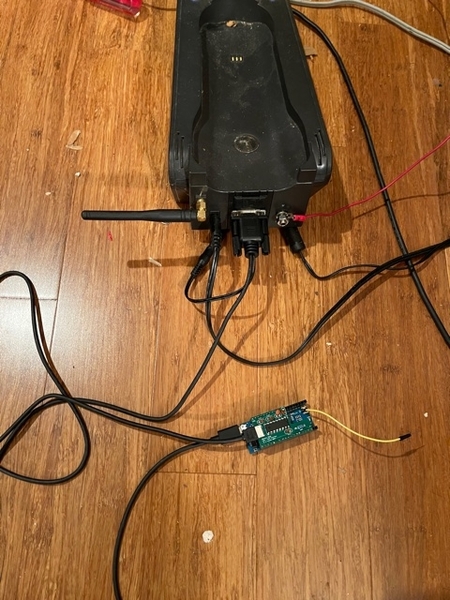
I still think it is connected to the PDI bus.  A picture of my setup with the Lionel Serial to PDI adaptor connected to the Legacy base serial connector and the PDI connector of the Legacy-DCS Bridge.  I am getting the correct serial monitor output with the TMCCSerialClass.

IMG_1261 [2)

Attachments

Images (1)
  • IMG_1261 (2)

Glad you got it to work!

I still think you must be compiling with the PDI class - does your monitor really say "TMCC Serial interface initialized" instead of "PDI interface initialized"?  Just for kicks I tried to compile with the TMCCSerial class, and as expected received gibberish from the PDI interface.

At any rate, feel free to now extend the demo to translate more useful commands!  You would need to reference the Lionel Legacy documentation and Mark's documentation of DCS commands on the Silogic website.

I really appreciate all of the effort that folks are putting into this endeavor, and am grateful for everyone's willingness to share the details.  Thank you!

I'm impressed by the technical genius.  But what I'm really jealous of is the fact that several folks have the time and mental energy to devote so much effort to the task, many of whom might be holding down a full-time job.  I can barely find the time to run trains or build scenery...

Keep it up, guys!

Last edited by Mallard4468

Carl, it turns out you are correct!  I just tested and discovered something fascinating and undocumented about the Legacy base.

When no LCS devices are connected, the Legacy base reverts to the "old-fashioned" 9600 baud 3-byte TMCC protocol even over the PDI bus. That is why you succeeded when you compiled with the TMCCSerial class.

I assumed that when the DB9-PDI adaptor is connected, the Base would always be communicating (if at all) on the PDI bus using the 115200 baud LCS packet protocol.  Nope.

This also explains why I was not able to get the bridge to work when I connected it directly to the Base PDI plug, rather than at the end of a LCS device chain - I was trying to talk to the base with the LCS protocol, but the absence of LCS devices reverted the base to the old serial protocol.

Last edited by Professor Chaos

Another use for Professor Chaos’ Legacy-DCS Bridge is to allow JMRI and Train Controller to communicate with DCS engines.  This post describes the progress in making that happen.  I had multiple emails with Dave Hikel discussing computer controlled trains. (Dave was very generous with his discussions with me)   My original plan was to use Train Controller Gold and purchase Dave’s hardware/software to control DCS engines from JMRI or Train Controller.  I sent Dave the IP addresses to the DCS wifi units that were required.  Unfortunately, I have not heard from Dave since I sent the information early this year.  (I pray that Dave is well.)  In July I decided I needed to read Professor Chaos’ Legacy-DCS Bridge post more closely.  I did not want to learn C++ , learn and edit the bridge program but I might not have any other options.  I built the bridge hardware and with the help of Professor Chaos was able to demonstrate the hardware and software working properly.  The DCS commands I want Train Controller Gold to operate autonomously are: Speed, Forward, Reverse, Start Up, Shut Down, Smoke On, Smoke Off, Front Coupler, Rear Coupler, Horn/Whistle On, Horn/Whistle Off, Bell On and Bell Off.  I received a very helpful email from Mark DiVecchio on the DCS Start Up command sequence. 

The Legacy base can only receive TMCC1 commands at the serial port.  Train Controller also outputs only TMCC1 commands.  After learning a minimum amount of C++ I skimmed Professor Chaos’ program and found the places in the code that I needed to edit.  Professor Chaos made it straightforward to change from Legacy to TMCC1 commands and add more commands to the program.  I have demonstrated my list of commands on a PS2 engine with both a Legacy controller and Train Controller using a serial Y connector.  There are still improvements to be made for usability and automation.  My Train Controller DCS demonstration was done with only the DCS Bridge on the PDI bus.  When I added the LCS WiFi unit to the PDI bus the Train Controller was no longer able to communicate with the DCS Bridge.  The LCS documentation shows a CAB1 base and the PDI bus joined by a serial Y connector communicating with the Legacy base.  I had hoped I could replace the CAB1 base with the Train Controller.  Any suggestions to get around the problem would be appreciated. I need to add comments to the code and then I will post it.  Again my additions are small compared to the work of Mark DiVecchio and Professor Chaos.

Hi Carl - if I'm reading your last post correctly, you connected a LCS device (WiFi) to the Legacy PDI bus, where previously you had only the Bridge connected. Then the Bridge would no longer receive commands.

Did you change the instantiation of the Monitor class from TMCCClass back to PDIClass? I have not tried a WiFi module, but (as described in my last post) when I connected a SER2 module, the Base changed itself from 9600 baud TMCC communication to 115200 baud LCS packet communication. Hopefully the same is true when a WiFi module is connected.

I have not tried injecting serial commands using the Y-cable with PDI devices connected; I use a SER2 module. According to Lionel this is the only way to send TMCC2 (Legacy) commands into the Command Base.

From the Lionel documentation it looks like you should be able to swap the CAB1 base for a computer using the Y-cable, but the Base must be doing some magic to simultaneously accept 9600 baud TMCC commands from the CAB-1 end of the Y-cable and 115200 baud LCS commands from the PDI end.

Interesting work here. Last winter, I had started work on a command control system.  But instead of attempting to control engines from DCS to Legacy or Legacy to DCS, I decided to control engines from an outside system that would communicate with the TIU or Legacy base as needed.  I had also started developing my own command control system and was working on expanding my low level MCU library to communicate with the various chipsets via I2C when I had to switch gears to the outside world.

Anthony

Hi Professor Chaos,

Just back from York and the SER2 was finally delivered by the USPS.  Connecting the PC running Train Controller to the SER2 module and the DCS Bridges works well.  Now I am able to control TMCC/Legacy and DCS trains 3 ways, from their original remote, WIFI remote app and computers with Train Controller or JMRI.  Plus DCS trains with the Legacy remote.  You and Mark DiVecchio did great work.

Carl

Add Reply

Post
The DCS Forum is sponsored by

OGR Publishing, Inc., 1310 Eastside Centre Ct, Suite 6, Mountain Home, AR 72653
800-980-OGRR (6477)
www.ogaugerr.com

×
×
×
×
Link copied to your clipboard.
×
×