Hello'


I had the body off of my MTH 3GS21B diesel (Item# 20-20003-1) when I put it back on the front ditch lights did not work.  I tested the voltage at the contacts and I had power.  After looking at it I found that the spring where not contacting the contact plate.  I tried to re-position the contact plate.  When I placed the body back on I saw a puff of smoke come from the middle of the engine.  Now I don't have any lights and both couplers make the sound like they are opening, but do not open.  All sound functions work and the engine moves forward and backwards.  Are the couplers and lights somehow combined on the same circuit?  Any help would greatly be appreciated.


Thank-you

Original Post

Replies sorted oldest to newest

Yes, the coupler and lights are on the same circuit in that there is a common voltage (called "PV") that connects to 1 side of each light and each coupler.  This PV voltage comes out of the #2 contact of the 10-contact connector and is distributed throughout the chassis/harness; it is usually purple wires.  The MTH PS2 diesel upgrade kit instructions:


http://www.mthtrains.com/sites...ction/50as15442i.pdf


has the following hard-to-read diagram.
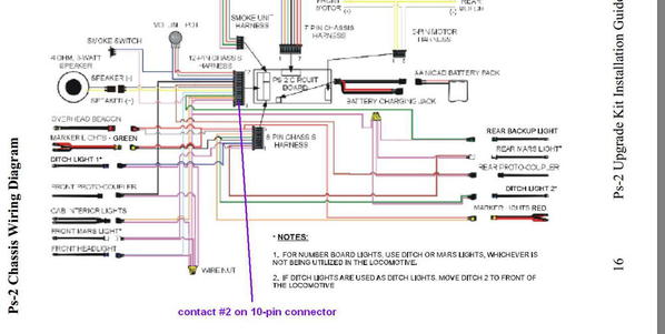
 

ogr ps2 diesel wiring

That PV voltage is also used to power the motors and the smoke unit.  Does smoke still work?


Since the motors still work, I'd guess the PV voltage itself is OK but is not making it to the purple wires out of contact #2.  And if I were to make a guess, that puff of smoke was something akin to a fuse going up in smoke from excessive current.  So even if you find the weak-link so to speak (such as some BBQ residue on the board or on the connector) you need to find the cause.  When you were messing with the ditch contacts perhaps you introduced a short to the chassis/frame?


While things are crammed in there, it should be relatively easy to pull the 10-pin connector straight up from the housing on the board.  This can give you better access for visual inspection and/or to make continuity measurements using a meter.  For example, you should see no continuity between the contact #2 purple wires and the frame/chassis.

Attachments

Images (1)
  • ogr ps2 diesel wiring

I just had this problem on a diesel. I tested the light with a battery and it worked. So I bent the spring out a bit with a screwdriver, as GGG posted. It made the difference and the light came on when the shell was screwed on tight.

 Make triple sure no wires get in between the shell and frame to cause a gap.

of course that doesn't fix the coupler.

Last edited by Engineer-Joe

No power goes IN to the 12-pin connector per se.  They are all outputs (to lights, couplers, speaker).  These output signals come from the board itself.


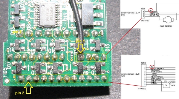
If everything else works (motors, smoke, sound) but couplers and lights don't, I don't think you are getting PV at pin 2.  If you have steady hands and your meter's probes aren't too "fat", probe the contacts on the 12-pin connector as shown.  Measure DC-voltage between pin-10 (circuit ground) and pin-2 (the elusive PV voltage).  With the engine powered, the measured DC voltage will be about the track voltage plus or minus.  Both of the contacts usually have more than 1 wire coming out so it can be tricky to access metal of the crimped contacts with the probe tips.


ogr measuring ps2 PV voltage

Attachments

Images (1)
  • ogr measuring ps2 PV voltage

Can you pull the 12-pin harness/connector straight up out of the housing to expose the male pins?  I just grab the entire bundle of 15 or so wires and pull up maybe with a little wiggling.


Then, inspect the both sides of the pin 2 (what's on the board and what in the harness) for anything odd looking.  Then with power applied, carefully probe between the now exposed male pins 10 and 2 to see if you get a DC voltage.  In other words, we're working backwards toward the source of PV.


Obviously you'll have no sound since the 2 speaker wires came out.


Edit: picture added.  This is obviously an un-powered loose board on the bench but was what I needed to do to take photo with camera in one hand, etc. etc.


ogr pv in housing

Attachments

Images (1)
  • ogr pv in housing
Last edited by stan2004

Just to confirm, you are getting smoke?  Not just the smoke fan whirring, but actual smoke coming out?


The next step is to carefully inspect around pin 2 and the housing.  Here's an example of a blown PV printed-wire from a repair I did.  I'm not saying this is the only place to look but what it might look like.  In this case the failure was hidden in the gap between the 12-pin housing and the 4 and 8 housings next to it.  You'll know it when you see it!


ogr example of ps2-3v-blown-pcb-PV-trace


If you are not getting PV at pin 2, then I'd say you're going to have to remove the board set from the engine.  I suppose you need to start thinking about sending it to one the MTH techs if this is getting too involved.


Separately, I still believe you need to track down what I believe must be a short in the harness that took out PV.   With the 12-pin harness pulled, did you 'ohm-out' the contact #2 at the connector to the engine frame/chassis?


Attachments

Images (1)
  • ogr example of ps2-3v-blown-pcb-PV-trace
@stan2004 posted:

Just to confirm, you are getting smoke?  Not just the smoke fan whirring, but actual smoke coming out?


The next step is to carefully inspect around pin 2 and the housing.  Here's an example of a blown PV printed-wire from a repair I did.  I'm not saying this is the only place to look but what it might look like.  In this case the failure was hidden in the gap between the 12-pin housing and the 4 and 8 housings next to it.  You'll know it when you see it!


ogr example of ps2-3v-blown-pcb-PV-trace


If you are not getting PV at pin 2, then I'd say you're going to have to remove the board set from the engine.  I suppose you need to start thinking about sending it to one the MTH techs if this is getting too involved.


Separately, I still believe you need to track down what I believe must be a short in the harness that took out PV.   With the 12-pin harness pulled, did you 'ohm-out' the contact #2 at the connector to the engine frame/chassis?


Hey Team,

Sorry to revive a really old one here. Tonight, I'm almost positive I had a coupler short out, and I got myself into a BBQ at 11pm. Turns out, I inspected the board, and the image that is shown is exactly what happened to my board set. PS2 3V.

The question: How in the world do you get in and repair that trace? Do you jumper it from the bottom of the board?

-Ben

There are two ways.

One is to warm up the plastic connector shell with a heatgun and gently remove it, then you can patch the trace with a small piece of wire, I use #30 Kynar wirewrap wire.

The other way is to take a working PS/2 board and hunt down the two ends of the wire, one being the pin and the other being the source of PV on the board.  Jumper between those two points to achieve the same result.

ps2 3v processor board bottom side 12-pin connector

Referring to the PS2-3V wiring diagram GRJ posted earlier, the "PV" signal on pin 2 of the 12-pin connector is also on pin 1 of the 4-pin smoke connector.

I'd first use a meter to confirm the (lack of) continuity between the 2 points.  That's close-quarters soldering so double and triple check your handiwork for unintended solder bridges or what have you...

Attachments

Images (1)
  • ps2 3v processor board bottom side 12-pin connector

Add Reply

Post

OGR Publishing, Inc., 1310 Eastside Centre Ct, Suite 6, Mountain Home, AR 72653
800-980-OGRR (6477)
www.ogaugerr.com

×
×
×
×
Link copied to your clipboard.
×
×