Hello internet train friends! The things presented here will be from my experiences, meant for people who are new to these. YMMV. Please kindly add things I may have forgot.
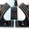
Many people know about the 1121 O27 switch. The very pretty art deco styling of the bakelite solenoid housing and controller is pleasing to the eyes in the sea of brown and black pads with random lumps and bumps on them. Here I'm going to show a few things that may help and hopefully increase your enjoyment of this classic switch.
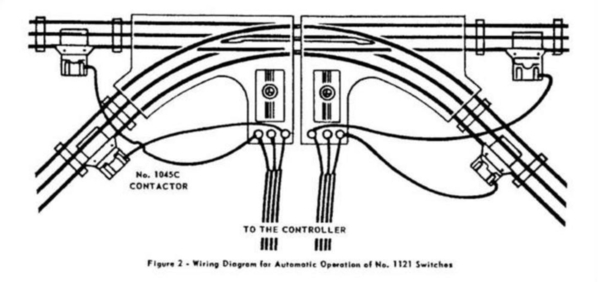
ANTI-DERAIL - These switches do not have this feature like the later ones did and there are a few ways to simply accomplish this. Using insulating pins and separate straight pieces of track is most likely the easiest. Attached below is the schematic from the service manual for this switch, displaying how to! You could also substitute the Lok-on pieces with soldered wire for a cleaner installation. The basic premis is that when the locomotive completes the common rail circuit, the solenoid will snap the switch in that direction.
CONSTANT VOLTAGE - These switches are set up to be run from track voltage. This may cause the solenoid to move slowly, incorrectly throw the switch or not work at all depending on the voltage. Attached is the wiring diagram. Follow the middle rail up. The important wire is hilighted with a red arrow and in my experience has had black cloth insulation. Desolder this wire from this point (easy to notice as the wire is the only one that goes out to the tracks) and route it back through the base to provide a link for constant accessory voltage.
BULBS - The bulb inside the 'motor' housing is partially hidden by a slider, allowing it to shine through the corresponding direction indicator, red or green. These bulbs get very hot on constant voltage and you may want to replace them with LED's. The bayonet style (after 1950) base is a BA9S and the socket style (before 1950) is an E10.
REMOTE CONTROL - The control box for this switch is a piece of art but sadly, lacks the cordage to get very far (most of my controllers only have 24" of cord on them or less). I used speaker wire for this (sorry GRJ) and the idea is to extend the connection posts that are on the side of the 'motor' housing to underneath. In this picture you'll also see the accessory voltage wire mentioned above. Lionel provided a nice little rectangular access hole on the bottom cover of the switch body to route wires through too! All you have to do is solder one wire to the left post and the other to the right. These also have the coil common wires soldered to them. You can run the two wires to a remote DPST momentary switch, then run the other side of it to common which is effectively what the control box is doing, except any common will work.
COIL REPAIR - I will admit, I did a stupid thing by drilling too close to the coil packs that control the switch. She got away from me and ended up damaging the outer two layers of windings. I'M NOT AN ELECTRICIAN OR ENGINEER and frankly, anything more than 240v scares me. All I know about the two coils (no math, please) is that when the circuit is completed one way or the other, they make an electromagnet that pulls a plunger out or in. I was able to save the coil I screwed up and retaped and resoldered it back to where it belonged. However new (or NOS or used) ones are available on TheBay or Trainz.com or traindoctor.com - it's ludicrous that the $3 part for me was subject to $30 shipping. I only changed the resistance by .25 ohms and that's good enough for me. The whole assembly is just attached to the baseplate with 4 tabs and the two coils just slipped off the tube. If you have to remove one just take your time.
That's really it. There's nothing else really going on here. These switches do accommodate the Marx 'fat wheel' single reduction motors and are just as reliable as the rest when you add the non derail feature to them. Hopefully this helps! (psst... I'll attach the service manual too).
Happy trains!


