This piece came in today with a million issues. Drive gear block frozen (tan grease). —Fixed

Cracked dog bone. —Replaced

Bad fan motor. —Replaced

Loose old wires and bad solders everywhere. —Fixed

Loose boards and inner frame. Fixed.

This was serviced once (or so they said) by Lionel in 2009 after the customer bought it in 2008. He never ran it again after having run it a few times post 2009 service (or so we were told).

Found all of the above when I opened it and the fan motor was drenched in fluid. No life.

Everything is now back to factory and running smooth with one alarming problem - The puffing fan effect is malfunctioning. I only get one puff when I bring her to a stop. While moving, I hear chuffing, I hear the cherry switch clicking 4 times per rev, but get fan pulse to go with it. Heater is doing its job well.

So which board and/or board triac or other component has failed?

Is the bad part available or is it time for a custom workaround and/or GRJ’s Superchuffer??

Thanks for everyone who has chimed in recently on other questions with help. Really appreciate you guys!

Attachments

Videos (1)
trim.3D1F3C18-135D-41B8-8EC3-3EE01AEC9069
Last edited by DdotCdot
Original Post

Replies sorted oldest to newest

It's interesting that it has an analog smoke unit and no output for fan control.  Truthfully, I don't see how this particular model controls the smoke fan.

I have a special version of my Super-Chuffer II for early Legacy locomotives, I put one in my Legacy C&O 10-wheeler from the same timeframe.  My 10-wheeler had a special fan control board that managed the fan, it just did it poorly.

I think I'd have to see that one to figure out what was driving the smoke fan chuff.

There's no mystery where the chuff signal comes from, but other early Legacy locomotives had a smoke fan controller board to manage the smoke motor.  I don't have that particular smoke unit in stock, so I can't see if it has the microprocessor on it, typically they call those a "smart" smoke unit.

This is what I was expecting to find with an analog smoke unit.

Attachments

Images (1)
  • mceclip0
@GGG posted:

The picture on the web show similar components though you can't see all of them, and the integrated harness indicates a separate drive wire for the fan.  Hence my call that it does have a system.  It really is hard to believe Lionel could not come to one simple system to generate puff with chuff.  G

Some of us have used the simplest and most obvious solution, just use two micro switches on the cam. One for chuff and the other to the fan motor. About as simple as it gets and no added circuitry required.

Pete

John, this was simply a reply to George who like me and many others are miffed that Lionel couldn’t find simple low cost solution. Two micro switches wholesale for 50 cents. I am not aware of any other solution that is even remotely close to that price.

Two switches and 4 lobe cam. No smart regulators, no semi smart regulators, no micro controllers counting motor tach pulses. Zero, zip, nada. K.I.S.S.  Lionel could have done the same thing.

Pete

Attachments

Videos (1)
IMG_0165
Last edited by Norton

My beef with micro switches is they put enough drag on the locomotives motor that at low speeds often you can see the locomotive surge with each revolution of the wheel.  On my early conversions to TMCC I used a reed switch and magnets to switch a 3v DPDT relay one pole for fan one pole for chuff. Later I switched to an optical reader and four dots of white paint ,or white tape, on the inside of the drive wheel. The size of the white dot determines the length of the chuff/ puff.  It's my "Not So Super Chuffer" but works flawless and is quite simple.          j

@JohnActon posted:

My beef with micro switches is they put enough drag on the locomotives motor that at low speeds often you can see the locomotive surge with each revolution of the wheel.  On my early conversions to TMCC I used a reed switch and magnets to switch a 3v DPDT relay one pole for fan one pole for chuff. Later I switched to an optical reader and four dots of white paint ,or white tape, on the inside of the drive wheel. The size of the white dot determines the length of the chuff/ puff.  It's my "Not So Super Chuffer" but works flawless and is quite simple.          j

What optical reader do you use and where do you get it?? This sounds cost effective and doable. Thanks!

So far I have only done one engine with two micro switches. Usually I use a single micro switch driving a DPDT reed relay to split the signals between chuff and fan motor. Space in the frame for a wider cam determines if two switches will work. I have also done a few engines with optical detection. First used round dots, the second lines as I wanted the fan on time to be short. All upgrades were done with Pittman motor engines. Switch drag is imperceptible. With optical devices the circuit is trivial but it takes time to fabricate a mount for the detector.

Pete

Last edited by Norton

Spoke with Mike Reagan on the phone. He suggested checking continuity between pin #24 (or the one completely opposite of the square soldered pin) on the R4LC and the white or black wires running to the smoke unit PCB (wires #3: black or #4: white) next to the AC in. He was going entirely off memory with me over the phone so I wasn’t expecting an bingo answer to the situation, but he did prove was a break in continuity between those two points.


I got no continuity either way. I tried jumping a wire from #24 to the white wire on the smoke PCB and here is what happened:

While in motion - 4 chuffs sound turned into 1 chuff per rev, smoke unit fan began spinning constantly.

So perhaps this suggests there is a break in the proper wire flow somewhere that leads to another board first, but jumping straight from pin 24 to the smoke unit PCB does not solve the problem, it does however prove a break in continuity somewhere in the original schematic.

He didn’t think the PCB on the smoker was bad, and it doesn’t look or smell bad, but I don’t know enough about this board to know for sure.

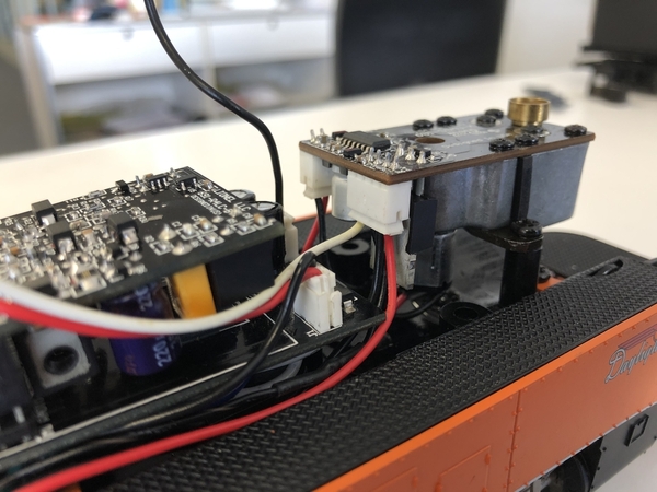
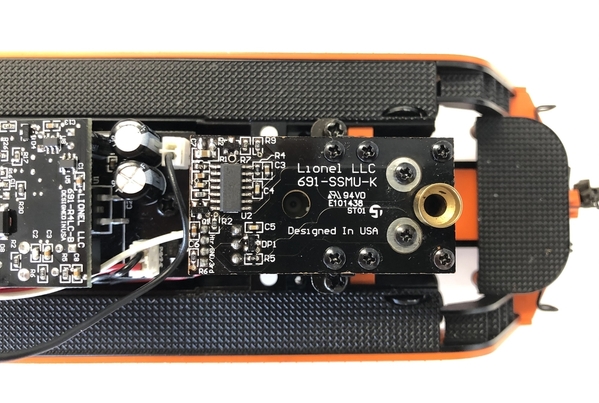
How about some pictures of the PCB and what chips are on the board.  It sounds like it has the chuff circuit on the smoke unit if it's getting serial data.

@Norton posted:

John, this was simply a reply to George who like me and many others are miffed that Lionel couldn’t find simple low cost solution. Two micro switches wholesale for 50 cents. I am not aware of any other solution that is even remotely close to that price.

Two switches and 4 lobe cam. No smart regulators, no semi smart regulators, no micro controllers counting motor tach pulses. Zero, zip, nada. K.I.S.S.  Lionel could have done the same thing.

Certainly true, 3rd Rail managed to use two microswitches, though they used them for switchable chuff rates.  I don't know why they didn't always have a 4-lobe cam, that was a mystery.

The killer was, in my early Legacy 10-wheeler, they used that  smoke logic board, surely that was more expensive.

How about some pictures of the PCB and what chips are on the board.  It sounds like it has the chuff circuit on the smoke unit if it's getting serial data.

Certainly true, 3rd Rail managed to use two microswitches, though they used them for switchable chuff rates.  I don't know why they didn't always have a 4-lobe cam, that was a mystery.

The killer was, in my early Legacy 10-wheeler, they used that  smoke logic board, surely that was more expensive.

Best I could take.

Attachments

Images (7)
  • D71FF59D-0A4A-43E1-A89A-44265FE2EDCD
  • 17EFD797-584D-4083-AAAB-94760986B45B
  • 4013D950-C3A8-4E1B-B01F-0607F3E86B73
  • 28F02B07-E34B-4569-B86F-76CD23A171B9
  • 5793B44F-B3A2-43FC-9D89-D2812B2B1453
  • 8697BEC0-0071-4268-B72A-375A1CCE05C9
  • 4743DFF8-4047-4D6D-A6E7-EEE589B1400D

just found this thread....

https://ogrforum.ogaugerr.com/...c-big-boy-smoke-unit

it’s making me think I need to crack her open again and investigate the white wires at the cherry switch, as much as I dread opening the lower chassis of this monster again. It’s a nightmare the way the boards and wires are strung through. More updates later tomorrow. Need to step away for today.

Last edited by DdotCdot

I can't see why you'd dig into the chuff switch.  If the chuff sound is right, the switch is working.

I'm saying that the parts listing description doesn't match what is actually in the locomotive.   Actually, the fan control stuff is apparently needed for this particular model as there's nothing else to control the fan.

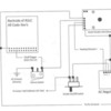
Since this smoke unit has four pins, my guess is the white wire goes to the chuff switch and not to serial data.  Here's a wiring diagram of a similar vintage locomotive with that smoke unit.  Looks to me that smoke unit doesn't take in serial data, but rather the output of the chuff switch.

7123LegacyBigBoyLocomotiveWiringDiagram

Attachments

Images (1)
  • 7123LegacyBigBoyLocomotiveWiringDiagram
Last edited by gunrunnerjohn

Add Reply

Post

OGR Publishing, Inc., 1310 Eastside Centre Ct, Suite 6, Mountain Home, AR 72653
800-980-OGRR (6477)
www.ogaugerr.com

×
×
×
×
Link copied to your clipboard.
×
×