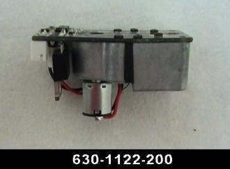
I hate to ask a dumb question, but I would like to bench test this smoke unit that I found in a box of junk parts at York, but I don't know exactly how to do so. I tested the fan using a partially depleted 9 volt battery and it ran fine. I'm just not sure about the white 4-pin receptacle on the board.

The printed side says “Htr/GRND/3rd", but what is the 4th pin for? Is it as simple as connecting the hot lead from my transformer to the “Htr” and “3rd" pins and the ground lead to the “GRND” pin?

Thanks for the help!  

Dean


pic01pic02

Attachments

Images (2)
  • pic01
  • pic02
Original Post

Replies sorted oldest to newest

The silk screen on the top of the connector shows HTR/GND/3rd Rail. From what I can remember the 4th pin (closest to the center of the PCB (opposite 3rd) is serial data from the R2LC. 

So, from the square pin you have 3rd rail (center rail collector, 18V), GND (chassis ground), HTR (this is the element lead from an AC Regulator (likely a 691ACRGE01) which itself has 5 wire connections we'll get into next), Serial (pin 24 from the R2LC).

(the fan motor will be on even when the heating element is off (hence 3rd rail and ground, constant power) the fan motor pulses based on chuff commands on the serial line. The fan motor will not run in idle or neutral. This is how the unit puffs in sync with the chuffing.

The AC Reg, it has 5 connections (again marked on opposite side of where the wires go): 3rd rail, chassis ground, heating element hot, element ground (no need to connect this lead), serial (pin 24 on the R2LC). The AC reg runs the 6 Ohm element at a constant voltage, regardless of track power in command or conventional. It uses serial commands to turn the element on and off (AUX1 8 and AUX1 9).

Knowing all of this you most likely no longer want to bench test it! (sorry). 

Thanks,
Mike


Thanks Mike.  I'm actually not intimidated by the complexity of this thing, so if there is a way to bench test it I'm determined to figure it out.

 If I am understanding correctly, there is a separate AC regulator that provides a constant voltage to the 6 Ohm smoke resistor using the Htr and GND pins.  Any idea what that constant voltage might be?  If I can apply such a voltage to the Htr pin with GND connected, I would think I should see smoke if the element is still good.  But before that I should be able to measure the resistance of the smoke resistor by placing my meter leads on the two middle pins (Htr and GND), correct?

 I just don't want to burn this thing up if it's still useable.

 Dean

I'd also be interested in the AC regulator information if Mike or anybody else knows it. Aside from that, and I hope that this does not confuse matters, this 6 Ohm unit may be one of Lionel's champion smokers - if not the champion.  

I think that this is the unit that is in the original Legacy FEF-3 issued in about 2009/10 (SKU 6-11116) and the GS-4 of about the same time. If I am right, in the former it certainly produces copious plumes of smoke. The unit is no longer available from Lionel but this is the original part illustration:

3204936301122200

The two empty screw holes shown in your photo and the above are for the dual smoke funnel assembly in the FEF-3.

If I am right, the AC regulator Lionel lists as the replacement part is 691ACRG103. In my engines this part has proven prone to failure (Mike himself guided me through the replacement process). I admit that I do not know how it works. I originally thought that there was some element of variable voltage to the heater but as I have just had my FEF-3 on the rails it looks like constant output - and a lot of it. 

Downside is that I can't see how this unit could be installed in a different engine from the Legacy ones it was designed for but I stand to be corrected.

Attachments

Images (1)
  • 3204936301122200
Last edited by Hancock52

The 691ACRG103 is for Legacy locos, I would stick with the E01's for TMCC locos.

I want to say the AC Reg puts out 8 volts, in a PWM format. But don't quote me on that! (Going from memory and not my favorite smoke system!).

you are correct, measuring resistance across the center pins (or the element leads themselves) will tell the tale on whether the element is good or bad.

These semi smart smoke units were designed for TMCC locos, then went to Legacy (with a code change to the smoke board processor) and the 103 reg.

hope that helps clear things up a bit!

Mike


When I want to test the fan and heater, I just connect DC supplies to them.  The 6 ohm heater heats very good on around 4.5 to 5 volts, the 8 ohm needs about 6-7 volts.  For testing the chuffing feature, I put them in a locomotive.  As Mike says, the smoke unit doesn't run the fan when stopped, so I've installed a few Super-Chuffers in locomotives with this smoke unit.  When I do that, I bypass all the circuitry on the smoke unit, so I don't really care if it works.

Last edited by gunrunnerjohn

Mike and John, thanks for the info.  Before I rushed out of the house this morning, I measured the resistance across the two middle pins and got nothing. I took the bowl off and found that one of the screws holding the smoke resistor on was missing its nut.  The resistor itself measured 6.5 ohms, and I verified continuity between the pins and the resistor attachment points.  I’ll reassemble and test it tonight, but I think I am good to go for now.  Thanks again for all the help!

Dean

 Pic03

Attachments

Images (1)
  • Pic03

Thanks John.  I have a few 8 ohm resistors on hand, so I'll make that change when I reassemble it.  I'm not sure what I'll use this for, but I have a basket case American Flyer Mikado that has a 691-ACRG-E01 regulator in it (part # 6408036205).  That engine came with a Seuthe smoke unit, so I suspect it was used to power it, but I think the Seuthe was a 5-volt unit.  Hopefully I can save $30 and use it to power this smoke unit.  Then I'll just need to find something to put it in.

Dean

Based on the wiring diagram I have, this Lionel-made Mikado used that regulator for the Seuthe smoke unit and some lights as well.

John, I stand corrected. The smoke resistors I have on hand are 6 ohm, not 8. Can you point me to a suitable ceramic coated wirewound type that I can order a supply of from Digikey or Mouser?  There are far too many types and variables for me to know which ones are suitable.  Thanks! 

Dean

Attachments

Here's a few choices.  The square ones usually succumb to squeezing them in a vice, it cracks the ceramic shell and gives you a nice bare wire wound resistor.  The round ones I just use a Dremel SS wire brush and a light touch to knock the powdered ceramic off the windings.  When using the wire brush, go across the resistor with the windings to avoid damaging them.

https://www.digikey.com/produc...2JT8R20CT-ND/6594348

https://www.digikey.com/produc...-8R2/8.2W-5-ND/18653

https://www.digikey.com/produc...5/7.5AECT-ND/2059190

https://www.digikey.com/produc...-7R5/7.5W-5-ND/18652

John:

One last question.  I would like to be able to use your Super Chuffer and Chuff Generator products along with this smoke unit and ERR CC Lite and Railsounds Commander boards in an American Flyer by Lionel S-gauge 2-rail steam engine that is currently conventional control only. In reviewing the Super Chuffer installation diagram, it appears that the Super Chuffer requires AC hot to pin 1 and AC common to pin 2.  Your instructions caution not to "reverse these connections as several of the inputs and outputs are referenced to frame ground. Reversing these connections will surely destroy the board"!  Since the hot rail pickup in my engine will change whenever the engine is turned around on the track, is there a work-around for this?  Does the Super Chuffer require A/C power, or would a bridge rectifier work?

Dean

Dean, in the case of AF, the "hot" connection doesn't really change, it just that the hot rail connection becomes the other rail.  Remember, the R4LC used with the CC-Lite, also has a common AC and DC ground, that is why the Super-Chuffer was designed to match.  As long as the whole world is turned "upside down", nothing changes in regard to the circuitry or the wiring internally in the locomotive.  The circuitry isn't aware that you just swapped the transformer leads that feed the track, it's still getting AC.

I hate to bring up an old topic but I could use some help here. I am installing the ERR Cruise Commander and a Timko motor to a Lionel 736 steamer from a Postwar Celebration freight set. I have read several post on this and have picked up bits and pieces of info but not exactly what I need to know. I need to know where the wires from the 4 pin smoke unit connector connect on the Cruise Commander. The smoke unit is a Lionel 691-SSMU-K. In one of the attached pictures the yellow wire goes to the micro switch and the brown wire goes to the smoke on/off switch. There is a capacitor between the 2 black wires from the connector. Anyone have any ideas on this?

Attachments

Images (2)
  • IMG_20200929_120543827
  • IMG_20200929_120711948

This smoke unit was not designed to be powered directly from the track, as I think (subject to what the electronics experts say) is the only possibility for the engine you have using standard ERR components. This unit requires an AC Regulator AND, just as important, it came stock with a 6 Ohm resistor, which overtaxed the ACR and should be swapped out for an 8 Ohm resistor. 

There’s a standard Lionel square, non-smart, track powered smoke unit you can use. I’ll post the replacement part number shortly.

Add Reply

Post

OGR Publishing, Inc., 1310 Eastside Centre Ct, Suite 6, Mountain Home, AR 72653
800-980-OGRR (6477)
www.ogaugerr.com

×
×
×
×
Link copied to your clipboard.
×
×