I seem to be running in to some issues with one my fastrack switches, and I'm not certain, but I think it may be causing some continuity issues on my layout.

I have two 360 W power masters powering my three loops of track. Each power master is connected to a loop of track, except the inner loop, which is solely receiving power through track continuity across switch tracks and crossovers.

Last night I was having several problems trying to run some trains on all three loops. The Outer loop worked fine with a ES44AC, the middle loop had a weak spot on a corner with a FEF Northern and 4 passenger cars, and the inner loop didn't want to work at all with 2 F-7s (PWR & DMY) and 4 passenger cars.

When me and father quit for the night and were turning things off, my father stumbled across one of my switches that was "hotter than a branding iron" as he put it.

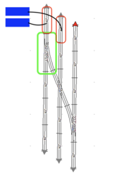
Any guesses on why I seem to be having these issues? I'll attach a mockup of my layout. The green circle highlights the switch in question. The red circles highlight the two terminal tracks I have. The blue bricks are of course the two power masters I have.

Screen Shot 2022-09-26 at 1.52.18 PM

Attachments

Images (1)
  • Screen Shot 2022-09-26 at 1.52.18 PM
Original Post

Replies sorted oldest to newest

The Switch operates fine, it works as intended. It is just hot to the touch. I don’t see what soldering the tabs have to do with this? I've verified all of the wiring, it is correct.

This is not a command switch, either, capable of being programmed. So I don’t see how your reply above has any relevance.

@Calebro posted:

I seem to be running in to some issues with one my fastrack switches, and I'm not certain, but I think it may be causing some continuity issues on my layout.

I have two 360 W power masters powering my three loops of track. Each power master is connected to a loop of track, except the inner loop, which is solely receiving power through track continuity across switch tracks and crossovers.

Last night I was having several problems trying to run some trains on all three loops. The Outer loop worked fine with a ES44AC, the middle loop had a weak spot on a corner with a FEF Northern and 4 passenger cars, and the inner loop didn't want to work at all with 2 F-7s (PWR & DMY) and 4 passenger cars.

When me and father quit for the night and were turning things off, my father stumbled across one of my switches that was "hotter than a branding iron" as he put it.

Any guesses on why I seem to be having these issues? I'll attach a mockup of my layout. The green circle highlights the switch in question. The red circles highlight the two terminal tracks I have. The blue bricks are of course the two power masters I have.

Screen Shot 2022-09-26 at 1.52.18 PM

Is it possible there is a phase reversal somewhere or that the commons are not tied together?  In either case, the switch with the green box around it would be essentially a mid-point where the circuits meet and a high resistance in the switch (eg. folded tabs) could cause a (possibly significant) voltage drop and heat.

After verifying correct phasing among power supplies and tying the common's together, adding more feeder wires from the existing power sources, especially to the inner loop, would improve power distribution more evenly around the layout and help eliminate erratic train behavior.

BASIC 101 of powering a layout.

There is a line in the sand between "starter set" single loop 40x60 carpet layout, and then building an advanced larger layout, running multiple trains at the same time, from multiple power sources.

NO, you should not just slap  2 terminal tracks, one per loop, and worse, NONE on the inner most loop, then "wonder" why you found hot track connections- let alone a switch that was carrying the entire power for a loop from one section to another.

Again, yes, the switch is part of the problem, but the bigger problem is a complete lack of power distribution on your layout, meanwhile loading it down with multiple trains at the same time.

We haven't even touched on phasing of the 2 transformers, suggested isolation joints, or the fact you need wiring or some other way of powering the innermost loop.

Again, there are multiple problems in just this couple feet of track section.

Now this is a more helpful reply than just a link to a past conversation, that had nothing to do with the methods of distributing power to the layout.

I wasn’t aware that I couldn’t rely on the track to carry power around the loop. Yes, I understand the farther away from the power source, the lower the voltage gets. But seeing as I could run two trains the day before, and not have any problems, I didn’t think the problem was not enough power. The only thing I did different from the day before was add another engine.

The only reason I haven’t set up a bus wire is because I didn’t have a permanent plan for the track. I still have some switches to buy and another crossover before I think I will be done with the main loops. I didn’t want to solder track and drill holes in the table if I was still going to move things around.

moving on to your suggestion to remove the joints on the crossover to isolate the loops. I thought leaving them on would help distribute power through the loops. At the time I installed the crossover, I had one 180 W Powerhouse connected to the outside loop, and two 135 W connected to the middle loop. Seeing as both loops now have 360 W of power supplied to each of them, I can see how that would make sense. But again, my thought was leaving them connected would help distribute all of the power throughout both loops.

@SteveH posted:

Is it possible there is a phase reversal somewhere or that the commons are not tied together?  In either case, the switch with the green box around it would be essentially a mid-point where the circuits meet and a high resistance in the switch (eg. folded tabs) could cause a (possibly significant) voltage drop and heat.

After verifying correct phasing among power supplies and tying the common's together, adding more feeder wires from the existing power sources, especially to the inner loop, would improve power distribution more evenly around the layout and help eliminate erratic train behavior.

There could absolutely be a phasing problem somewhere. seeing as that I could run trains on the track the day before with no issue, it didn’t occur to me that this could happen.

Last edited by Calebro

Even with a temporary layout, phasing multiple power sources is a must.  If you need help with this, we'd be happy to help suggest some resources.

After you do that, and equally important, is connecting the electrical commons from each source together with a heavy gauge wire.  I suggest 14 gauge minimum for this with two 360 watt Powermasters.

With a larger temporary layout, instead of soldering connections, I will run feeder wires underneath the track and connect them about every 6-8 track joints to the tabs underneath FasTrack using .110 Faston connectors.

The reason issues arose from one day to the next after adding another train is because this combination of more trains drew more current and caused the voltage to drop even more through the high resistance track joints.  Also, the more frequently FasTrack is taken apart and put back together, the more the connections loosen and the more resistance develops at those joints where the mating pins are.  Adding more feeder wires will help negate this effect.

I also agree with Vernon's suggestion that Isolating the inner and outer loops (by removing the jumper underneath the 1-3/8" fitter piece between the O72 switch and 22.5 degree crossover) would be a good idea, for several reasons.

I run a ZW-L and ZW... the commons on the back of the transformers are tied (wired) together and one (1) common terminal block serves 4 track power districts, all switch motors and 3 separate variable accessory voltages.  That's 8 distinct power districts...  just make sure to segregate/insulate the districts (Hots) from each other... Works great.

OH!  Caleb,  Did you get a handle on the humidity?

Last edited by Dennis-LaRock

Another thought I had. Sometimes it’s the simple things…. Looking at your diagram, specifically at the power source for the outer and inner loops.  Power doesn’t flow through only one direction in the Xing.  All four “legs” of the Xing are connected. So the way it is pictured here, the Xing is getting power from both sources.  I have a similar set up and have to insulate the power at the Xing so only the inner loop is powering it. Insulated sections separate the Xing from the outer and inner loops.   You’ll need to connect power directly to the inner loop.

I run a ZW-L and ZW... the commons on the back of the transformers are tied (wired) together and one (1) common terminal block serves 4 track power districts, all switch motors and 3 separate variable accessory voltages.  That's 8 distinct power districts...  just make sure to segregate/insulate the districts (Hots) from each other... Works great.

OH!  Caleb,  Did you get a handle on the humidity?

Looking into purchasing a dehumidifier. But for now just keeping the valuables inside in air-conditioning.

Add Reply

Post

OGR Publishing, Inc., 1310 Eastside Centre Ct, Suite 6, Mountain Home, AR 72653
800-980-OGRR (6477)
www.ogaugerr.com

×
×
×
×
Link copied to your clipboard.
×
×