I have a half dozen locomotives from the 1918 to 1925 period.  Altogether there are only five or six that seem good and a few of those are uncertain.  So I'd like to start a discussion about how to best handle replacements.

My immediate problem is a 252 that I'm restoring for a friend to use as a Christmas present.  It has a type 5 motor with spoked wheels and a single intermediate gear.  The motor works.  One set of wheels seems OK, in gauge and turning freely.  The other set is a disaster.

I have a few wheels from another 252 and a few from similar locomotives.  Some have a type 6 motor with solid wheels and the double reduction gears.  I see that the spacing is slightly different on wheels for the two motors.  Configurations include

- spoked with 5/64 cast in spacer (could be 1/16 expanded).  

- spoked wheel with gear flat against the wheel

- the gear seems flat on one side and about a 1/32 spacer on the inside.

- the solid geared wheels have a spacer, seems to be 3/32, to clear the inside teeth of the two intermediate gears on the motor.

I got the gear off a bad wheel and took another spoked wheel that I could file flat on the inside and get the gear to be flat against it.  That gear had a gap in the spacer that I filled with Bondo.  Put it all on an axle with what seemed to be a good wheel on the other side that had a cast spacer of about 1/64 and pressed to gauge in my vise, checking very carefully that it is straight.  At first it seemed ok but then it began binding.  I've fussed over it several ways and can't get rid of the bind.

I'm thinking now that maybe I'm on a fools errand and should just get some of Harry Henning's new wheels.  I think my friend would be willing to spend the forty bucks for them if I can figure out how to mount them.  But looking at photos of them in the Henning parts list, I don't see how to match them with the old gear and axle.  

In conclusion, it seems that I should spend the money only for  a motor from a locomotive that I can otherwise restore to original condition and sell for significantly $40.  The other motors can be sold for parts.

------------------------

So who knows something about fixing these old motors ?

I hope my unfortunately lengthy notes will stimulate some good discussion here and hoping to hear from Harry.

BTW, I'm not a prewar collector myself.  I like to accumulate what seems like junk, fix or restore and sell it.  That is what is the most fun for me.

Malcolm Laughlin


Original Post

Replies sorted oldest to newest

Malcolm,

            The "O" wheels you speak of are mfg. by both Jeff (imports ), and ours, which are from the old MEW molds, made here in the U.S.  I can not speak for Jeff's, but ours do not use any kind of spacers before mounting the gear. When I mount the gears , I use a mechanics socket to 'tap' down the gear FLAT over the wheel gear hub, then peen around the square hub w/ a ball peen end hammer.  Probably the biggest error made is in mounting the axle to the wheel. We use an axle tool in a press to guarantee the axle being mounted straight into the wheel. Many of the customers try using a vise, and that can be very frustrating trying to mount straight.  A large drill press can be used to mount the axle into the wheel  also. Note, it has to be like a 'floor model' to be able to apply enough pressure.  The drill press is also great to mount the other wheel. We do not use spacers on the plain wheel side, but only press on far enough so that the gears mesh and side play is only a couple of thousands,  ( very slight side play). 

If you are re-using older wheels, We use a diagonal cutters to place 2  45 degree burrs on the axle end. This will normally suffice to remount the old wheels.

We also have new brass compound gears to replace the original, also new brass motor spacers, axle bearings, axles & armature gears & bearings  collectors & cloth covered solid wire,  if you want to go 100% rebuilt.

Harry  


It's your motor(s) so use what wheels you want but- to my knowledge, the type 6 motors didn't use plain spoke wheels, could be wrong. Both Harry and Jeff have good replacement wheels but if your looking for the older style disc with a round collar in the casting, you'll have to search for Bowser or perhaps Williams NOS. I prefer to find/use original phenolic gears but you'll be lucky to find one good one out of say six. If the inner hole of the gear is worn too badly, they will bind in one direction and not the other, mainly cause of going forward all the time is my guess. Good luck

I've seen a number of replies to my inquiry, but before I read them I'll post some photos of the wheels and motors in question.  Here's a photo tour of some of the pieces.

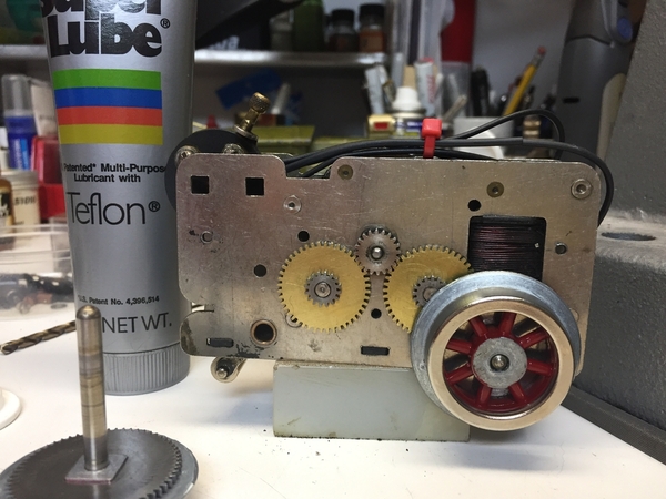
First the 252 motor that I need to get running.

IMG_5123IMG_5124

First of these two is the known good wheel set.   The second is the patched together substitute.  The red spot on the inside of the gear is the Bondo patch to the spacer.

IMG_5125IMG_5127

A question this raises in my mind - does the gear need to be mechanically attached to the wheel, or is pressing them together on the axle sufficient ?  I had to pry it off the bad wheel.

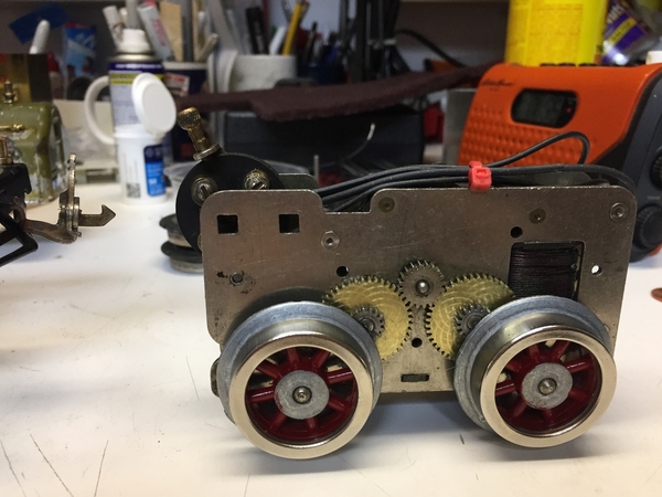
Here is my other 252 motor.  It has good sets of wheels, but I still have electrical work to do.  I did a lot of measurements of the wheel spacing to see if that might give me clue to my problem.  It didn't.  So that's a digression from the story so I'll present them in a separate post.

IMG_5128IMG_5129

You can see that the wheels line up well.IMG_5130

Here are some individual wheels.  First is a spoked wheel with a cast on spacer that is about 1/16".  The second photo is a pair of solid wheels from a type 6 motor.  Note the spacer cast the wheel.  It looks as if the gear has a square hole to fit over this spacer.

IMG_5131IMG_5132

The gear is from a type 5 motor on a 250 series engine.  Note the square spacer on the inside.  I suppose that is to go against the frame, but why is it square ?  The other side is the wheel side after I filed it flat.  It had fragments of the wheel casting attached after I pried it off.

IMG_5133IMG_5134

After all this messing around with wheels, I discovered that my binding problem may be entirely from a different cause.  I'm going to sop here and write about that in the next post.


Attachments

Images (11)
  • IMG_5123
  • IMG_5124
  • IMG_5125
  • IMG_5127
  • IMG_5128
  • IMG_5129
  • IMG_5130
  • IMG_5131
  • IMG_5132
  • IMG_5133
  • IMG_5134

Dimensions.  I did a lot of measuring of the spacing of the wheels on a type 5 motor.  They didn't actually help me fix my problem, but research like this should be published and be available to others.  I measured the dimensions of four wheel sets on type 5 motors.  Results were so consistent that they didn't give me a clue about my binding problem.  Here they are, shown in 128ths of an inch.  Add one inch for the low number measurements

- Outside of tires 87, 90, 91, 97.  The 97 is for a wheel slightly afflicted by zinc pest.

- Interface of tire and flange 26, 24, 26, 34

- Inside faces of wheels 3, 3, 4, 7

The wheel set that I put together seems to differ by 3/64 to 4/64 to 1.5/64 - average 1/16

- gear to face of opposite wheel 121 for three and 124 for repair set.

Don't know if all of this is useful but might be to someone who needs to check these dimensions

Now maybe I have the final solution.  When a solution happens to come to mind can make so much difference in the time it takes to solve a problem !!!

I noticed that one side of the frame is not straight on the bottom.  IMG_5135

Then I noticed that the side has a slight wobble. When it is tight on top the insides of the frames are 3/4 apart.  I noticed that when I held them apart, the separation was 13/16.   Looking at the first and third photos you can see the end of the frame spacer.  In the second it is held together tightly.

IMG_5136IMG_5137IMG_5138

So I tried rotating the wheels in those two situations.  When I held the frame together, all turned freely.  When I released it the motor jammed.  I seems that the minor difference in the angle of the bearings is causing the armature to bind.  Tomorrow I will test the motor with a clamp holding the top of the frame together.


Attachments

Images (4)
  • IMG_5135
  • IMG_5136
  • IMG_5137
  • IMG_5138

Fred,

      Not sure that you realize that the picture of the gears only, still have the remnants of the wheel hub casting still present??  That is not a spacer. Clean that piece of the casting out of the steel gear.  Harry 

Thanks Harry.  I had seen that as a tentative answer to my question and you've confirmed it.  Now I see that the gears were machined with a square hole.  Due to the casting expansion from zinc pest, I had at first thought it was part of the gear.  But that doesn't really make sense from a manufacturing point of view.

I will order a set of those wheels today and use them on another type 5 motor that I have.

Next question, what about a type 6 motor on which there needs to be a 1/16 gap between the wheel gear and the frame to clear the teeth on that phenolic gear that engages the pinion on the armature ?

Taking that apart wasn't so easy - took me about an hour of thinking and doing.  If anyone knows an easier approach, please speak up.  Here's the illustrated story of gear removal.

I began with this set.  First step is to remove the axle.  Photos before and after.

IMG_5139IMG_5140IMG_5141

Note the spacer projecting from the gear.  This is for clearance for the intermediate gear.

Now the problem is separating the gear from old wheel.  You can see the square hole in the gear is obscured by the expanded casting.  So with my King Kut knife and a file I removed enough to make the whole square visible.   The idea was that the square part of the casting would pop out when the gear is removed - didn't happen.

IMG_5142IMG_5143

The time consuming difficulty was removing the gear.  There wasn't any obvious way to get between the gear and the wheel to pry it off.  After messing around with a chisel, I tried an abrasive cutting disk on my Dremel tool.  Could have saved time if I'd thought of that first.  I was able to dig a slot between the back of the gear and the casting to insert a small cold chisel.  Finally it popped off.

IMG_5144IMG_5145IMG_5146

Thefirst photo shows wheel and gear.  Note that square part of the wheel casting broke off and stayed in the gear.  Easy to pop off but note the gear center is not square.  A bit of work with the knife and file and I've got a gear with a square hole ready to mount on the MEW wheels.

Still one mystery - where did that spacer go ?  I had expected a washer, but it seems to have disintegrated with the casting.  I would suppose that a 1/16 washer with a hole the diameter of the axle would work.  Any advice on that ?

So now I will order that MEW spoked wheel set for my 252.

Malcolm Laughlin

Attachments

Images (8)
  • IMG_5139
  • IMG_5140
  • IMG_5141
  • IMG_5142
  • IMG_5143
  • IMG_5144
  • IMG_5145
  • IMG_5146
Last edited by mlaughlinnyc

Don't ruin that wheel/axle assemblyif it's still good. Ya might need it. Harry ma

Those are the key words.  The wheel casting are mostly unsalvageable.  I did manage to salvage one that didn't have any chunks broken out of the rim.

Now I have some good steel tires around junk castings.  The only modeling use I can think of for them is part of a scrap gon load or the junk pile behind a model of the shop.


Now the problem is separating the gear from old wheel.  You can see the square hole in the gear is obscured by the expanded casting.  So with my King Kut knife and a file I removed enough to make the whole square visible.   The idea was that the square part of the casting would pop out when the gear is removed - didn't happen.

The time consuming difficulty was removing the gear.  There wasn't any obvious way to get between the gear and the wheel to pry it off.  After messing around with a chisel, I tried an abrasive cutting disk on my Dremel tool.  Could have saved time if I'd thought of that first.  I was able to dig a slot between the back of the gear and the casting to insert a small cold chisel.  Finally it popped off.

Still one mystery - where did that spacer go ?  I had expected a washer, but it seems to have disintegrated with the casting.  I would suppose that a 1/16 washer with a hole the diameter of the axle would work.  Any advice on that ?

So now I will order that MEW spoked wheel set for my 252.

Malcolm Laughlin

Malcolm, Generally, when one is separating the wheel from the gear, only the gear can be saved as a functional piece. Just find a small dull chisel, put in the slot between the back of the flange and the gear and give  it a couple sharp rap with a hammer and the hub will pop off. A little hammer and punch in the gears center will clean it up. Spacer was integral to the hub. Having some shims washers about is a good idea to help you get the gauging right.

One more question.  I have this spoked wheel with a 3/32 deep circular spacer in the casting.  Don't remember which of the engines sitting in my back shop it came from.  Anyone recognize this one.  It doesn't fit with any of the MEW store photos.

IMG_5131

No longer offered that way. the cast spacer is machined off... too many variables for fitment and hobbyists are more inclined to be able to use shim washers than can machine the hub.

OK...I am sorry to ask what might be a stupid question but here goes anyway.  I have several locomotives with zinc pest in the drive wheels but they are still attached to the axle and the wheel on the opposite side.  How do you get the old wheel off?  Just destroy it?  Does someone market a wheel puller? 

Sorry to ask such a basic question.  I did rewheel a Lionel Std Gauge #8 years ago (like in the 1970's when I was much younger and likely smarter) but I can't remember how I got the old wheels off. 

Thanks

Don

Rob English is right on spot.  I reached about the same conclusions.  So I'll be sure to have a few washers of various thicknesses as I'm working on the engines.

As for driving the axles out of the wheels, no need for a wheel puller.  You need to support the side of the motor on both sides of the axle.  I usually can work that out with a few pieces of wood and a clamp or two.  I'll post some photos of how I do that.


Here's an illustrated example of how I rig a motor for wheel removal.  First I support the underside of the motor frame at two points on opposite sides of the axle.  A good assortment of wood scraps is very useful here.  You can see that one side is clamped, one clamp suffices.

IMG_5158          IMG_5159       IMG_5161

For driving out the axle you need a round piece of steel with a flat end and diameter slightly smaller than the axle.  A 8d nail is about the right size.  I use 1 1/2 inch roofing nails that are an inch and a half long.  You can see how I hold it in the photo.  As I don't have a third hand, I can't show the hammer because the second hand is holding the camera.

Holding the nail I tap it lightly with a large hammer and gradually increase the force of my hammer blows until the axle begins to move.  Be careful with the force, it takes less than driving a nail into a pine board.  And be very careful to keep the nail vertical and centered.

The final photo shows the modified nail that I use.  I cut the tip off with a hack saw and file to be sure the end is flat.

Attachments

Images (3)
  • IMG_5158
  • IMG_5159
  • IMG_5161

Add Reply

Post

OGR Publishing, Inc., 1310 Eastside Centre Ct, Suite 6, Mountain Home, AR 72653
800-980-OGRR (6477)
www.ogaugerr.com

×
×
×
×
Link copied to your clipboard.
×
×