I recently picked up a Lionel Norfolk Southern Genset (6-28323) that had known issues.  I took a chance on it partly because I knew if I couldn't figure it out my wonderful friends on this forum always try and help.  Well, I'm kind of stumped so that's why I'm here.  I'm fortunate because I also have the same loco in UP livery (6-28314) so I can use it as a control or test bed. 

The NS arrived dead (no sound, no movement, no lights).  I verified track voltage at the J1 connector on the motherboard.  I'm in luck that Lionel published a schematic on the 691MB14A01 motherboard (link provided below).  First thing I did was to swap sound boards between the units and the NS board worked on the UP but not vice versa.  Next I swapped the RS Power Boards and the NS loco was playing UP sounds.  That proved the motherboard was working at least on the sounds side of the house.  At that point we have confirmed the original NS RS Power Board is failed.

Now onto to movement.  I reviewed the schematic and then went probing.  I did research on this forum and found that Marty Fitzhenry recommends following the 5 volt signal.  I was probing around on the motherboard and the DCDS (motor driver) board and she started moving.  Not sure what I did.     I moved it several more times, verified the couplers fired but held off on checking smoke unit.  I noticed that the ground lights come off the DCDS and they were working but seemed dimmer than the UP.  I was checking voltage (while moving slowly) on a ground light connector and I caused a short on my probes or rail or somewhere.  Well, now she don't move again.  I've done a reset per the manual.  Sounds still work (using the UP boards).   Couplers still work. 

I tried to repeat all the probing, wiggling and jiggling on the motherboard connectors and DCDS connectors but no luck.  I have 5 VDC on various connectors on the MB.  However, we should probably focus mostly on the MB connectors to the DCDS.   

So folks, looking for some friendly advice to systematically troubleshoot this Genset to prove what board, connector or conductor is bad.     

Motherboard Schematic

Last edited by Steims
Original Post

Replies sorted oldest to newest

Actually, it is on the schematic Chuck, just with a different number.  I'm assuming that's because it's only controlling one smoke unit and not three of them.

In any case, lack of movement is unlikely to be associated with the smoke unit, I'd be looking at the DCDS and it's connection to the the system.  There's only a handful of signals going to the DCDS, that's where I'd be looking first.

Attachments

Images (1)
  • mceclip0

The cab is removed so the harness between the chassis and the that smoke control board is disconnected.   Also, the light harness is disconnected which only keeps the ground lights in play.   

I really would like the focus on what is preventing movement.   Where should I be measuring to support/refute the motherboard and DCDS.   I can eventually swap those components between the Up and NS but that’s a lot of work.  I really want to find with my meter.


I'd be tracing all the wires from the DCDS to their destinations.  Top suspects would be is serial data getting from the RCDR to the DCDS.  You'll notice that the serial data goes from the RCDR to the RS 6 motherboard, and is then forwarded to the DCDS on pin-1 of J2.  It also goes to the IR LCS board and the headlight board.  I have no idea if the RS 6 MB is buffering those signals, but I suspect due to the distribution that they probably had to boost them on that board.

Of course, the other place to look is the actual motor connections, if one of those is bad, clearly the motors won't be running.

RS Serial is apparently repeated, and may have either information stripped out or added.  It's interesting to note it goes to the track LCS transmitter.  CAM is a generated pulse that tells the RCDR that the locomotive is moving, it's like the wheel cam on old TMCC locomotives.  Serial data is constantly changing, the only way to really view it is with a 'scope.  I would only measure the 5V to the matching ground as not all grounds are created equal.  I suspect many are, but I don't know for sure.

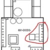
I think we got this Genset figured out.  After a few hours of poking and prodding I eventually swapped motherboards between the inop NS over to the UP.  That wasn't the problem.  So just as I was getting ready to swap the DCDS boards I was starting to disconnect the harnesses and noticed there is one connector that has a 3 legged triac looking thing soldered to it (see schematic below and pic) .  GRJ later corrected me that is actually a Voltage Detector.  Well when I swapped this little doodad between locos the NS started moving.  Not sure where to find a replacement (Lionel DCDS parts photo does not show it) but currently looking at some electronics suppliers.

BTW, the schematic link above for ES44AC does show a 691MB14A01 motherboard.  These Genset actually use 691MB14A00 but that didn't impact or ability to troubleshoot.

Big thanks to GRJ for his coaching and advice to find the problem. 


DCDS Genset


DCDS VD Connector


Attachments

Images (2)
  • DCDS Genset
  • DCDS VD Connector

Add Reply

Post

OGR Publishing, Inc., 1310 Eastside Centre Ct, Suite 6, Mountain Home, AR 72653
800-980-OGRR (6477)
www.ogaugerr.com

×
×
×
×
Link copied to your clipboard.
×
×