Really like the Z-Stuff crossing gates and signals and recently picked up the 1020 set of two crossing signal light flashers. What I'm not fond of are the relatively large rectangular black bases that come with them. They take up a fair amount of space on the layout and I'd rather just install the post with the flashing lights as a stand alone device.
The set comes with two sets of light poles and two dwarf signals with built-in IR detectors that trigger the flashing lights when a train passes by. You can either use the two poles placed diagonally across from each other, on both sides of a track, or you can mount them independently as individual poles at different locations on your layout. One pole has an electrical cabinet mounted on the base which houses the ringing bell/speaker and the other one is just the pole.
In the past, I have dug out a hole in the foam top layer of my layout within which to sink the black bases and then covered them up with vinyl spackling, brown paint and turf, but that's a lot of work and still requires the space to sink the bases into. A simpler solution was just to separate the light poles from each base and then mount the post on the top of the layout and the base with all the electronics on the under/plywood side of the layout.
First, I bench tested all the connections and dwarf signals on the bench to insure everything was working correctly, which it was.
I began by unscrewing the cover plate on the bottom of each base. There are three (3) thin wires that run from the electronic board to the pole - two black wires and one blue wire - all about 30 gauge or smaller. In order to not confuse the black wires with each when reconnecting everything, I colored one black wire with a silver Sharpie. I then cut all three wires about halfway between the board and the pole, leaving about 1.5 inches or so on each end. Next, I unscrewed the two small screws that hold the pole on the base and removed it from the base, so that it was no longer connected to the base. The pole is not glued together at the bottom where it connects to the base, so I carefully spread the pole a little bit apart and applied a few drops of fast-setting CA glue to keep it together - note that the wires run through a channel inside the pole, so be careful to make sure they all fit back into the channel before gluing the bottom section together. I then cut out a small hole for the base wires to poke through and screwed the base cover back on.
The remaining length of the three wires on both the board and the pole are too short to run up through the layout (about 1.5" thick) and easily reconnect, so I braided and soldered short lengths of the same gauge wire to each of the six (6) ends to extend the wiring through the layout and added some shrink wrap at the connection points and stripped all the wire ends. I drilled a small hole through the layout where I wanted to mount the pole and climbed under the layout with the base in hand and fished the three wires from the base up through the hole and mounted the base securely to the underside of the layout using the screw and mounting hole provided in the base. It helps to have someone above the layout to grab the wires and hold them in place while you are mounting the base from underneath.
I then brought my soldering iron over to the layout and braided, soldered and shrink-wrapped the wire ends from the pole to the wire ends from the base making sure to solder the correct black wires together. The base of the pole has two plastic prongs that stick down into the foam and I applied a few drops of CA glue to the underside of the pole bottom and pushed the wires down through the hole and pushed the pole into the foam and that was it.
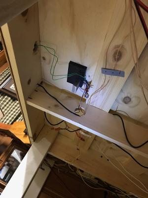
I then mounted the dwarf signal and connected all the wires under the layout and it works perfectly with pole on top and the base hidden below. On the pole with the electrical cabinet and bell, the base was mounted upside down to the underside of the plywood layout, so that the cabinet points down.
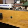
You will also notice that I installed a simple green push button switch to turn the bell on/off if the sound repetition gets too annoying. I drilled a hole through the layout fascia and mounted the switch. I then connected the two green wires from the base to the switch.
A nice project and an alternative way of mounting the flashers that isn't too complicated for anyone interested.


