Mike CT, Sorry for the delay in responding, but my days have been a little busy lately.
I have viewed and enjoyed the slide show of the club as well as all of the pictures and info provided either in or through your post.
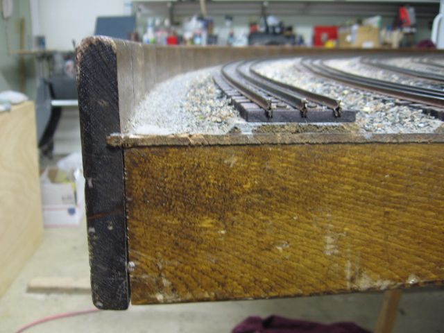
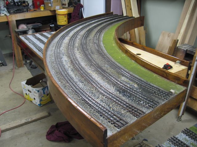
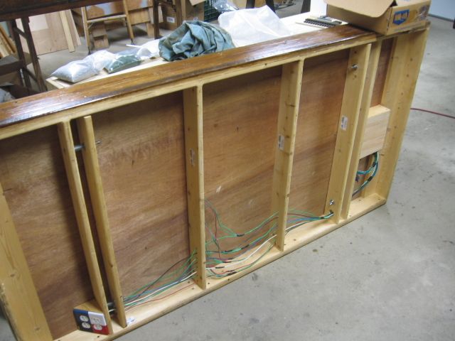
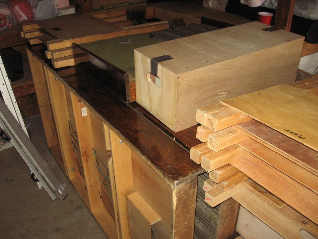
The 37 1/2 inch width is larger than most, but with the four main lines I guess it is necessary. You are right insofar as people being impressed by the curved corners, you can add me to that list. What is the radius of the outer most curve on those corners. What is the minimum curve on the layout; I'm guessing that would be at the entrance to the turntable area?
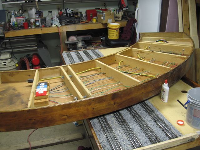
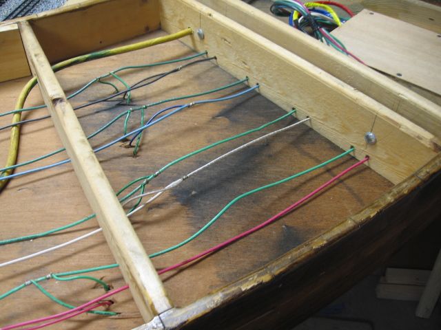
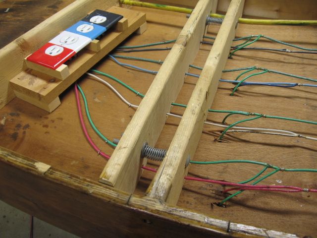
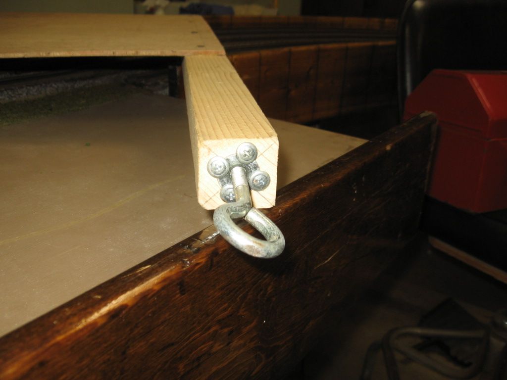
Your carraige bolt/spring & wing nut assembly is indeed interesting, do the leg assemblies just get tightened between the clamp boards, or do the carriage bolts go through the leg
tops?
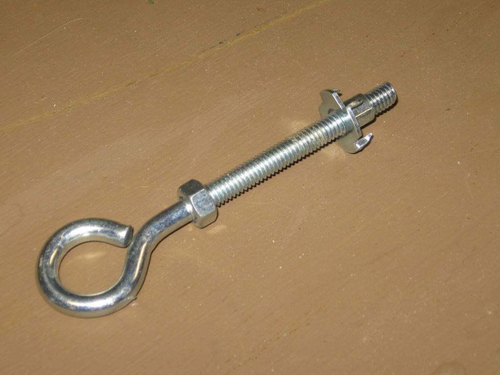
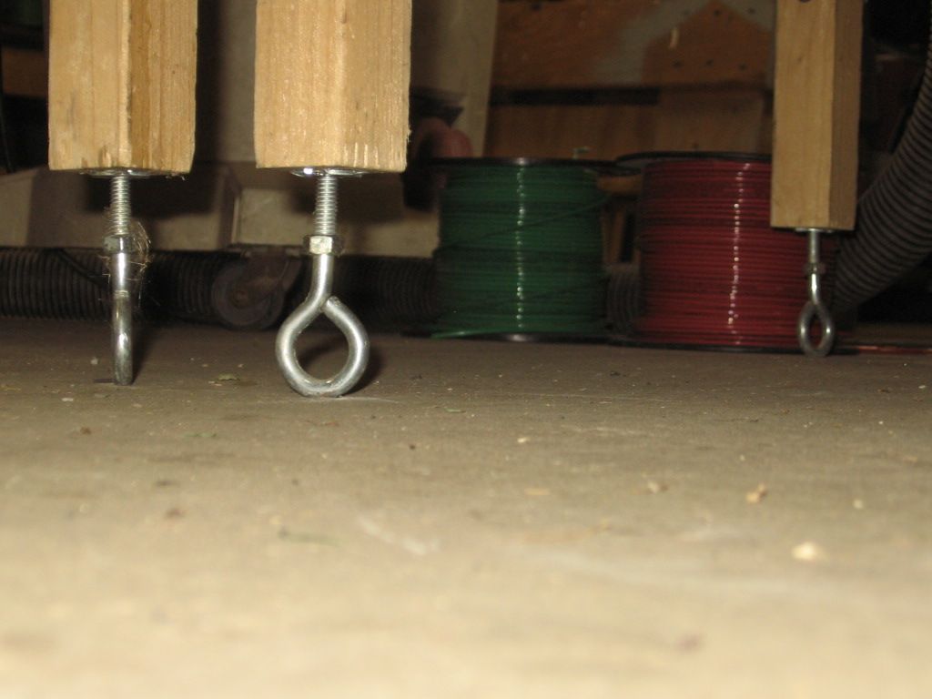
Are the eye bolts used for ease in making height adjustments only, or do they serve another purpose as well? Are the leg holes drilled out very deep to accept the length of the eye bolt?
In any case a very interesting post that I'm sure I will refer to many times over, thank you for posting. Rich