In my basement layout [dedicated room, 4 tiers [including the floor as Tier 1!] of 12' X 12' track -- 13 track lines with curves ranging from 031 to 072 and even some mixed bag stuff], my main power transformers include two MRC AH601 270 watters, two venerable 275 watt ZW's [Sidebar: Saw an early Lionel early 50's vintage ad reproduction just recently, are you ready for this, the classic ZW, brand new, $39.00 [!] and the equally classic KW for $31.00 [!] with Lionel boxcars going for less than $3.00 !] and two 190 watt KW's ], anyway, one of the rather fast acting circuit breakers on one of my MRC dual power transformers [5 year MRC warranty as memory serves] suddenly popped up on the left side when one of my older cube box cars had a wheel go off the track [Sidebar: WHY does this ALWAYS seem to happen when the boxcar [or whatever] is at the far end of the layout and the most inconvenient spot to get to! ], anyway #2, I fix the boxcar wheel, go back to the MRC and press down on the circuit breaker button to reset it annnnnnnd .... nothing! No power! The right side of the MRC, fine, the left side, dead! Triple checked everything, nothing! The left side did a Jacob Marley on me and went "as dead as a doornail." And hey, these much newer dual power MRC's are hardly vintage ZW's or KW's so what's with the non responding circuit breaker when manually reset!

The fix: Once again, WHERE is my layout located? The basement. And again, the twin culprits of basement electronics, humidity and electrical oxidation issues. Question: Can an old trick save me a disassembly of the transformer on the theory that the circuit breaker may not be broken and any possible oxidation or "dust gunk spot" is minor ?  What's to lose? I cut the power to the transformer and I then took a needle nose pliers and lifted ==UP== on the left side circuit breaker which of course manually placed it in its UP [or "tripped" position] position [while also instantly verifying that the up position still worked via the discernible click] and I then covered the top of the plastic circuit breaker button with a piece of tape while taking my handy-dandy tack hammer [WAAAAITTTT  a moment now, stay with me on this!] and giving the button a firm but not heavy "tap" or "bop" if you will and then I repeated the process 4 times. On the 4th "tap" or "bop", I left the button in its normal DOWN position [or NON tripped position], powered up the transformer and the left side power instantly came back to life! It doesn't take much for the breaker to fail due to even a minute spec of dust or even minor oxidation. The "cure" was the tap/bop [lightly!] and it's been working fine ever since! I then ==purposely== nudged a dead slow moving engine wheel off the track, the circuit breaker tripped as expected and popped UP but this time upon manual reset of the breaker by pressing it downwards, all was fine!

Clearly, and no argument whatsoever, opening up the transformer would be in order and a thorough cleaning of its innards and my usual ritual of using brush on Deoxit here and there, but for a fast fix, the tack hammer "cure" worked. Who says taking a hammer to a layout issue has to necessarily be a bad thing? ;-)  This too, various "fixes" and even if only temporary in nature can be said to be unorthodox but, and in all fairness, they can work! Indeed, over the years and such things termed "tips and tricks", I read and used various unorthodox "cures" but if they work, well then, where is the argument for at least a temporary fix until the more orthodox fix can take place.  --- Doc Tony   

Original Post

Replies sorted oldest to newest

OK.  I opened up my transformer and saw nothing unusual.  I then removed the diode array on the bad side of the transformer.  I removed the screws on the bottom of the diodes and found one of the copper strips had broken away from the board.  I resoldered it back in place and reassembled the transformer.  When I plugged in the plug and moved the throttle levers, I got 3 amps (only moved levers a little way) but showed no voltage on either meter.  The lights on my passenger cars lit up alright but the engine didn't move at all.  All my accessories work fine but trains won't move.  What could the problem be?  It seems strange that everything works except the engines.  That tells me the accessories are seeing voltage.  HELP

@Jetman posted:

OK.  I opened up my transformer and saw nothing unusual.  I then removed the diode array on the bad side of the transformer.  I removed the screws on the bottom of the diodes and found one of the copper strips had broken away from the board.  I resoldered it back in place and reassembled the transformer.  When I plugged in the plug and moved the throttle levers, I got 3 amps (only moved levers a little way) but showed no voltage on either meter.  The lights on my passenger cars lit up alright but the engine didn't move at all.  All my accessories work fine but trains won't move.  What could the problem be?  It seems strange that everything works except the engines.  That tells me the accessories are seeing voltage.  HELP

I'm 99% sure you messed up on that repair as those were switches, and you've likely shorted it.  I would go over and read this topic. I've copied the one comment with pictures but again suggest reading that entire topic.

https://ogrforum.ogaugerr.com/...c/146001354979371477

@boomer0622 posted:

The left side of my transformer went dead after pushing the directional button, but after sever pushes, it came back to life.  I put a piece of tape over it so I wouldn't push it again until a couple days ago. Oops !

Thanks to you guys and this thread I got the courage to open it up and knew what to look for.       Here are a couple pictures;

The first thing I noticed was the copper tab catching on the wire, upper right, but it hadn't worn through the insulation, so I bent the wire out of the way.

DSC04305 [1024x758)

After removing the yellow plastic cover, sure enough the solder joint for the tab had come loose.

DSC04308 [1024x758)

Now off to Harbor Freight for a soldering gun,  I guess a 25 watt will do the job ?

Doug

@Jetman posted:

All 3 circuit breakers are good.  My problem is I see AMPS when I move the throttles but no VOLTAGE on the meters.

OK, let's go over the circuit. You said you found one of the switches broken- that's what those strips form- switches.

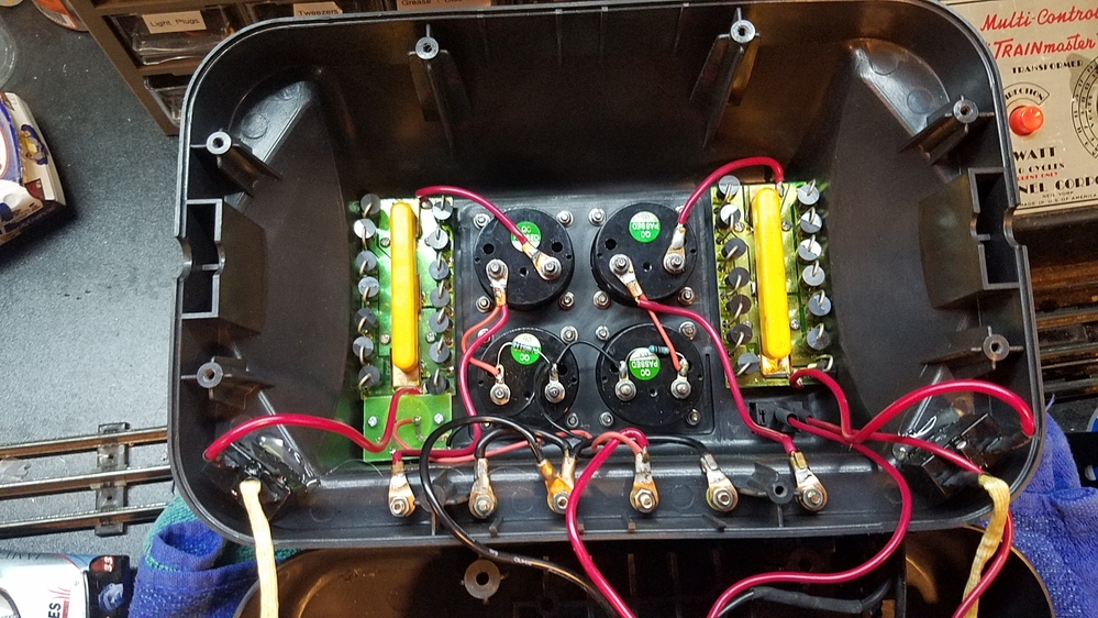
ALL 3 must be NORMALLY CLOSED for power to flow through the circuit board and bypass the diodes. Power comes in one end of this board and comes out the other as long as the direction switch contact is closed and ideally all 3 switches are closed bypassing the diodes basically being a straight through shot.

This plastic bar with springs pushes down on those so they make contact in the normally closed position. The buttons poke through the board and press the copper or brass contacts upward thus opening that switch in the circuit. Key point, ALL the power must go through all 3 switches (voltage and current) to reach the output terminal. Again, this yellow plastic bar and the 3 springs press against the copper or brass contacts to hold them normally closed.

Schematic taken from this topic https://ogrforum.ogaugerr.com/...07#76185252841267907

That is more or less a copy of the circuit board we are looking at minus another switch that  opens circuit for directional control.


@Jetman posted:

OK.  I opened up my transformer and saw nothing unusual.  I then removed the diode array on the bad side of the transformer.  I removed the screws on the bottom of the diodes and found one of the copper strips had broken away from the board.  I resoldered it back in place and reassembled the transformer.  When I plugged in the plug and moved the throttle levers, I got 3 amps (only moved levers a little way) but showed no voltage on either meter.  The lights on my passenger cars lit up alright but the engine didn't move at all.  All my accessories work fine but trains won't move.  What could the problem be?  It seems strange that everything works except the engines.  That tells me the accessories are seeing voltage.  HELP

Most likely, you failed to fix the direction button one as that would create the open circuit. Otherwise, the other 2 being open circuit would cause DC offsets. I guess in one scenario, one could have both whistle and bell at the same time but that would then tend to conduct through.

Last edited by Vernon Barry

Another possible scenario, the voltmeter is shorted?  There are no full schematics for these posted that I have found and do not have one of the transformers on hand at the moment to open and reverse engineer.

The Amp meter is in series in the circuit to the output terminals. If it was shorted, it would never read any amps. It also would not affect the circuit much as this would just conduct power anyway. However, open circuit meter would read nothing, but also pass no current.

The volt meter should be in parallel to the output. If it was shorted, the amp meter would read amps, the volt meter would read zero because it's shorted. Again, being parallel to the output, this is one of the few things that could short and cause the problem.

The Diode board for whistle, bell and direction is in series. If it fails open circuit- no power and no amperage. It normally is shorted straight through. Failures of the switches either cause open circuit or pass all the power through the diodes in the form of the DC offsets.

Last edited by Vernon Barry

This was made from the information that has been posted and looking at diagrams and pictures of torn down transformers.

Again, pictures taken from this topic by @Trainlover9943 https://ogrforum.ogaugerr.com/...0#146001354984582670

So yes, the above schematic is pretty valid for one channel.

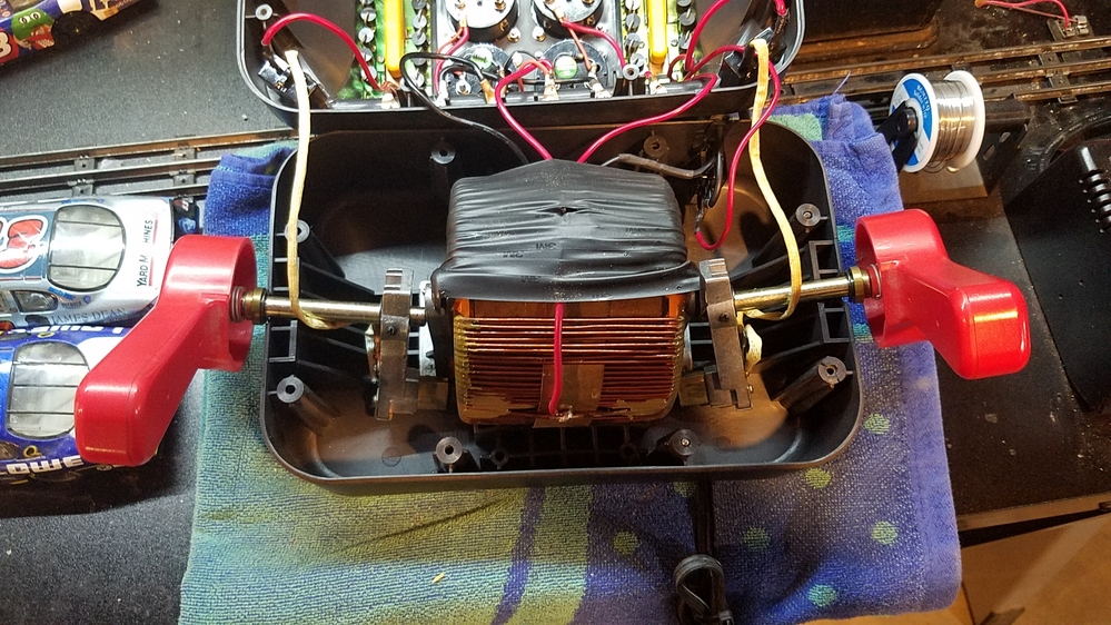
Wipers and main core transformer (torrid)

The upside of the PCB that faces the downward pressing buttons by the user.

Notes added

Attachments

Images (2)
  • mceclip0
  • mceclip0
Last edited by Vernon Barry

Add Reply

Post

OGR Publishing, Inc., 1310 Eastside Centre Ct, Suite 6, Mountain Home, AR 72653
800-980-OGRR (6477)
www.ogaugerr.com

×
×
×
×
Link copied to your clipboard.
×
×