
Hi, this is my first post on the forum. Maybe someone can help me with a problem replacing or repairing a MTH constant lighting board.

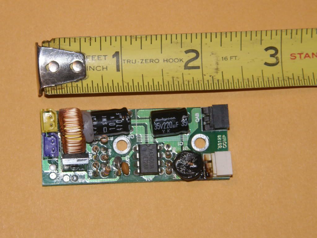
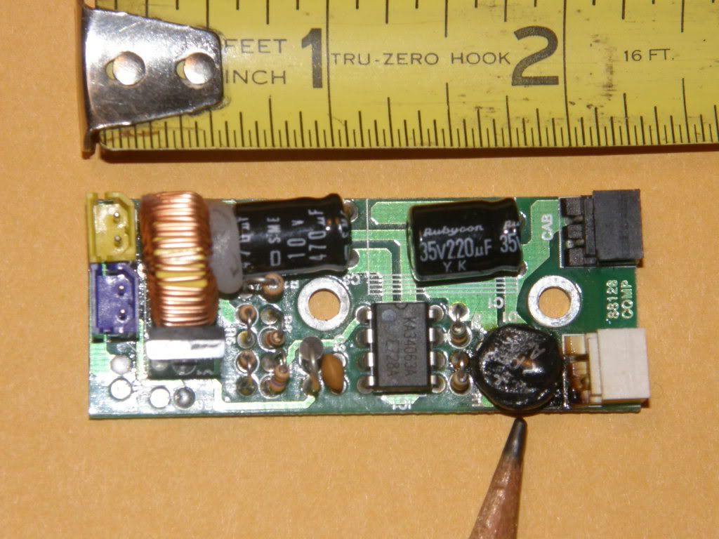
The constant voltage board in my MTH 20-3031-1 PRR G-5 ten wheeler recently suffered a component failure at the board's power input. Although badly burned, the component looks like it might have been a capacitor.

I removed the board and the loco runs alright without it, except that it no longer has a headlight, front marker lights, smoke, etc.

I contacted Midge at MTH service and, so far, she has not been able to locate a replacement board or any schematic that would positively identify the burned component. I also asked our local authorized MTH service center to locate a replacement board and they, too, were unable to do so. Although the loco is not too old, circa 2000, component replacement has apparently become practically impossible.

This model has great sentimental value for me as I grew up with its prototype G-5's running on PRR's Grand Rapids & Indiana branch. I would like to keep it in top notch shape. Does anyone have any ideas or sources for replacing or repairing this board?
Original Post

Replies sorted oldest to newest

Usually they use a small board in front. Consists of a single diode,half wave rectifier and a capacitor,along with a regulator 7806 I think. Best way IMO is just to convert to LED lighting. Use the CL2-n3 chip if you want constant voltage or a 7805 circuit.


Use these for a headlamp

http://cgi.ebay.com/New-50PCS-...&hash=item439bb24bbd

Circuits shown here

http://www.jcstudiosinc.com/Bl...d=619&categoryId=426

http://www.jcstudiosinc.com/Bl...d=408&categoryId=426


And these for general lighting

http://www.ebay.com/itm/New-50...&hash=item3a38123e65

For cab lighting you can also use the top ones.

The marker lights I think are red LEDs already. From a 7805 circuit install a 100 ohm resistor to each one.

More general information on LED lighting is here in various posts

http://www.jcstudiosinc.com/Bl...tegoryMain?catId=426

Dale H
Was this a PS-1 unit? I just finished working on a weaver with MTH PS-1 system installed.

Do you know the rating of the bulbs? You can test with a 1.5 volt battery, then a 3V, then 6 volts to see.

The 6 Volt CV board had a 7806 VR, 4 IN4004 diodes for full rectification, and the Capacitor was a 35V 330 ufarad polarized capacitor. This unit was just for lights.

Not sure why you lost you smoke unit, unless your unit is a PS-2. G
quote:
Originally posted by GGG:
Was this a PS-1 unit? I just finished working on a weaver with MTH PS-1 system installed.

Do you know the rating of the bulbs? You can test with a 1.5 volt battery, then a 3V, then 6 volts to see.

The 6 Volt CV board had a 7806 VR, 4 IN4004 diodes for full rectification, and the Capacitor was a 35V 330 ufarad polarized capacitor. This unit was just for lights.

Not sure why you lost you smoke unit, unless your unit is a PS-2. G


This is a PS-1 unit. I think the smoke unit may have been grounded to the CV board. I have inspected another CV board in a similar unit and that one appeared to have a 470 uF 10W capacitor. I believe the bulbs are 6 volts.
quote:
Originally posted by Mortsman:
John, thanks for the advice. The two pictures are on Photo Bucket now Here is what I hope is the "IMG" code: . See my comments on Photo 2.

Let me know if this works. Learning new things is a little different when you are nearly 75.


Not working for me. Was it supposed to put the image on the posting...?
OK, now we are getting somewhere. Your circuit board is going to be specific to your engine. Not likely you are going to find a direct replacement, unless MTH still has one around, but probably not. Might be able to repair your original one. It looks like a common rectifier which is easy to replace and I have them in stock. The question is what took it out. If not, I have new constant light boards for the scale GS-4 steam loco. It is similar, just a tad longer, but has the same sockets. If space is not a premium, this board would probably work, but I would try to fix your original one first.
It's the right shape and size...and I see a + that would be on a bridge...only thing is wonder why it burned out. Could have self destructed...if it were mine, I would try a new part. Look over the resistors etc. for any brown-ing. Is that connector on the right top normal all black like that? Oh...check the capacitor on the right top to see if it is shorted. If something on the board caused it, it could most likely be that cap.
Chuck, thanks for hanging in there with me. Yes, a picture is worth a thousand words.

Dale, yes the component does have 4 leads on the bottom. The path of fire went directly from the lead nearest to the power input to the second lead connected to ground.

With a magnifying glass you can still read the distorted numbers on the melted top. They seem to be &pc& with AL152 below.

Chuck, I don't know what caused the short. The engine was prancing along around a curve in good shape when it suddenly made a distorted death rattle with the whistle and came to a stop. I had the track power off within seconds but the white smoke had already enveloped the drivers. The engine ran fine again when the CV board was removed.

Chuck, you have the answers so far. Do you have a service and repair business?
How can I contact you to make it all happen?
That engine is a Proto 1 engine.What do you use to power your layout?
The KA34063 is a switching regulator which did not burn and since the
bridge rectifier did burn, the cause could be a voltage spike. I could
not find a part to match the rectifier number. The rectifier could be
only 50v which could blow with voltage spikes.The bridge should be replaced
with a brige of at least 200v.
quote:
Originally posted by pa:

I could not find a part to match the rectifier number. The rectifier could be
only 50v which could blow with voltage spikes.The bridge should be replaced
with a brige of at least 200v.


The marking is probably correct as it is on a similar part in this QSI board topic. Given the package type I'd guess it is a generic xx152 type bridge - 1.5 Amps, 100/200V.

If as you suggest the smoke unit gets its DC power via this board, then the melted bridge explains the no-smoke loose end.
What plugs into this board? Head light and Marker (Blue/Yel?) What about white and black plugs?

One needs to be power in, most likely white. Black says cab, was that cab lighting?

So still not sure were smoke unit fits in?

Could have been a random failure from a spike, or one of your outputs had an issue like a lighting harness pinched wire.

You can also check for other components being as they should. Diodes that block, resistors with appropriate values. You can then replace the diode, power it up with current meter in place to see how it is. Then plug in lights for final test. Does look like the failure was a short between AC input. Probably still shorted which is why the engine won't run with it installed. G
quote:
Originally posted by GGG:
What plugs into this board? Head light and Marker (Blue/Yel?) What about white and black plugs?

One needs to be power in, most likely white. Black says cab, was that cab lighting?

So still not sure were smoke unit fits in?

Could have been a random failure from a spike, or one of your outputs had an issue like a lighting harness pinched wire.

You can also check for other components being as they should. Diodes that block, resistors with appropriate values. You can then replace the diode, power it up with current meter in place to see how it is. Then plug in lights for final test. Does look like the failure was a short between AC input.

Probably still shorted which is why the engine won't run with it installed.G


Thanks, pa, stan and GGG, for your interest. I hope I can answer all of your questions.

The white plug is AC in. The black plug is for the cab lights. The yellow plug on the upper left corner is for the front marker lights and the dark blue plug next to the yellow plug is for the headlight. There is some slight blistering on the bottom of the board under the headlight plug. Maybe there is a pinched wire in the headlight circuit going around the smoke unit. I will check that out too.

The only connection to to the smoke unit that I can see is a ground wire that comes from under the smoke unit and connects to the board under the left attachment screw. I reattached that ground wire directly to the boiler shell after I removed the board.

Track power is a MTH Z4000. As for the possibility of a transient voltage spike, I have since added bidirectional protection diodes to the Z4000 outputs. (shame on me, locking the barn door after the horse is stolen).

GGG, I appreciate the testing tips. I will let you all know what we ultimately find is the root problem. Thanks to all of you, this has been a great learning experience.
I think you have this well in hand! I do think the burnt trace near the headlight is a tell.

I have a QSI board with the same issue and the leads to the headlight were damaged with conductor showing.

I have another QSI board with a trace burned out. After I repaired it, I checking continuity around the bad area and had continuity to an area that should not have had it. Walked it back to a diode pair that was shorted.

Follow the scorch marks! Big Grin G
Post

OGR Publishing, Inc., 1310 Eastside Centre Ct, Suite 6, Mountain Home, AR 72653
800-980-OGRR (6477)
www.ogaugerr.com

×
×
×
×
Link copied to your clipboard.
×
×