
Ted S posted:

Mark, I'm not sure that 0x09 has anything to do with the speed or odometer function.  The byte at 0x08 does a pretty good job by itself of describing the effective gear ratio and by extension, motor revolutions per inch, stripe count per inch, stripe count per second at a given speed, etc.

Your sample data only confirms what I already knew.  All diesels are geared the same at 10.5:1 and typically have the same size wheels. 

The formula for the approximate gear ratio is: Driving Wheel size in mm * the value of 0x08h as an 8-bit integer * 0.00552. 

I'm not sure why some diesels have 0x54 and others 0x55.  But the difference is only 1 in 84, or about 1.1 percent which is within tolerances for double-heading.   I also can't explain why the formula doesn't work out to the exact value in every case.

Ted, I'm going to spend some time considering your point about the byte at 0x08. I can modify RTC to use only that byte in the DTO and DOD calculations. I'll post my results.

The one strong point against it (at least to me) is that when the remote reads up the scale factor, it always reads up two bytes. Reading bytes out of RAM is fairly expensive in terms of bandwidth over the track. In every command that I've looked at, the remote never reads up any extra bytes. If it could work with just the byte at 0x08, it would not have read up the byte at 0x09.

Mark


Mark I'm not arguing with you, I would love to help.  I just don't know what 0x09 means or how it's used.  0x08 by itself gets you pretty close to the scale factor.  Way too close to be a coincidence, but not exact, and that bothers me too.  Unless 0x09 is some kind of "fudge factor" (see theories in my post), I just don't know.

Ted S posted:

@Tiffany your loco has a value of "96" in the sound file, byte 0x08.  Based on the info you provided (and my past experience), I would guess the gear ratio is 17:1.  You can verify this by taking the shell off and turning the flywheel by hand.  Make a tiny mark on the flywheel and driving wheel rim so you don't lose count.  Turning the flywheel by hand won't hurt the loco, and it's a good way to see if something is binding in the drive train.

Speaking of which, @49Lionel what kind of motor does your 19th Century loco have?  I can't help but feel that maybe something is binding on yours, because as John said, the 28:1 locos are usually very smooth runners.  The little RS-365 revs to 12000 RPM or more.  If the worm gear isn't pressed onto the motor shaft (and unfortunately many of them are  , you could probably swap the motor for another one with lower RPM and more torque.

@SanDiegoMark Not sure if this helps, but do you know the "sampling period" for the tach sensor?  The scaling factor supports the speed as well as the odometer function.  In order to know the loco's current speed, Protosounds has to poll the sensor every second, every half-second, etc.  If 0x08 by itself is the scale factor, then multiply the static value by 1408 to get stripes per scale mile.  Multiplying 0x08 by about 0.4 gives the number of stripes per second, per smph  (in other words, the expected number of stripes per second at 1 smph.)  Higher values indicate a slower, smoother-running loco.  How does the sensor actually work?

Hello Ted S

Thank you for the information on my Imperial Challenger's 17:1 Ratio, I guess isn't too bad as it really is smooth running engine so I am happy about that.  This engine weight is 8.55 pounds by itself if that matters ?  It is heavy for my weak arms so I had to use both of my arms to pick it up and this engine is about 1/50 or 1/55 scale.   I am NOT the smartest cookie in this world but do get by okay LOL.   I don't understand what "value "96" in the sound file, byte 0x08 means ?   I read what other guys in this tread talking about but I don't get it ?   I am wanting to "learn" more about this wonderful die cast 12 coupled steamer.  I believe all of the lighting is LED's so it even better.

You will have power to trample on lions and poisonous snakes.  Psalm 91:13 ERV (Easy to Read Version)


Ted,

I appreciate all of your comments. Makes me think further.

I ran a bunch of comparisons today between my equations and the remote. I am using the scale factor as a 16 bit number. My equations are:

DTO = ((RawValue) / ((ScaleFactor) * (11)))

DOD = (((46.5) * (RawValue)) / (ScaleFactor))

To come up with these equations, I first guessed that the raw value had to be divided by the scale factor. Then there needed to be a constant to get the correct value. I used a comparison with the value generated by the remote, worked backwards and found the constants needed. It amazes me how well these constants work in the equations as shown in the comparisons below. I can't explain the significance of these constants.

I'm still looking at the scale factor and how it could be derived from the gear ratio and driving wheel diameter

DOD
11 Sep 2019

Engine RTC Remote
1 646.41 646.4 U28B
4 297.30 297.3 SW1200
4 298.16 298.2
5 162.29 162.3 2-8-0 H9
5 163.41 163.4
6 159.58 159.6 Berkshire
11 290.29 290.3 0-6-0
11 290.55 290.6
13 100.52 100.5 GP7
14 38.73 38.7 GP38-2
14 40.92 40.9

DTO
11 Sep 2019

Engine RTC Remote
1 0.25967 0.3 U28B
4 0.88183 0.9 SW1200
4 1.73594 1.7
5 1.11786 1.1 2-8-0 H9
6 0.40387 0.4 Berkshire
6 1.09274 1.1
11 0.25700 0.3 0-6-0
11 0.51748 0.5
13 1.55870 1.6 GP7
13 2.08773 2.1
14 2.19460 2.2 GP38-2

Last edited by SanDiegoMark
stan2004 posted:

Perhaps another way to look at it is to observe that 46.5 x 11 = 511.5.  That is suspiciously close to "exactly" 512.000 - in other words is a 9-bit binary shift which is arguably what you'd expect a presumably fixed-point microcontroller processor to do to represent two levels of resolution or scaling of the same underlying value.


Stan, you may be onto something here. The 46.5 number I use was derived by working backwards. With a little more 'tuning', it really could be 46.545454 and then 46.545454 * 11 = 512.

Wow, the conformance between RTC and the value from the remote is excellent.  So I think I understand now that the 2nd byte, 0x09, adds a level of precision which eliminates the fudge factor I was struggling with by using 0x08 alone.

One thing I don't quite understand though... All of the diesels have the same size wheels, the same gear ratio, same or similar motors, and in some cases, the same flywheel diameter (if that even matters.)  So why would the scale factor in the sound file differ at all among diesels?  Does MTH test a prototype, and then set the scale factor based on some observed value?  This would make the scale factors very close but somewhat random, perhaps to frustrate attempts at reverse engineering?

Of the locos in your list, the GP7 and GP38-2 would be the closest, in terms of what's under the hood, so perhaps those two merit close examination for differences.

A shot in the dark. Could it represent manufacturing variables?  Regardless of the level of precision there are some variables. The weight of each locomotive is different even if the drive ratio and the motor are the same. An F3's weight is different than a GP7 or Gp-38 and just like paint, motors with the same specs on paper can very from one production run to another.  The most common variable is the flux density of the magnets. As the flux increases from weak to strong on a typical motor there are two sweet spots one for rpm and one for torque. I bet on a well designed motor those points are much closer together on the curve.    Flux density is less variable today than back when I was rewinding slot car motors in the sixties. Back then you could find two "identical" new motors where without a pinion gear your fingers could barely spin one over the cog and one you could spin like a top. The one with stronger magnets would always have more torque, run cooler and pull taller gearing. Racing and dynamic braking would eventually weaken those strong magnets and for a buck or so most slot car tracks could re-magnetize your magnets. You do reach a theoretical max flux density where an iron core armature cannot turn at all before the commutator and windings fry. Fairly sure that does not occur with coreless motors. Back to mine and Teds hot button, as the gear ratio goes up variables in the motor have less effect.  And then there is this.  Back when Lionel made the 18000 PRR B6 I was not at all happy with the slow speed performance of mine so I dug through my box of slot car gears till I found a pinion and spur that would properly mate with the given fixed space between the motor shaft and the shaft the worm was on. I cannot remember what the factory ratio was and what I came up with it was only a small increase in ratio. If 1:2 was stock my gears only made it something like 1:2.5~2.6.   Anyway the final drive ratio went from about 14:1 to about 22:1. You would expect the slowest speed would have been slower.  NOT with the ZW which has a low voltage setting no lower than about 6v. Without a load the loco was faster at 6v than before I changed the gear ratio.  However when pulling a load it would go noticeably slower before stalling.  Had you been able to dial the ZW down to one or even three volts the loco's slowest speed before stalling would have been slower.  Shows the importance of the power supply in the complete picture.  What I did in response to the increase in speed without a load was to put several diode pairs on the pickup rollers. Which may have accomplished what I set out to do without the PITA that changing the gears was.

   I'm sure if you could test enough MTH locos you would see a pattern but simple manufacturing variables could account for the difference between the 0x08 vs the 0x09.          j

SanDiegoMark posted:
stan2004 posted:

Perhaps another way to look at it is to observe that 46.5 x 11 = 511.5.  That is suspiciously close to "exactly" 512.000 - in other words is a 9-bit binary shift which is arguably what you'd expect a presumably fixed-point microcontroller processor to do to represent two levels of resolution or scaling of the same underlying value.


Stan, you may be onto something here. The 46.5 number I use was derived by working backwards. With a little more 'tuning', it really could be 46.545454 and then 46.545454 * 11 = 512.

What I'm suggesting is only one of the DTO or DOD values gives you "all" the info you can expect in terms of raw_value as the dependent variable.  In other words DTO and DOD represent simple linear equations  DTO=m1 * x + b1,  DOD=m2 * x + b2.  x is the same raw_value (tach stripe count).  Different slopes and different offsets but with a fixed-ratio (512) between m1 and m2.  So for the purpose of messing with the gear ratio and wheel diameter, use the higher resolution (larger slope "m") which is undoubtedly the trip odometer since its "b" gets reset on every new trip and hence does not require the range of the overall-cumulative odometer.  This gets you the best resolution for the task at hand.  My 2 cents.


stan2004 posted:
SanDiegoMark posted:
stan2004 posted:

Perhaps another way to look at it is to observe that 46.5 x 11 = 511.5.  That is suspiciously close to "exactly" 512.000 - in other words is a 9-bit binary shift which is arguably what you'd expect a presumably fixed-point microcontroller processor to do to represent two levels of resolution or scaling of the same underlying value.


Stan, you may be onto something here. The 46.5 number I use was derived by working backwards. With a little more 'tuning', it really could be 46.545454 and then 46.545454 * 11 = 512.

X is the same raw_value (tach stripe count).  Different slopes and different offsets but with a fixed-ratio (512) between m1 and m2. 


Stan,

I can easily test this part.

I took the DTO and DOD raw values, ran the engine for about 1.5 Smiles and took the raw values again:

 StartEndDifference
DTO0392296392296
DOD2711727883766


The DTO difference is (almost) exactly 512 times the DOD difference. Its off by just a little which could be the result of how the engine accumulates the tach counts.

So you have added another piece of the puzzle.

Last edited by SanDiegoMark

I did some calculations using the measured gear ratio, measured diameter of the driving wheel and the observed number of stripes on the tach strip.  I was able to determine the number of tach stripes per Smile. For a typical diesel, this was 119000 stripes per Smile (it is different for each gear ratio and wheel diameter).

I ran the engine for as close to 1 Smile on my layout as I could (1 Smile is 110 feet). I read up the raw DTO value and raw DOD value at the beginning and end of that run.

For DTO, the raw value delta over 1 Smile is 237012, for DOD, the raw value delta over 1 Smile is 462.

Looking at these numbers shows that 237012 is about 2 * 119000 and 462 is about 119000 / 256. I confirmed this general pattern with two other engines with different gear ratios and wheel diameters.

This tells me that for the DTO, each tach stripe generates two raw tach counts, possibly a count for the white to black edge and a count for the black to white edge.

The DOD raw value is just the DTO raw value divided by 512 (8 fewer significant bits, yes 8, not 9).

Ted S posted:

Your sample data only confirms what I already knew.  All diesels are geared the same at 10.5:1 and typically have the same size wheels.  With my understanding, and never having had any of your locos apart, I predict the gear ratios of your steamers as follows:  0-8-0 is 14:1, 2-8-0 is 18:1, Berk is 16:1 (I'm guessing yours is Premier- I have one), 0-6-0 is 18:1. 

You are exactly right!

I have developed an equation which I think will let you calculate the gear ratio from the Scale Factor Value, the measured wheel diameter and the number of stripes per rev of the tach wheel (usually 24). The measured wheel diameter is the real variable in this equation. Its hard to measure with the traction tire in place. But its the traction tire that really determines how far the engine goes in one rev of the driving wheel.

Here are the values that I get which need to be rounded:

0-6-0   18.41 (I actually twirled the tach wheel and counted 18:1 on this engine)

2-8-0   17.86 (you predicted 18:1)

Berkshire  15.98 (you predicted 16:1)

0-8-0   14.14 (you predicted 14:1)

The equation can also be solved for the Scaling Factor given the gear ratio, the wheel diameter, and the number of stripes per revolution of the tach wheel.

I've updated my ADPCM program to let you calculate and update the scale factor value in your engine. Given the wheel diameter, gear ratio, and number of stripes, it calculates the value and writes it to a sound file. Then you can download the sound file into the engine.

It needs to be tested. If any one has an actual situation where the scale factor calculation can be confirmed, I will make the new version of ADPCM available to them.

My email address is at the bottom of each of my web pages.

Bill DeBrooke posted:

You know, when I as a kid, the biggest problem was remembering to plug in the transformer.


I bet you didn't have a cell phone with more computing power than the old space program!

It's great to move forward and someday look back and see how far we've come. I think many prefer the standard of running on 3 rail tubular with a transformer like Edison did.

Hey who switched to AC? He's going to be mad!

I haven't posted here in while. Several people have used my Scale/Speed/Chuff Factor calculator but with mixed results. It worked on a couple of engines but I've never gotten it to work on my engines. By "not working", I mean that I calculated a new value, loaded it into the engine but it had no effect that I could see.

So I'm throwing out the equations to the world hoping to gather some insight about what these factors do.

With help from others, we identified what I call "Speed Factor" (in RAM 0x04 and 0x05) and "Chuff Factor" (in RAM 0x18 and 0x19). With the Scale Factor in RAM 0x08 and 0x09. The Chuff Factor controls how often a steam engine chuffs (always zero for diesel and electric engines). The Speed Factor **seems** to affect the speed the engine moves along the track.

I had said that I would post the actual equations that I worked out so here they are. The Scale Factor, Speed Factor & Chuff Factor calculator/updater is available in my ADPCM web page in version 5.4.

http://www.silogic.com/trains/ADPCM.html

Inputs to the equation are:

  • WD - The wheel diameter in mm
  • GR - The gear ratio (typically 10.50 for diesels and 18.00 for steam engines - but might be different)
  • NS - The number of stripes on the tach wheel (typically 24 - but might be different)

It uses these fixed parameters:

  • 5280 feet/mile
  • 12 inches/foot
  • 48 (O Scale)
  • 25.4 mm/inch
  • M_PI = 3.14159265358979323846264338327950288
  • "Smile" is a scale mile - 110 feet in O Scale.

Here is my code directly from my C program:   

    K = (12 * 5280/48);    // 1320 inches/Smile
    // multiplier of 2 in the next equation seems to be because both the
    // leading edge and the trailing edge of each stripe generates a count
    TS = 2 * ((K)/((WD / 25.4) * M_PI)) * NS * GR;
    // The meaning of the divisor of 11 in the next equation is not known. Test runs over
    // measured distance show that it is exactly needed to generate
    // correct distance reporting by the engine.
    SF = TS / 11;

This SF value is converted to hexadecimal and loaded into RAM at addresses 0x08 and 0x09 (big endian).

Chuff Factor:

    // Number of stripes for 1 rev of driving wheel * 2 = Number of DTO counts for 1 rev of driving wheel
    // Number of stripes for 1 rev of driving wheel = gear_ratio * Number of stripes on tach wheel
    // divided by 4 to set 4 chuffs per revolution (use value depending on how many chuffs per rev you want)
    CF = NS * GR * 2 / 4;

This CF value is converted to hexadecimal and loaded into RAM at addresses 0x18 and 0x19 (big endian).

Speed Factor:

    K = (12 * 5280/48);    // 1320 inches/Smile
    // multiplier of 2 seems to be because both the
    // leading edge and the trailing edge of each stripe generates a count
    TS = 2 * ((K)/((WD / 25.4) * M_PI)) * NS * GR;
    // the meaning of the divisor of 11 is not known. Test runs over
    // measured distance show that it is exactly needed to generate
    // correct distance reporting by the engine.
    // Calculate Scale Factor
    SF = TS / 11;
    //
    // Calculate Speed Factor
    // Constant was calculated by Gear Ratio Spreadsheet (if anyone wants this, let me know)
    // 31.9288 ms/tick_of_DCH
    SpdF = (4973087 * 31.9288) / (SF * 11);

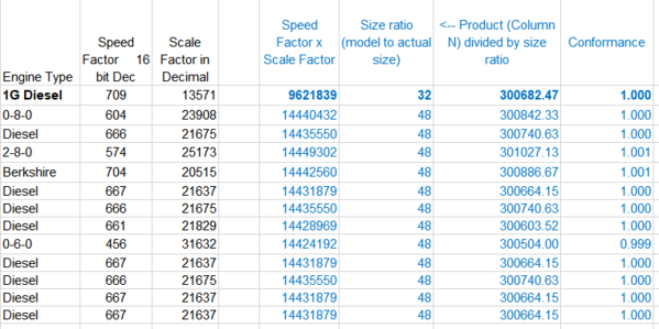
This SpdF value is converted to hexadecimal and loaded into RAM at addresses 0x04 and 0x05 (big endian). Again, we don't know what this value is used for but we know how to calculate. My equations match the actual value to within 0.05 percent.

Last edited by SanDiegoMark

Ok after looking at the spreadsheet, here's what I came up with...  The "speed factor" and the "scale factor" have a dependent relationship.  I'm not sure which one is derived from the other, but there's an inverse relationship between them, and they both ultimately relate motor RPM (or stripe count) to distance traveled.  Multiplying the two values together produces the same value with one notable exception (see table below)

The exception is the G-gauge diesel, and the missing element is what I'll call the "size ratio."  In other words, O scale is 1:48 actual size.  G scale (at least as produced by MTH) is 1:32 actual size.  When you take the product of the speed factor and the scale factor, and then divide by the size ratio, everything lines up to within 1%. 

In practice, I would imagine that varying tire thicknesses, possible errors in the stripe count caused by overlapping tape, variations in the diameter of the flywheel affecting count accuracy, sensor distance to the flywheel, etc., may contribute to more than 1% error.

Attachments

Images (1)
  • mceclip1

Ted,

I completely missed the point that the G scale diesel was 1:32 not 1:48.  That's why I like to post this stuff, gets more eyes looking at it. Thanks.

I'm guessing that the Scale Factor, the Speed Factor and the Chuff Factor are all based on wheel diameter, tach stripe count and gear ratio. Then Scale Factor adjusts the DTO and DOD counters while Speed Factor adjusts the motor speed. And Chuff Factor adjusts the smoke fan.

Add Reply

Post
The DCS Forum is sponsored by

OGR Publishing, Inc., 1310 Eastside Centre Ct, Suite 6, Mountain Home, AR 72653
800-980-OGRR (6477)
www.ogaugerr.com

×
×
×
×
Link copied to your clipboard.
×
×