
I'm looking at the MTH Operating Box Car with Signal Man, 30-7564, PRR "Road of the Turbine" livery.  The MTH product page (https://mthtrains.com/search/30-7465) has a video that says it operates anywhere on the layout with any transformer with a bell button, and also has instructions that say it works on an operating track section.  Can anyone tell me which (or both?) of these is correct?  The car has both slide shoes and a center pickup roller, I'd like to use it with a conventional layout, with a UCS track section powered by 14V accessory terminals, in other words the center rail won't necessarily have any voltage when the "unload" function of the UCS track is operated.  I'd like to understand how it will work before I buy one.  Thanks!

Original Post

Replies sorted oldest to newest

Very nice, thank you!  So, the mention of the bell button in the video is just nonsense I guess?  And what is the center rail pickup roller for?  Will it operate without power to the center rail?  I was thinking of this for a Christmas gift for one of my kids which is why I want to understand how it will work ahead of time.

I do not have one of these boxcars but I do have several of the operating signalman cabooses.  The cabooses come with the sliding shoes on each truck to  be used with the five rail control track BUT it operates beautifully any where on the tracks using just the bell button.

It is a really fun car to operate while the train is in motion wherever you want. 

I actually had to glue the pick up shoes in the up position to keep the caboose from derailing on some of my Atlas and Ross switches.

So, I suspect the boxcar you are looking at would most likely operate the same way.

Happy railroading,

Don

Last edited by DGJONES

Odd, the video sure seems to illustrate it working on a plain section of track.  However, I was looking at the video and it appears they have non-stop operating tracks on that stretch, look at the left track in this clip.  I see five rails and the uncoupling buttons strung out in a constant string.

Short answer is, no way of knowing from the conflicting information there what the capabilities are.

Attachments

Images (1)
  • mceclip0
bajinnova posted:

Very nice, thank you!  So, the mention of the bell button in the video is just nonsense I guess?  And what is the center rail pickup roller for?  Will it operate without power to the center rail?  I was thinking of this for a Christmas gift for one of my kids which is why I want to understand how it will work ahead of time.

You always need power to the center rail.  That is your +.  The outside rails are your -.

On the operating track you have a magnet in the middle and two inside rails.  When the magnet is energized, you can uncouple cars.  When the inside rails are energized, those shoes will make the car operate with the man coming out.

Ron

OK, this is confusing enough to make me want to get one to see how it works.  There shouldn't (in principle) be a need for center rail power, as the left and right control rails will have the same voltages as center to outside rail in original UCS wiring (where coil and and control rail voltage just comes from track power) -- I think at least some post-war operating cars had shoes but no roller.  But I was also curious about the claim that you only have to hold the unload button down until the car starts to operate -- that would make sense if it's using the control rails as a trigger but getting power from the center rail.

Thanks, Don, for your comment about the bell button on the cabooses.  Hopefully the box cars work the same way.

Ron045 posted:

Don.  What is the bell combination?  I am in conventional mode and can only operate the engine bell and not the signalman car.  In DCS mode, the transformer bell does nothing.

I operate my layout using a Lionel ZW-C.  I run TMCC/Legacy and DCS.  I can operate the signalman caboose using either the CAB 1 or 2 by addressing the TR number that is controlling the ZW output for the track the caboose is on and pressing the bell button or by pressing the bell button on the transformer.  Either one works and you only have to hold the button down until the man begins its cycle.  Once started the lantern lights and the man extends out the side stops for a few seconds and the returns to his default position and the light goes  out.

I have not tried using the DCS remote but I think it might only work if you had the track the car is on set up as VARIABLE so that when you address the TIU channel controlling the track your car is on and depress the bell button (just like you would do if using the TIU to control conventional engines).

I can see no reason why MTH would not use the same technology for the operating signalman boxcar.  I can however see why the unloading boxcar might only operated using the five track section.

I have always felt these cars and they way to control them is one of MTH's best kept secrets.

Don

Last edited by DGJONES

Folks, it will not activate using the bell button on the transformer like the caboose.  Why, I don't know but it's why I sold the premier version of the boxcar with operating signalman when it first came out.  It's a shame as I was looking forward to using it for some prototypical operations.

-Greg

Last edited by Greg Houser

I'm still trying to figure out the finer points of how to wire the operating track to make it work!

But, here's my conclusion so far:

The center rail power the motor that moves the guy inside & opens the door

The special rails start the process.. there's a circuit board inside that has a microswitch that will stop the action once it has gone thru a complete cycle.  There's a sliding arm that opens the door and is attached to an internal slide that pushes against the microswitch when the door is closed all the way.

So, it seems to me that the operating track section starts the process, but the train can move off that track and the sequence will continue (powered by the center rail) until the guy goes back in and the door closes.

I think...

bajinnova posted:

... But I was also curious about the claim that you only have to hold the unload button down until the car starts to operate -- that would make sense if it's using the control rails as a trigger but getting power from the center rail.

For the operating cars I've seen, the instructions say you must activate the car for about 2-seconds to start the self-completing cycle.  During the startup 2-seconds, the 4th & 5th operating rails supply power to a DC gearmotor which slides the door over a lever microswitch.  Once it passes the switch the power to the gearmotor is then supplied by the center rail.  The center rail continues to provide power to the gearmotor until the door returns over the lever microswitch and the cycle is complete. 

So it takes more than a momentary "trigger" to start the cycle.  In the middle of the video you can see/hear some "false starts" where the trigger was too short and the door did not slide over the microswitch.

As mentioned by others, the sliding-shoe pickups can present clearance issues with certain track systems.  In such a case a bell-detector circuit could be used to sense the DC offset voltage on the center rail and enable the gearmotor for ~2 seconds until the track voltage takes over to complete the cycle.  DIY DC-offset detector circuits are only $1-2 in parts and have been discussed in many OGR threads though usually for detecting Whistle/Horn.  But this does get you operation anywhere on the layout rather than just over a UCS or Operating Track section.

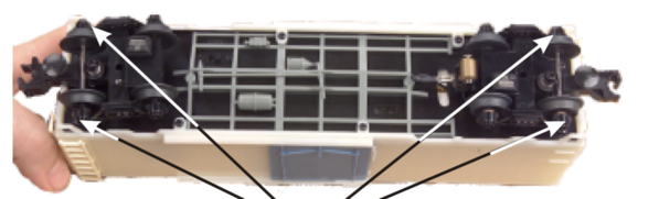
For that matter, for about $5 in parts, I've posted a DIY to use a wireless remote to provide the 2-seconds of startup trigger to activate the operating car anywhere on the layout.  The wireless remote has the advantage (over the bell method) in that you can uniquely address a specific operating car rather than all responding to a global bell command which would trigger all operating cars so equipped.  As I recall there was muted interest since it requires component-level assembly and soldering.  I dug up this photo of the components and a short video.  No 4th/5th rail operating shoes required.  All power comes from the center rail with only 3 wires patched in to the existing MTH circuitry.

reefer remote components

The video again demonstrates the ~2-second trigger needed to move the door over the lever microswitch which starts the self-completing animation.

Attachments

Images (1)
  • reefer remote components
Rigatoni Express Railroad posted:

... Are the three wires (White, yellow, Red) already in the car?

yellow-white connections

red connection

Not the physical wire itself - you have to supply 3 wires of several inches each and of course they don't have to be the color indicated.  I chose those colors to match the terminals where they attach to...which just happened to be solderable terminals (2 on the DC gearmotor, 1 on the microswitch) so you don't have to solder the wires directly to the MTH electronic circuit board.

gunrunnerjohn posted:

The only problem I see with the bell circuit is you also get the bell on the locomotive.

Right.  I figure this was back-in-the-day when getting a horn sound was a "luxury" option.  So I figure the horn was more popular than the bell so the bell detector would be a logical choice?  Of course in most cases when driving a local DC load, you simply reverse the 2 wires of the offset detector and a horn-detector becomes a bell-detector. 

Attachments

Images (2)
  • yellow-white connections
  • red connection

Add Reply

Post

OGR Publishing, Inc., 1310 Eastside Centre Ct, Suite 6, Mountain Home, AR 72653
800-980-OGRR (6477)
www.ogaugerr.com

×
×
×
×
Link copied to your clipboard.
×
×