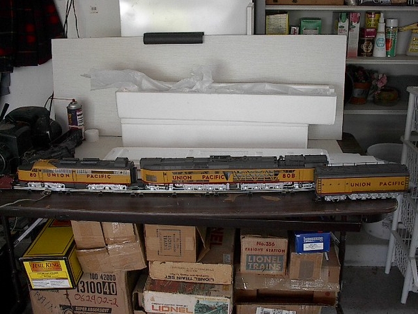
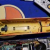
I have an MTH PS1 Gas Turbine 20-2124-1 that I am converting to ERR Cruise.  I am putting a cruise board in both powered units.  Sound will be in the A unit.  I plan to use the tether to run the rear coupler from the A unit ERR Cruise board.  The conversion has me asking the following questions:

1)  Can the smoke units be wired directly to the ERR Cruise board and not burnout due to excessive voltage - what voltage does the ERR Cruise board provide to the smoke unit?  If it needs a resistor in series what value should I use.

2)  The marker lights and cab light appear to be on a voltage regulator board.  What voltage are these lights - 6 volts and are they incandescent or led?   Can the voltage regulator board be wired to the ERR Cruise board at the light output?  The circuit board was connected directly to track power in the MTH setup.

3)  The PS1 headlight is connected to the motor diver board with a blue and yellow wire.  Is this bulb an led or incandescent?  Is this bulb 1.5 volts?  Can I wire a resistor in series to use this bulb or led with the ERR Cruise board, if so what value of a resistor should I use.

Thanks  in advance for any help given

Original Post

Replies sorted oldest to newest

Seen answers below in red.

Mark Girardi 121016 posted:

I have an MTH PS1 Gas Turbine 20-2124-1 that I am converting to ERR Cruise.  I am putting a cruise board in both powered units.  Sound will be in the A unit.  I plan to use the tether to run the rear coupler from the A unit ERR Cruise board.  The conversion has me asking the following questions:

Why not just run the coupler from the rear Cruise board, you accomplish the same thing without the tether?

1)  Can the smoke units be wired directly to the ERR Cruise board and not burnout due to excessive voltage - what voltage does the ERR Cruise board provide to the smoke unit?  If it needs a resistor in series what value should I use.

The Cruise Commander will support one of those smoke units, but not two.  If you want to control two PS/1 smoke units, you'll need to add a relay to switch the power, the relay will be powered from the Cruise Commander smoke output and it'll switch track power to the smoke units.

2)  The marker lights and cab light appear to be on a voltage regulator board.  What voltage are these lights - 6 volts and are they incandescent or led?   Can the voltage regulator board be wired to the ERR Cruise board at the light output?  The circuit board was connected directly to track power in the MTH setup.

You can wire them directly to the Cruise Commander headlight, or just leave them wired to track power.

3)  The PS1 headlight is connected to the motor diver board with a blue and yellow wire.  Is this bulb an led or incandescent?  Is this bulb 1.5 volts?  Can I wire a resistor in series to use this bulb or led with the ERR Cruise board, if so what value of a resistor should I use.

The bulb is a 1.5V bulb.  I use a standard 3mm flangeless LED with a 470 ohm resistor.  If you plan on running conventional with this, add a diode to the LED circuit.  If you want to just use an incandescent bulb, a 12V bulb is the proper size for the Cruise Commander output.

Thanks  in advance for any help given


John,

Thanks for the reply.

I have serviced the smoke unit and it puts out a ton of smoke at 18 volts.  Will the unit be able to withstand having 18 volts applied continuously from the ERR cruise board or will I need an inline resistor?  If I need the resistor, what value should I use?

How do I use the 1.5 volt headlight with the ERR cruise board?  What value resistor should I use?

Thanks Again

Never use resistors for this kind of function, remember a smoke unit is just a resistor with a lot of current going through it!  If you use series resistors, they get hot just like smoke units.   The Smoke output of the ERR Cruise board isn't 18 volts, it's half/wave rectified track power in command mode.  The PS/1 smoke units will run on 18V track power if you use a relay to control multiple units, they have an internal regulator.

I wouldn't bother to try to use the 1.5V bulb, but I'd have to know the current to compute a resistor anyway.  I'd use a warm-white LED, you'll get MUCH better lighting.

Mark Girardi 121016 posted:

I have an MTH PS1 Gas Turbine 20-2124-1 that I am converting to ERR Cruise.  I am putting a cruise board in both powered units.  Sound will be in the A unit.

I have to ask, which ERR TMCC sound set are you using?  Last I checked ERR doesn't have a gas turbine sound set, just the steam turbine.  I have the RK version I want to add TMCC to, but want sounds.

Once again thanks to John for all the help.  I have the A unit just about complete.  I just have to attach the antenna and close it up.  The holiday is slowing the project down, so sorry for the late reply.  The engine works great!  I will be moving on to the B unit later.  As far as sound, I could not find a prototypical sound for it.  ERR makes a dooblebug gas engine board, but I did not like the small gas engine sound.  I know this may annoy some people, but I installed a Dash 9 sound board.  I do have to say the original Protosound board was not so good, that coupled with the lack of command control, had the unit sitting and not being used.  I do have a question about the LED lighting.  The 3 volt LED I acquired works great when attached to a battery, but lights up for a second when the engine starts and stays off.  I wired it with a resistor inline, so I am not sure what the problem is with the setup.

Thanks Again 

I swapped the polarity of the LED and it worked.  Thanks for the help!  I was unable to get the feature post on the ERR board to function with the smoke unit so I wired the smoke unit to track power.  I followed the directions on the feature 8 function numerous times and was unable to get the unit to work.  It smokes now that I have directly wired to track power.  MTH had it wired directly to track power originally.  Do you thing 18 votls will be too much for it in the long run?

For using the feature output, you'll need to put a .01uf capacitor across the feature output to ground, then it will recognize the smoke unit.  The triac won't fire if it doesn't see a load, and the diode drop of the bridge rectifier on the smoke unit fools it into thinking there's no load.  The reason that LED's work on the lighting outputs is that cap is on the Cruise Commander for the light outputs.  If you ever convert a plain TMCC locomotive to LED lighting, you have to add that cap as well.

The reason I'd want the smoke powered that way would be so I could control it from the remote.

John,

Thanks so much for all the help.  I have got everything to work with your instructions.  I ordered .01 uf ceramic disc capacitors to use the feature output on the ERR board.  I wire the capacitor from the feature output to ground and then run the smoke unit hot connection from the feature output as well?  I hope theses basic capacitors are the correct ones?  I also had a question about smoke unit batting.  I serviced the smoke units and used tiki torch wick as batting.  Is this a good batting?

Thanks Again

Yes, if there ever comes around a way to use the PS1 sounds and have TMCC.  The turbine sounds in this and other MTH turbines I have are the only roadblocks to converting them to ERR CC.  Just a thought, is there anyway feasible to provide a variable load to the PS1/QSI board and "fool" it into thinking there is a can motor load and produce the original PS1 turbine sounds?  True, the sounds may not be under control of the cab1/etc..... but to have command control and original turbine sounds "in sync" would make a great difference on many good early MTH turbines.

Jesse   TCA

Mark Girardi 121016 posted:

John,

Thanks so much for all the help.  I have got everything to work with your instructions.  I ordered .01 uf ceramic disc capacitors to use the feature output on the ERR board.  I wire the capacitor from the feature output to ground and then run the smoke unit hot connection from the feature output as well?  I hope theses basic capacitors are the correct ones?  I also had a question about smoke unit batting.  I serviced the smoke units and used tiki torch wick as batting.  Is this a good batting?

Thanks Again

Yep, it's as simple as that.  I've used Tiki torch wick, but I don't like it as much as the braided wick I found on eBay that matches MTH wick.

texastrain posted:

Yes, if there ever comes around a way to use the PS1 sounds and have TMCC.  The turbine sounds in this and other MTH turbines I have are the only roadblocks to converting them to ERR CC.  Just a thought, is there anyway feasible to provide a variable load to the PS1/QSI board and "fool" it into thinking there is a can motor load and produce the original PS1 turbine sounds?  True, the sounds may not be under control of the cab1/etc..... but to have command control and original turbine sounds "in sync" would make a great difference on many good early MTH turbines.

Jesse   TCA

Jesse, it's been done, but not with cruise.  Both TAS and Digital Dynamics had products that interfaced with the PS/1 sound board to use the PS/1 sounds.  There's no easy way now that both of these outfits are defunct.  The problem is getting all the other sounds synchronized with TMCC, horn, bell, etc.  Also, since the voltage is always at maximum, any prime mover control is always looking like it's at notch-8, full throttle.

John,

The conversion to ERR went so well with the Gas Turbine I am looking to do a Coal Turbine MTH 20-2214-1.  This is a Proto1 engine as well.  The only difference is the Coal Turbine has a Mars light and three smoke units.  I assume the headlights are 1.5 volts?  Is the Mars light on the 6 volt constant voltage board with the marker lights and cab light?  How do I used a relay to control the second smoke unit in the B unit?  What make and model of relay do I use?  Do I need to wire a rectifier for the relay?  I assume the feature out on the ERR board will still be connected to a .01 uf capacitor?  I also assume the relay and other smoke unit would be connected to the the feature output?  My understanding is the feature output would provide a signal to the relay and the relay would switch the track power on to the second smoke unit.  I just need to know what parts (relay, rectifier, ect) to buy and the correct wiring?  You made this MTH conversion process so much fun with your assistance.  It allows me to use engines sitting in boxes.

Thanks.

Mark

I believe the MARS light and the headlights are all driven from a constant voltage board, the markers are probably on that as well.

For the smoke units, I'd find a 12V DC relay.  This RELAY GEN PURPOSE SPDT 5A 12V would do the job for three smoke units.  Connect the .01uf cap across the feature output, and then you need a series diode and a 100uf cap across the coil of the relay.  The diode is to make sure the momentary boost AC won't cook the cap.

The relay will be switching track power for all the smoke units.  If desired, since they're cheap, you could use another relay in the second unit and just run the low current coil drive across the tether.

John,

Thanks Again!  Much appreciated!  I have one other question.  What value diode (parts number if you could) and what direction do I wire the diode (cathode goes to what terminal on the relay (I assume the negative terminal).  I also assume the capacitor if it is directional will be wired negative to negative on the relay.  The B unit is the only unit with two smoke units, so I will only need a relay in that unit.  I will wire the A unit smoke unit to the ERR feature output in the ERR board in the A unit.

Thanks,

Mark

Well, the diode is only supplying the relay, so the common 1N4003 is more than sufficient, the cathode faces the relay, the anode goes to the feature output.  The + terminal of the capacitor goes to the cathode of the diode, the negative terminal goes to frame ground.  The relay is wired in parallel with the capacitor. 

Truthfully, I'd wire all the smoke units through relays, that way they will be consistent in operation and you're not putting any demands on the R2LC.

John,

I already had the .01 uf capacitors from Jameco.  Thanks again for all the help.  I plan to put a relay on the smoke units in the Gas Turbine to take the stress off the R4LC and then move onto the Coal Turbine. I may have some questions as I get into these projects deeper.  Thanks again!  You made these projects possible 

John,

I wired the relay circuit per my diagram.  The ERR feature output does not power the relay.  I programmed the ERR board with the AUX1 &# 8 selection for diesel and smoke.  I push AUX1 and #8 when I get the engine running and nothing.  I tested the relay with track power and the smoke unit functions.  Any ideas on what to do next.

Mark 

MTH 20-2178-1 U.P. DD40AXMTH 20-2185-1 UP Veranda #75MTH 20-2214LS U.P. 80 Gas TurbineMTH 20-2261-1 U.P. Propane Turbine no.57John,  Yes, I am familiar with the TAS and Digital Dynamics products, have in use one of the DD units.  Just looking to see whether there may be an alternative to achieve the same, would be a worth while endeavor.  Have the MTH DD40X to put under ERR control, as well as the MTH Veranda, looking to use the Lionel RS for these.  However, I saw where the Lionel Veranda RS4 was not listed as available, correct?   As for my Propane Turbine, the #80 Coal Turbine, etc....??  IMO these are all excellent models, and I do run them under Cab1 aux/9 for conventional, just to have them full TMCC would be better.      Your input and experience, along with your products I have used, are much appreciated.  May we all have a great and prosperous New Year.

Jesse

Attachments

Images (4)
  • MTH 20-2178-1 U.P. DD40AX
  • MTH 20-2185-1 UP Veranda #75
  • MTH 20-2214LS  U.P. 80 Gas Turbine
  • MTH 20-2261-1 U.P. Propane Turbine no.57
Last edited by texastrain
Mark Girardi 121016 posted:

John,

I wired the relay circuit per my diagram.  The ERR feature output does not power the relay.  I programmed the ERR board with the AUX1 &# 8 selection for diesel and smoke.  I push AUX1 and #8 when I get the engine running and nothing.  I tested the relay with track power and the smoke unit functions.  Any ideas on what to do next.

Mark 

Put a light bulb across the feature output and see if it's turning on and off.  What exact relay are you using, and how is it wired now?

John,

I used the relay you sent me the link to in this long post.  I wired it exactly like we discussed last night in the diagram I posted.  I disconnected the relay and wired a .01 uf capacitor to ground from the feature output and also connected a 3 volt led with 470 ohm resistor.  I get nothing when I press AUX1 & 8.  It appears the ERR board may be defective.

All that's on the Cruise Commander is a trace from the socket to the feature connector, stick an ohmmeter on it and see if they're connected.  Truthfully, I'm having a little trouble believing it's the Cruise Commander.  Here's the bottom of the board, there's a short fat trace between the R2LC smoke pins on the socket and the feature output connector.  That's it!  Funny thing, I notice that the smoke already has the .01uf cap, but the front light seems to be missing the cap for the triac, maybe it's somewhere hidden on the board.

Attachments

Images (1)
  • mceclip0

I don't know what's going on at this point as I can't imagine the Cruise Commander board having that trace gone.  Maybe a bad connector for the feature connection?  Check continuity from the R2LC socket all the way to the wire that's connected to the feature output.  Also, make sure the R2LC actually works with smoke in the other location, maybe a short to ground is killing them as you put them in!

John,

I am about done installing the new DC Commander.  I will test the 12 volt incandscent bulb once it is assembled.  If the bulb works, do I need the additional .01 uf capacitor on the relay?  The DC Commander has a .01 uf capacitor on it.  It appears I only need the 100 uf capacitor on the relay circuit.  I will advise later if the new board and R4LC solve the problem.

Thanks,

Mark

John,

I thoroughly tested the DC Commander with a multimeter upon removal.  The traces are in tack and I get full continuity on the smoke output.  I examined the new DC Commander and the R4LC fits better on it than the board we removed.  I tried a couple of different R4LC units on the board in question before I removed it and noth worked.  I figure if it is apart, why not put in a new board.  

John,

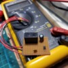
Thanks so much for all the help.  The new ERR board and R4LC worked.  I do not know why.  My guess is the first ERR board had a problem seating the R4LC.  The new ERR board seated the R4LC much better.  I finished the Gas Turbine completely.  Both units smoke units work via remote.  I have full directional lighting and coil couplers on both ends.  I have attached a picture of the relay board I built.  I put one of these relay boards in both units.  The smoke units put out a ton of smoke.  MTH is known for their high smoke output.  The remote control is a necessity with this monster engine.  Do you feel these smoke units will last running at a constant 18 volts?

Attachments

Images (1)
  • Relay Unit
Videos (1)
Gas Turbine

Well, it cuts the full-wave to half wave, so it reduces the voltage available a significant amount.  You can also add several more series diodes to further "tune" the smoke output if it's still too much.

Here's an eBay listing for a US seller with fast shipping, $2.95 for twenty 3A diodes, plenty to tinker with.  eBay: 182682754965

Attachments

Images (1)
  • mceclip0
texastrain posted:

Yes, if there ever comes around a way to use the PS1 sounds and have TMCC.  The turbine sounds in this and other MTH turbines I have are the only roadblocks to converting them to ERR CC.  Just a thought, is there anyway feasible to provide a variable load to the PS1/QSI board and "fool" it into thinking there is a can motor load and produce the original PS1 turbine sounds?  True, the sounds may not be under control of the cab1/etc..... but to have command control and original turbine sounds "in sync" would make a great difference on many good early MTH turbines.

Jesse   TCA

One way to get turbine sounds is use the Railsounds Lite board from a Legacy PRR 6200 turbine along with an RCDR receiver. Give it the same ID as your engine. It appears the RS4 boards from the TMCC version of this engine are sold out. Cost would have been about the same anyway.

Pete


Norton, thank you.  May have to give this a try.  But, still wish to find a way of using the original PS1 sounds of my MTH turbines.  It has been done in the past, TAS and DD, and I in use one of the DD units.  Seems, to me, if one can feed the necessary signal (even by induction signal or false generation) to the PS1 board, use of the PS1 sounds may be possible.   I am no electronics whiz, just basic knowledge and a "parts changer" IMO, but what of the idea of making use of the EMF signal off the ERR board to drive signal for the PS1 sounds?  Just thinking......

Jesse   TCA


Last edited by texastrain

Not a stupid question Mark, but resistors are the same as smoke unit heaters, do you really want to be generating enough heat for a smoke unit outside the smoke unit?  The diode is simply blocking half the AC waveform, it's not dissipating a bunch of heat to do the job.  The extra diodes each drop about .7 volts, independent of the current, so they're predictable as to their effect.  A resistor will drop voltage dependent on the current flow, not a good application here.

texastrain posted:

Norton, thank you.  May have to give this a try.  But, still wish to find a way of using the original PS1 sounds of my MTH turbines.  It has been done in the past, TAS and DD, and I in use one of the DD units.  Seems, to me, if one can feed the necessary signal (even by induction signal or false generation) to the PS1 board, use of the PS1 sounds may be possible. 

The DD and TAS units had complete control of the motor and thus controlled the sound as well.  You won't have that with just sky-wiring it in with a different system.

John,

At .7 volts per diode, I will probbaly need to string 7 or 8 together to drop the voltage to around 12 - 13 volts.  My understanding of the Proto 1 smoke unit is it ramped up smoke output based on track voltage, so at 18 volts it is really smoking a ton, as my video shows.  The Proto 1 engine would have been running at about 10 - 12 volts normally, so I may need to string 10 together.  I can line them up on a small perf board and mount the board in the engine.  This will make the units much more manageble on smoke output.  Thanks again!

If you think you need 7 or 8 to drop the voltage, you don't fully understand them yet!   The diode is a one-way valve, so the first one is cutting the power basically in half as it's only letting the positive half of the AC waveform through!

A Zener diode is also not the answer, it's really used as a voltage regulator in conjunction with a dropping resistor.  However, it would present much of the same issues as you'd see with a resistor in this application.

You're overthinking this, just use the diode(s).

Last edited by gunrunnerjohn

John,

I will use the diodes.  I planned to use them, as I ordered them right away earlier today.  I will work with them as soon as I get them.  I will measure voltage output at the input of the smoke unit to determine how many will be correct.  I will probably have questions as I experiment with them, once I get them.

Thanks Again,

Mark

John,

If you are running two smoke units off of one relay how are the diodes wired into the circuit?  Will one set of series wired diodes drop the voltage enough to power both smoke units or will I have two separate wires off of the relay with diodes in series off of each wire for each smoke unit?

Thanks,

Mark

John,

ERR by 3rd rail sells fat boy speakers.  Can the fat boy speakers they sell be used with the Railsounds boards they sell without any additional modifications - just plug in to the board like the lesser speaker they provide with the kit.  I believe the fat boy speaker is a different ohm rating the the basic speaker they send with the Railsound kit.

Thanks,

Mark

John,

Thanks for the info on the fatboy speakers.  It is very helpful.  I thought I would share my observation with the MTH gas turbine speaker.  I did a comparison between the basic ERR speaker (8 ohm) and the existing MTH speaker and found that I liked the larger MTH speaker better and kept it.  I have not tried the ERR fat boy speakers yet.  I just got a few in the mail.

Thanks Again,

Mark  

John,

I installed one diode and found the smoke output to be much improved.  Would I be correct in saying the the voltage dropped from 18 volts to 9 volts with the single diode?  I assume with each additional diode it would drop an additional .7 volts.  I found the output to be good on my test track with an LW transformer.  When I switched to the layout, where I use ZW-L transformers, I found the smoke output to be a little more than on the LW at the test bench.  Is the ZW-L that much more powerful that I would notice stronger smoke output?  What is the optimal voltage for the MTH smoke unit?  I may add another diode.  

John,

I finally succeeded with the Gas Turbine.  All the advice you gave me worked!  I finished it off with four diodes on the smoke units.  It now works perfectly.  Thanks!  I have another question.  I am doing a Coal Turbine now and the A unit has small lights inside the shell.  There is a spring attachment where the shell meets the frame for the power to transfer.  The wires are black and red at the point on the frame where the springs touch, which match the hot and ground from the pickups and axles.  These lights come on with the market lights and mars light.  Do you feel these grain of wheat size bulbs run off the constant voltage lighting board?  I have attached a picture of the shell.

Mark

Attachments

Images (1)
  • Coal Turbine

gunrunnerjohn posted:

They run off 6V, but they'd need a dropping resistor, which is normally on the CV board for the LED socket.

John, Your repeating what I said, but it is not on the CV Board in this case.  Looking closely at your picture you can see the yellow connector with red and black wires on the side of the bottom board.  In this case MTH used the PS-1 bottom board marker connection.   You do not have a marker connection on  that CV Board.  You just have 6V outputs.  That is why I said you should trace where the leads go.

For a TMCC conversion where the PS-1 board comes out, yes, you can tap off the CV board.  You can use the LNB or IL plug since these are constant on, not directional.  Solder leads to the bottom pins, but install a 100-150 ohm resistor in line with one of the leads.  Send it back to the pad keeping Red +DC and Blck -DC and you will have markers lite and the ability to remove shell without having to unplug light connector.  G

There's a socket on the CV board with a dropping resistor for marker/class lights if the unit is equipped with them.  They can, as George says, also be connected to the output on the PS/1 board, the yellow connector.  Easy way to find out, trace the wires from the spring contacts on the frame to where they go.  I'd guess the PS/1 board for this one as I don't believe that particular lighting board has the LED driver socket, the ones I have are all either MARS, headlights, or cab lights/number board outputs.  All the bulbs are 6V.

GGG posted:

gunrunnerjohn posted:

They run off 6V, but they'd need a dropping resistor, which is normally on the CV board for the LED socket.

John, Your repeating what I said, but it is not on the CV Board in this case.  Looking closely at your picture you can see the yellow connector with red and black wires on the side of the bottom board.  In this case MTH used the PS-1 bottom board marker connection.   You do not have a marker connection on  that CV Board.  You just have 6V outputs.  That is why I said you should trace where the leads go.

For a TMCC conversion where the PS-1 board comes out, yes, you can tap off the CV board.  You can use the LNB or IL plug since these are constant on, not directional.  Solder leads to the bottom pins, but install a 100-150 ohm resistor in line with one of the leads.  Send it back to the pad keeping Red +DC and Blck -DC and you will have markers lite and the ability to remove shell without having to unplug light connector.  G

Yep, I got there George, just slower than you did.   I just checked and those boards indeed don't have any marker outputs.  I'm more used to the CV boards used in steamers as that's where most of my work seems to gravitate.

Add Reply

Post

OGR Publishing, Inc., 1310 Eastside Centre Ct, Suite 6, Mountain Home, AR 72653
800-980-OGRR (6477)
www.ogaugerr.com

×
×
×
×
Link copied to your clipboard.
×
×