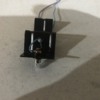
So I’m hooking up a steam light/smoke unit bracket (see picture) for a RailKing Mikado 30-1164-1.

Someone that owned it before me cut the wires to the bracket (as well as removed the 8 pin board connector and bulb) and the market lights no longer work. I soldered in a spare headlight wire harness I had from a RailKing 2-8-0. I know the colors aren’t original, but I’m concerned about the polarity.

Before I hook this up wrong and blow up my board, I want to know which wires connect to where. The red connector will be cut off the and wires soldered to wires coming from the respective pins on the board.

I know the marker light was on the ditch connector based off looking at the soft key layout for the sound file in ADPCM player. I also know from looking at ps2 wiring diagrams here on the forum that one wire goes to the 12 pin connector and the ditch connector comes from the 8 pin connector. If that’s wrong, please correct me.

In case the picture is hard to see, the two wires I soldered are light blue and dark purple.

Edit: I also checked continuity with my multimeter and there are no shorts between the two wires.

Attachments

Images (3)
  • 7E6012EC-CA68-4E83-AF9A-B847D353B224: The two wires I soldered in
  • 522F61E7-30EE-4602-BC4E-B4F082AEA17D
  • E3877D71-2EB7-4FAA-9CA2-7EA60403FB69
Last edited by jaketrainz
Original Post

Replies sorted oldest to newest

If neither of the wires are going to the frame, you're good with either polarity, it's an incandescent light bulb, it doesn't know from polarity.  If either wire is grounded, you have to fix that first, both MUST be isolated from the chassis.

No continuity between the bracket and either of the wires means I’m good, right? I checked that as well and all appears to be good.

Edit: Just cut off the connector and stopped the ends of the wires. I tested it with a AAA battery and got a dim glow out of the bulb.

Last edited by jaketrainz

So I ordered a wiring harness from MTH with an 8 pin 5v connector with a single wire coming off pin 3. From wiring diagrams, I've read this is the ditch 1 connection and I know the marker lights are on the ditch connector from looking at the engine's sound file.

I spliced and soldered the wires appropriately and checked continuity and all looked to be good with no shorting to the chassis. When testing however, nothing. The engine still turns on just fine and everything else works, but the bulb for the markers will not light up, even when turning off and on the LMK softkey. I tried two separate 6v bulbs and re-checked the continuity of the bulb socket and the wires and all is still good.

What may I be doing wrong? The board is a 3v PS2 board with 5v connectors. Are these boards any different by chance as far as pinout goes?

Add Reply

Post

OGR Publishing, Inc., 1310 Eastside Centre Ct, Suite 6, Mountain Home, AR 72653
800-980-OGRR (6477)
www.ogaugerr.com

×
×
×
×
Link copied to your clipboard.
×
×