
I have a MTH Z 500 transformer that I was going to give to a friend but I noticed a problem with it.  As soon as I pug it in it puts out 18 Volts even with the knob turned off.  I thought it may be the photometer or whatever you call it that controls the voltage but even after removing it it still puts out 18 volts. Has anyone had an experience like this or might possibly know what is wrong. Any help would be appreciated.

Original Post

Replies sorted oldest to newest

You should be able to open the Z-controller via 4 Phillips screws.  Takes just a minute.

Once open, I figure it will look like this -  a Z-750 controller but it ought to be similar.  Front and back:

z750 controller guts

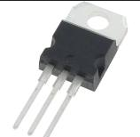
It's not clear to me if you absolutely must remove the aluminum heat-sink plate to access the 3-pin triac (circled in red).  But if so, that requires unsoldering the 3 wires going to the adjustment potentiometer (red rectangle).

Then, as suggested, read off the lettering on the triac and order a replacement.  A triac of this ilk should be, say, $1-2.  You'll pay more for the shipping unless you find it on eBay and wait a couple weeks for it to come from Asia.  Unless someone comes forward with the exact part #, just post whatever lettering you find and one of us will extract the relevant numbers to tell you exactly what to order.

As for the diodes, perhaps someone can identify exactly which diode goes bad.  I count about a dozen diodes on the circuit board.  It appears there are only 2 types of diodes - 1N4002 and 1N4148.  These part numbers are labeled on the board.  These a ~5 cent parts.  Again, you'll pay more for shipping than for the part and both these parts are on eBay where they are a couple pennies each though you'll need to pony up 99 cents to get a "lifetime" supply since you apparently need only 1.

So to answer you question, I'd say "yes" it's worth your time to take it apart, identify the triac part number, order a replacement, and attempt a DIY repair before giving it to your buddy.


Attachments

Images (1)
  • z750 controller guts
Last edited by stan2004

Or a later version! ** Your board shows surface-mounted components (vs. through-hole components on my photo) which usually comes later.  Can you post a photo of the other side of the board?  I wonder if you'll see another pair of those devices on the other side; for example, the MTH TIU variable channel uses such a multi-transistor design instead of a triac. 

In any event, if you already ordered parts, for the record what did you get?

** Note.  It appears the current version of Z controllers labeled ZCONTROLLER  are universal to the 50, 75, or 100 Watt brick transformers.  As opposed to earlier versions labeled Z-XXX which imply a mating to the brick of corresponding wattage.  I suspect it's the earlier controllers that use the single-triac design while the later version is what you have and use an alternative design.

zcontroller


bbsfdl60 posted:

I have seen this many times, there is a single diode on the board that needs to be replaced.  The MTH part number is BB-0000057.

 As for the diode, I do not see this part in my Z-750 controller so perhaps applies to the newer ZController.

tvs

The MTH site suggests the generic part number is 1.5KE51CA which is a TVS or surge-suppression diode - widely available for 50 cents or so.

Attachments

Images (2)
  • zcontroller
  • tvs
Last edited by stan2004

This thing cannot be repaired, as I don't know how they did it but the two triacs are part of the PCB and cannot be removed except for cutting or grinding them off.  I did just that but I think I damaged it to badly to repair I went to low and grounded off some of the silver on the PCB on one side and the other side I will have to mount it on top of what I have grounded down. If this is just to dissipate heat then I could solder some foil to the part I messed up. I will let you know in a couple of days when I replace the parts what happens. Luckily I am in a separate garage that is away form the house so I won't burn it down.  I will also post a pic of the other side when I get home from work.

RRaddict2 posted:

This thing cannot be repaired, as I don't know how they did it but the two triacs are part of the PCB and cannot be removed except for cutting or grinding them off.

Those components should be remove-able albeit a PITA.  I believe those are so-called DPAK surface-mount packages like this:

DPAK

First de-solder/lift the two legs from their pads.  Then place your iron tip along the length of the tab and wait say 5-10 sec, it will melt the solder joint on the back of the package and the body will lift off the board.  Obviously the large "silver" area of the board acts as a heat sink stealing the heat from the iron making the job more difficult.  Your board might be salvage-able though I'm thinking some kind of solder-able thin copper foil might be involved instead of non-solder-able aluminum foil.

Yes, I'd like to see a photo of the other side of the board.

And, for the record, what part numbers did you order?

Attachments

Images (1)
  • DPAK

Add Reply

Post
This forum is sponsored by MTH Electric Trains

OGR Publishing, Inc., 1310 Eastside Centre Ct, Suite 6, Mountain Home, AR 72653
800-980-OGRR (6477)
www.ogaugerr.com

×
×
×
×
Link copied to your clipboard.
×
×