
Several months back I posted an adjustable output voltage regulator board based on the LM317T IC, here. A few days ago I was contacted offline by a gentleman who wanted the same board, but narrow; only 1/2" wide. I made a version for him and ordered a dozen of them shipped to him direct. I thought I might as well post the build files here in case others may have need for an extra narrow regulator board. Costs are about $5.00 each for all domestic boards and parts; or about $1.00 each for offshore components.

Here is the circuit and a 3D depiction of the completed board. It uses all the same components as the previously posted board, above. The circuit is identical.

Circuit Snip

Top Front 3D View

The User Notes in pdf form and Gerber zip file are attached below. The BOM is identical to the earlier board.

Have fun, Rod


Attachments

Last edited by Rod Stewart
Original Post

Replies sorted oldest to newest

TedW posted:

Rod, looks good.  How long is the board in this configuration?  BTW  Thx for all your time and trouble on these pcb applications.  😉

Hi Ted. The board is 45 mm long, about 1-3/4". Sorry I did not include that in the description. To be clear, its exactly the same board as the earlier post circuit-wise, just narrower, which may help in some folk's applications. 

Rod

Rod, after linking back to earlier LM317 threads there is the dangling participle of isolated AC vs. DC ground.  Does the 3-D rendering function allow you to "install" a 2-cent 1N400x diode into 2 of the 4 bridge pads (AC to +) and, say, a jumper wire between the other 2 bridge pads (other AC to -)?  This would allow the same board to be used for 1/2 wave rectification where the AC and DC grounds would be the same which can be handy in some rolling stock applications.  This can also be handy in track-side applications making it directly compatible with insulated-rail triggering.

Separately, I may have missed it but I didn't see discussion of using the LM317P insulated package which would allow you to bolt the LM317 directly to the chassis/frame from heat management. 

IMG_5820

That is, finding those insulating washers and related hardware pieces can be a nuisance.  The insulated package is harder to find but can be expedient albeit at a price.  You can't get a whopping deal on eBay as you can with the LM317T (metal tab) for less than a dime.  While there are several eBay sellers of the insulated package, this may be the rare case where buying from DigiKey is cheaper! 


Attachments

Images (1)
  • IMG_5820
Last edited by stan2004

FWIW, no extra components required, just a set of jumpers.  I just use one of the diodes in the bridge for the half-wave option.  Here's how I did a switchable board, in this case this is mated with an eBay switcher to provide power at greater efficiency than linear regulators.

__000000

This is the board and the regulator board sandwiched below it.

Attachments

Images (2)
  • __000000
  • mceclip0
stan2004 posted:
That is, finding those insulating washers and related hardware pieces can be a nuisance.  The insulated package is harder to find but can be expedient albeit at a price.  You can't get a whopping deal on eBay as you can with the LM317T (metal tab) for less than a dime.  While there are several eBay sellers of the insulated package, this may be the rare case where buying from DigiKey is cheaper! 

That's true Stan, Digikey and Mouser have them for less than a dollar in quantity one, I didn't find one cheaper on eBay or places like Aliexpress.com

gunrunnerjohn posted:

FWIW, no extra components required, just a set of jumpers.  

IIRC, we had this discussion a few years back.  I believe if all 4 terminals of the bridge are soldered-in, you have to cut trace(s) on the board?  OTOH, if you know ahead of time that you want half-wave rectification for common-ground operation I think you can "simply" bend up one or more terminals of the bridge and solder less than 4 terminals.  Then add a jumper or whatever.  The point being cutting a trace with an x-acto knife or whatever is a bother.

In any case, the idea is to document these options, alternatives, etc. in the same spirit that the guys are consolidating the various PCB projects.

I was curious if these 3-D renderings allow you to "install" a 2-terminal diode into 2 of the 4 terminals of the bridge and show what it would look like.  Or, for example, to cut off or "bend up" one or more terminals of the bridge rectifier and show what it would look like installed. 


Stan, I added the jumper field to solve any cutting issue.  That allows me to build the board with both capabilities and just jumper it for the desired operation.

There's a little fooling around to try to graft components in that aren't in the design.  I suppose it could be done, but I'm not sure how much effort it would be.  I think the way to do the resistor substitution would likely be just change the 3D file to a resistor and then try to position it.

Stan; thanks for these two very good ideas. You are the master of timely helpful suggestions! 

I actually have in my user notes that the grounds must be kept isolated, and that if the supply is DC you can just jumper the bridge rectifier pads. But I never considered the idea of adding a simple diode to the + side and jumpering the ground side to achieve common-grounded half wave rectification. Think I'll go back and add that to the user notes.

The insulated 317P is also a nice option. I checked Digikey and they can be had for less than $1, compared to anywhere from $3 to $5 each, and more, on ebay. So definitely DK is the way to go. I'll also add that to the user notes.

Thanks again for your valuable input! 

Rod

stan2004 posted:
gunrunnerjohn posted:

FWIW, no extra components required, just a set of jumpers.  

IIRC, we had this discussion a few years back.  I believe if all 4 terminals of the bridge are soldered-in, you have to cut trace(s) on the board?  OTOH, if you know ahead of time that you want half-wave rectification for common-ground operation I think you can "simply" bend up one or more terminals of the bridge and solder less than 4 terminals.  Then add a jumper or whatever.  The point being cutting a trace with an x-acto knife or whatever is a bother.

In any case, the idea is to document these options, alternatives, etc. in the same spirit that the guys are consolidating the various PCB projects.

I was curious if these 3-D renderings allow you to "install" a 2-terminal diode into 2 of the 4 terminals of the bridge and show what it would look like.  Or, for example, to cut off or "bend up" one or more terminals of the bridge rectifier and show what it would look like installed. 


I think if you know ahead of time that you need a common ground, the easiest thing to do is leave the bridge out, put a diode across from the near ac connection to the #1 pad (+), and a jumper from the other ac connection to board ground. Presto, done. No trace cutting, no bending, no muss, no fuss! 

Rod

I realize the train has left the station, but two other comments for the record.

lm317 pcb ideas

1) Will a 3296W trimpot physically fit in the space allotted for the 3362P - without bumping into the cap or bridge?  It's a little longer/wider and it would require a new pad to be dropped on the board since the terminals are in-line albeit on a 2.54mm grid.  The idea is to allow either style of trimpot to be inserted.  The 3296W is multi-turn as used in the ubiquitous LM2596 stepdown regulator modules that we have come to know and love.  Same cost on eBay when I just looked. This might be a nice project for someone getting started with DipTrace and could take Rod's existing design and make a minor modification with a high likelihood of success while contributing to the cause (in my opinion of course).

2) For some applications with low-current, it might make sense to install the TO-92 version of the LM317.  Might be even cheaper depending on where you buy.  The idea here is very few designs come anywhere near requiring the >1 Amp capability of the LM317T.  In fact I seem to recall real-user data where the current required in a passenger car LED application was 5 mA (or less)!  In such a case there's no need for the TO-220 version which of course is a rather large package.  Commensurately, you would not need a 1000uF capacitor to achieve a suitable flicker reduction...and could use, say, 220uF or less which would allow even a smaller overall space requirement.  Again, the idea here is to create what amounts to an Application Note for Rod's board design.  I suppose if someone learning DipTrace wanted a simple modification project to get one's feet wet, they could add 3 pads on a closer grid to install either the TO-92 package or the TO-220 package (same PCB board)...and contribute to the cause (in my opinion of course).

Attachments

Images (1)
  • lm317 pcb ideas
Last edited by stan2004
stan2004 posted:

2) For some applications with low-current, it might make sense to install the TO-92 version of the LM317.  Might be even cheaper depending on where you buy.  The idea here is very few designs come anywhere near requiring the >1 Amp capability of the LM317T.

I did a fixed voltage version using the TO-92 chip. 

It's less than an inch long and .3" wide.  You can use any voltage three-terminal regulator in the board to pick a voltage.  You can also stick the CL-2 constant current regulator in the board with no changes for a constant current application like LED lighting.

Attachments

Images (1)
  • mceclip0

Bob, the heat sink is up to the end user, and will vary by application.

John, the space between L1 and the pads is to permit the use of connectors like the small green 2.5mm screw terminals. For the final run I did in fact shorten the board a little, it is about 1-3/4" long.

I do like the idea of the additional diode pad under the D1 pattern; will likely add that to the design. 

We need to remember that one of the objectives here was to stick with easy thru-hole design so that most folks (like me) can build it without too many issues.

Rod

Come on Rod, live a little!   Gosh, I'm 76, and if I can stick SMT parts on a PCB, I think there should be lots of folks that can manage it as well.

The major reason I use SMT stuff is I'm usually trying to make something I'm going to stick inside a locomotive or rolling stock.  It always seems I don't have sufficient space, so I try to make them as small as possible.

stan2004 posted:

I realize the train has left the station, but two other comments for the record.

1) Will a 3296W trimpot physically fit in the space allotted for the 3362P - without bumping into the cap or bridge?  It's a little longer/wider and it would require a new pad to be dropped on the board since the terminals are in-line albeit on a 2.54mm grid.  The idea is to allow either style of trimpot to be inserted.  The 3296W is multi-turn as used in the ubiquitous LM2596 stepdown regulator modules that we have come to know and love.  Same cost on eBay when I just looked. This might be a nice project for someone getting started with DipTrace and could take Rod's existing design and make a minor modification with a high likelihood of success while contributing to the cause (in my opinion of course).

2) For some applications with low-current, it might make sense to install the TO-92 version of the LM317.  Might be even cheaper depending on where you buy.  The idea here is very few designs come anywhere near requiring the >1 Amp capability of the LM317T.  In fact I seem to recall real-user data where the current required in a passenger car LED application was 5 mA (or less)!  In such a case there's no need for the TO-220 version which of course is a rather large package.  Commensurately, you would not need a 1000uF capacitor to achieve a suitable flicker reduction...and could use, say, 220uF or less which would allow even a smaller overall space requirement.  Again, the idea here is to create what amounts to an Application Note for Rod's board design.  I suppose if someone learning DipTrace wanted a simple modification project to get one's feet wet, they could add 3 pads on a closer grid to install either the TO-92 package or the TO-220 package (same PCB board)...and contribute to the cause (in my opinion of course).

Good suggestions Stan; my take for what it's worth:

1) I haven't tried to implant the 3296W trimpot, but may give it a whirl. IMO the readily available 3362P pots are nice and compact, and offer only a 270 deg turn from max to min, and will allow 0.1 volt output resolution in this circuit, so that's what I went with, for now! That's only me though.

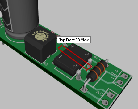
2) This board was not really intended for low power apps like led lighting. Grj's constant current board already does a great job of that. This board was intended for GP vreg use up to about 500 ma, AC or DC input, engine, car, or trackside mount. Having said that I tried adding the TO-92 pattern, as well as grj's suggestion of a single diode pattern over the bridge diode pattern. Here is what I came up with:

Vreg Narrow R2.21 Snip

This is certainly workable, though I had to scrunch the components a bit to kept the new length down to 48mm, just under 2". But it fits and it would work. Width is still 1/2". I used a DO-35 pattern for D2 and angled it as you see to take up less space. 

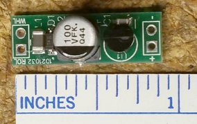
But then I got thinking, is this really necessary? The TO-92-100 pattern has the same pad spacing as the TO-220, and the pinouts are the same. So why not just stick the TO-92 leads into the same holes and call it done? Sure, the TO-220 drill holes are bigger than needed for the small version, but no big deal. Then I tried doing this fit and a 1N4002 diode across the ~ and + pads of D1. Here is the mock up:

IMG_1592

As you can see, it's a no-brainer fit. This of course is not the same board as posted above, but you get the idea. For a low power 317L version, you could just use a 1N4148 diode for D2, which would be even easier to fit.

I see 4 power options available in using just the bridge diode pattern as it stands:

1) Full wave AC to DC, with isolated grounds, using the bridge diode.

2) Half wave AC to DC, with common ground, using a diode as pictured, and a wire jumper from ~ to -.

3) Straight DC input using jumper wires for both sides of the bridge pattern, as per 2).

4) Straight DC input with the bridge in place, accepting that there will be a 1.4 volt loss in feed voltage to the 317. 

This is pretty good versatility. All in all, I really don't see a burning need to put yet another set of Gerbers out there, but that's only my opinion of course!! If we think it should be done, by all means I will put them here for rtr12 to add to the sticky post of build projects. 

Rod

Attachments

Images (2)
  • Vreg Narrow R2.21 Snip
  • IMG_1592
gunrunnerjohn posted:

Come on Rod, live a little!   Gosh, I'm 76, and if I can stick SMT parts on a PCB, I think there should be lots of folks that can manage it as well.

The major reason I use SMT stuff is I'm usually trying to make something I'm going to stick inside a locomotive or rolling stock.  It always seems I don't have sufficient space, so I try to make them as small as possible.

Well you've got a couple of years on me John; but you must have a way higher level of patience than me! 

Not to mention better eyesight, haha!

Rod

But wait!  There's more!  

Given the compact size of this board, it reminds me of a $1 module you can get on eBay that is essentially just a bridge rectifier and capacitor.  OK, there's an LED but ignore that for a second.  The idea is Rod's board can be used to perform the useful task of AC-to-DC conversion with large capacitance on the DC side.  And of course it has the DCS choke which I can't imagine any eBay module would ever have!

bridge and cap for 75 cents

So if compiling a book called "101 things you can do with Rod's board":

1) there are thumbnail sized mini DC-to-DC modules though some are limited in their allowed input voltage range.  If, say, driving a smoke unit in a diner car or caboose, you need at least 5 Watts of power at maybe 5V or 6V  DC.  Because the LM317 is a linear regulator, it might be overwhelmed by the heat dissipated going from 18V AC track voltage down to 5V DC.  So you can set the LM317 to, say, 20V DC and then pair it with a mini DC-to-DC module to efficiently reduce the voltage to 5V DC.

2) or if a car is used in both conventional and command environments, the AC-to-DC converter could be paired with a buck-boost DC-to-DC module for constant voltage lighting.  Most of the buck-boost modules do not have enough input capacitance to support flicker free lighting so that's where the capacitor on Rod's board comes to the rescue!

3) though probably not for rolling stock, but one could choose not to install the LM317 in Rod's board and simply use the board for the AC-to-DC bridge and capacitor and pair it with a DC-to-DC LM2596 voltage regulator with built-in voltmeter.  It has come up several times that there are no low-cost AC-to-DC stepdown voltage regulator modules on eBay WITH integral voltmeter.

And so on!

Attachments

Images (1)
  • bridge and cap for 75 cents

Rod is helping me. I needed a small board.

My question Stan brought up. Is ground. So dc and AC can use same ground?.

On the half wave. Which I'm using.  Once I get the boards so I can see where things go my plan is to jumper AC in to + of bridge. With a diode.

Then jumper - of bridge to dc neg. A.c. ground will share common ground.

When using fixed resistors. Do you leave one hole open? No jumper...

riki posted:

Rod is helping me. I needed a small board.

My question Stan brought up. Is ground. So dc and AC can use same ground?.

On the half wave. Which I'm using.  Once I get the boards so I can see where things go my plan is to jumper AC in to + of bridge. With a diode.

Then jumper - of bridge to dc neg. A.c. ground will share common ground.

When using fixed resistors. Do you leave one hole open? No jumper...

Riki, yes jumper the diode from ~ to + with the band to the +, and wire jumper the other side from ~ to -.  That makes the ground common. For fixed R2, jumper the pot pad from pin 1 to 2 with the resistor. No connection to pad 3. 

Rod


Last edited by Rod Stewart

That's the idea Riki. Looks like you have it fitted up very nicely. Good idea mounting R2 vertically like you did. Fits better. I would maybe use a screw driver to bend that diode lead a little, where it is very close to the jumper wire; just to give a bit more clearance. You don't want them to touch.

It looks like you are nearly ready for a test run! 

Rod

TedW posted:

Guys, addressing my ignorance, what are some uses/applications for the “common ground” option of these pcbs?  Why would I need to do this?  Thx Ted

photo hi-jacked and modified from previous OGR thread

isolated rail 4 channel common AC DC ground

In addition to rolling-stock, it could be used track-side if you use/need insulated-rail relays for signals, crossing gates, etc.  It's just that off-the-shelf relays run about $10 each (plus shipping).  But using Rod's board configured for half-wave common-ground with 12V DC output, you could use transformer AC Accessory voltage (e.g., 16V AC) with a 1, 2 or 4 channel 12V DC relay module from eBay free shipping from Asia.  The relay modules are less than $1 per relay so you could rack up some serious $avings!

Attachments

Images (1)
  • isolated rail 4 channel common AC DC ground
Last edited by stan2004
TedW posted:

Guys, addressing my ignorance, what are some uses/applications for the “common ground” option of these pcbs?  Why would I need to do this?  Thx Ted

If you do anything with TMCC or early Legacy, many of the signals and lights are returned to frame ground.  So, most of the stuff I build either uses half-wave power or has an option to jumper for half-wave power so I can use it in those situations.

Hi all. Just got finished building one of these narrow vreg boards, and I am happy to say it works exactly the same as the more rectangular original version. This build is the full enchilada with 22uH choke, bridge rectifier, 5K trim pot, 1000 uF filter cap. Output range is 1.4 vdc to 25.5 vdc; using a 19 vac brick for AC supply.

All is well as far as I can see. 

Rod

20200204_174857[1)2 more tested good. .

But. R1 holes are a pita...i don't have a drill small enough.

I did see some small drills on Amazon few months ago. Think they were for pc boards.

I also changed where I hook up. 

Neg is across from diode. Leaves the end. Of board with only wires on each end.

Dc+

And AC in.

Attachments

Images (1)
  • 20200204_174857(1): Pcb
Last edited by riki

Riki, sorry to hear you are having problems. The 2 that are not working must have something different in your component wiring, compared to the others that are working.

For the 2 that are working, are you getting the desired output voltages? What are your R1 and R2 values?

Most modern 1/8-1/4 watt resistors have small leads and will fit those R1 hole sizes. Older 1/4 watt and larger 1/2 watt resistors use slightly heavier leads and might be tight. My good friend rtr12 reported those holes being a bit tight on a board he built, but said he eventually got them through OK. I personally have not had this problem. 

One idea might be to cut the resistor leads short and bend them so that you can surface solder them on the top of the board. Or cut one short and one slightly longer and mount the resistor vertically as you had on one board. Tin the pads and leads first. No risk to the board doing it this way. 

Rod

 I seriously doubt there is a electronic problem more then likely you put a diode or capacitor in backwards! as was said this is a really basic circuit that should not be giving you issues unless you wired the components in backwards or wrong! I noticed one board that you put a large diode in that looks  like  to me that you had the one end of the diode shorting against a lead real close by!

!!

Alan

Last edited by Alan Mancus

Not sure why you're worried about heat on the LM317, I've never seen one fail from being soldered.  I used to get my lighting boards in without the thru-hole part (the LM317) installed and soldered them in myself.  I never lost one to heat, I think the first 1500 boards were done that way.  Now they're soldered in by the PCB house, but I've still never had a bad LM317.

You're solving problems that don't exist!

John. This way if I don't get a . Fixed voltage I can swap out 317. To see if it is a 317. The 3 boards that don't have a fixed voltage .solder joints look ok. But that's the only other thing that could be causing it. I can't see any solder that may have touched where it shouldn't be.

I use a magnified headset 

I did find a diagram a guy did to test the 317.

Need like 5 different resistors and switches.  Not sure why he didn't use a trim pot.


riki posted:

...

But. R1 holes are a pita...i don't have a drill small enough

If you were messing with a drill bit trying to enlarge a hole there is the possibility the pad's integrity was compromised.  That is, you have the ring on the top and bottom of the board...but there is a conductive column on the wall of the hole.  Yanking tight-fitting resistor thru the hole can also affect the pad's integrity.

As others suggest it's hard to believe you destroyed a LM317 from heat.  Presumably you clipped the 3-terminal LM317 from a non-working board and plugged the suspect LM317 into a known good board with a socket.  I'd think that would be suitable in this case for an LM317 test circuit. 

Riki, Stan has made a good point about damaging the tiny copper sleeves through the board that connect the top and bottom pads, by pulling leads through.

The hole pointed out in this picture:

IMG_0468

is the one that could be affected because it has a connecting trace on the top of the board. Presumably you soldered from the bottom, and its possible this trace is not electrically connected. An easy fix is a dab of solder on the top trace to assure connection. The other end of R1 is not affected because the connecting trace is on the bottom side of the board.

Regardless, the new gerbers that I did up for you have a much larger pattern for R1, with larger holes, so they should work way better. 

Rod

Attachments

Images (1)
  • IMG_0468
Last edited by Rod Stewart

Ok..

I'm 99.9999999999999. Sure it's the voltage regs.

Did resolder . no reg.

Changed 317. Held fixed voltage.

My other boards. The ones that didn't work.. No change there. So got to be voltage regs.

The 317 that I cut. Which is new. Didn't work in either board I made with sockets.

So that. Is  My... Scientific .. Result. That some of the regs are bad.

Riki, I think the test socket is a brilliant idea, thanks for sharing. As I understand it from our offline discussions, you used an 8-dip socket cut in half lengthwise, then cut one pin off, correct?

This would make it easy to build a one-of board for testing various TO-220 and TO-92 packages. One socket would work for 317T and 317L because they have the same pinouts. Then you could have another socket for 78xx and 78Lxx chips, and maybe others? You could also set the board up with an attached digital voltmeter to make that part easy. Hmmmmm, I think I feel another board design looming....

Rod

OK, I admit, I scanned through this thread so I'm uncertain of the details, but I am also floppin' on the dock here.  (fish outta water an all that)

I have an older Lionel caboose, with one pick up, that is blinking over FasTrack switches.  I wanna stop the blink.  What, in 1, 2, 3, etc., steps do I need to do and where do I get the stuff to do it with?

Go...

Add Reply

Post

OGR Publishing, Inc., 1310 Eastside Centre Ct, Suite 6, Mountain Home, AR 72653
800-980-OGRR (6477)
www.ogaugerr.com

×
×
×
×
Link copied to your clipboard.
×
×