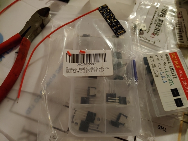
Not sure why you're worried about heat on the LM317, I've never seen one fail from being soldered.  I used to get my lighting boards in without the thru-hole part (the LM317) installed and soldered them in myself.  I never lost one to heat, I think the first 1500 boards were done that way.  Now they're soldered in by the PCB house, but I've still never had a bad LM317.

You're solving problems that don't exist!

John. This way if I don't get a . Fixed voltage I can swap out 317. To see if it is a 317. The 3 boards that don't have a fixed voltage .solder joints look ok. But that's the only other thing that could be causing it. I can't see any solder that may have touched where it shouldn't be.

I use a magnified headset 

I did find a diagram a guy did to test the 317.

Need like 5 different resistors and switches.  Not sure why he didn't use a trim pot.


riki posted:

...

But. R1 holes are a pita...i don't have a drill small enough

If you were messing with a drill bit trying to enlarge a hole there is the possibility the pad's integrity was compromised.  That is, you have the ring on the top and bottom of the board...but there is a conductive column on the wall of the hole.  Yanking tight-fitting resistor thru the hole can also affect the pad's integrity.

As others suggest it's hard to believe you destroyed a LM317 from heat.  Presumably you clipped the 3-terminal LM317 from a non-working board and plugged the suspect LM317 into a known good board with a socket.  I'd think that would be suitable in this case for an LM317 test circuit. 

Riki, Stan has made a good point about damaging the tiny copper sleeves through the board that connect the top and bottom pads, by pulling leads through.

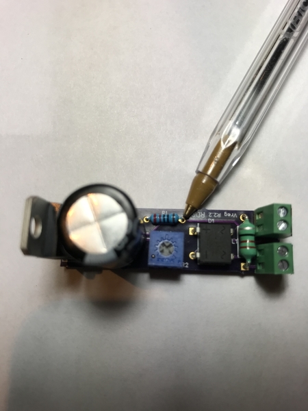
The hole pointed out in this picture:

IMG_0468

is the one that could be affected because it has a connecting trace on the top of the board. Presumably you soldered from the bottom, and its possible this trace is not electrically connected. An easy fix is a dab of solder on the top trace to assure connection. The other end of R1 is not affected because the connecting trace is on the bottom side of the board.

Regardless, the new gerbers that I did up for you have a much larger pattern for R1, with larger holes, so they should work way better. 

Rod

Attachments

Images (1)
  • IMG_0468
Last edited by Rod Stewart

Ok..

I'm 99.9999999999999. Sure it's the voltage regs.

Did resolder . no reg.

Changed 317. Held fixed voltage.

My other boards. The ones that didn't work.. No change there. So got to be voltage regs.

The 317 that I cut. Which is new. Didn't work in either board I made with sockets.

So that. Is  My... Scientific .. Result. That some of the regs are bad.

Riki, I think the test socket is a brilliant idea, thanks for sharing. As I understand it from our offline discussions, you used an 8-dip socket cut in half lengthwise, then cut one pin off, correct?

This would make it easy to build a one-of board for testing various TO-220 and TO-92 packages. One socket would work for 317T and 317L because they have the same pinouts. Then you could have another socket for 78xx and 78Lxx chips, and maybe others? You could also set the board up with an attached digital voltmeter to make that part easy. Hmmmmm, I think I feel another board design looming....

Rod

OK, I admit, I scanned through this thread so I'm uncertain of the details, but I am also floppin' on the dock here.  (fish outta water an all that)

I have an older Lionel caboose, with one pick up, that is blinking over FasTrack switches.  I wanna stop the blink.  What, in 1, 2, 3, etc., steps do I need to do and where do I get the stuff to do it with?

Go...

Add Reply

Post

OGR Publishing, Inc., 1310 Eastside Centre Ct, Suite 6, Mountain Home, AR 72653
800-980-OGRR (6477)
www.ogaugerr.com

×
×
×
×
Link copied to your clipboard.
×
×