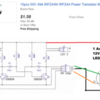
This is a simple little project I have been working on, intended to flash LED's for road crossing flashing lights. The circuit as shown alternately flashes the LED's at about 2 seconds for a complete cycle, which looks about right to me. The cycle length can be lengthened by increasing the values of either C2/C3 or R3/R4. But I would like to be able to adjust the cycle length on the fly without the bother of changing components. I could put individual trimmer pots in place of R3/R4, but is there a simpler way to do this? I know there is a board available at wehonest which includes variable flash speed, but I kind of want to build my own. Thanks for any help.

Rod


Attachments

Original Post

Replies sorted oldest to newest

I don't see a way to modify this circuit easily to change the rates, you have two variables to change to keep the duty-cycle 50/50.

How about a dual-gang 100k pot?  You could add a series resistor of around 47K to adjust from 50K to 150K?  I looked for a smaller trimmer, but dual trimmers apparently don't exist.

Dual-Gang 100K Pot

Attachments

Images (1)
  • mceclip0

If size matters, I'd think that dual-gang trimpot is a tad large and somewhat expensive at 65 cents (that's more than the cost of all the other components).  Presumably this is an infrequent or once-and-done adjustment.  That said, why not use two individual tiny low-cost trimpots for R3 and R4.  Sure, you have to make two adjustments nominally set to the same value.  But this actually can have an advantage in that you can "trim" out any C2 vs. C3 variations to get closer to 50% duty-cycle.

OTOH, if you're only looking for a small trim range, say +/-25%, you could use just one trimpot inserted between the junction of R3-R4 and the positive supply.   If the single trimpot value is similar to or preferably smaller than the value of R3-R4, the circuit should behave.  For example if R3-R4 are 100K, a 50K trimpot should work fine.

Separately, this circuit should exhibit flash-rate dependence based on the voltage.  I notice you have a rather large variation in voltage range.  If you are messing around on the bench and have a variable voltage supply, that might be another way to vary timing without using a trimpot(s) in place of or in conjunction with R3-R4.  For the curious hard-core DIY'ers, at larger voltages this popular design (it seems to keep popping up) has the interesting property of momentarily turning the 2 transistors into Zener diodes across the reverse-biased E-B junction on each alternating flash.  This makes the timing dependent on the DC supply voltage though doing the math would be tedious to say the least!


Hey guys, thanks for all the input. I knew some good ideas would pop up.

I first saw this circuit in a Radio Shack publication by Forrest Mimms, a long time ago, lol. I think he called it a "free running multivibrator" or something like that.

Stan I like the single series trim pot idea. I think I will experiment with 50-100K pots and see what seems to work best. I like  the idea of also being able to compensate for variations in supply voltage. I noticed when breadboarding the circuit that the flash rate was very dependant on voltage. I bet a clever guy like you could whip up an Excel SS to figure out what values of R3/R4 would work with various supply voltages!

Rod

Update: I have been experimenting with the trim pot idea suggested by Stan. With R3/R4 values of 100K, a trim pot of 100K seems to work well. I also reduced the C2/C3 values from 22 uF to 10 uF. All seems to work. Flash rate is about 1 Hz; or 2 seconds per complete cycle. That looks about right to my eye.

Interestingly the flash rate seems unaffected by supply voltage difference, at least over a range of 6-12 vdc. The LED brightness is affected somewhat by trim pot adjustment, but not noticeably so. It is more affected by changes in supply voltage of course. Overall it seems like a good little flasher circuit and I have ordered some test pcb's from OSH Park.

As an aside; has anyone got any ideas on how I might be able to use this basic circuit to alternately flash a couple of large 12 volt LED's, say up to 1 amp load? I have this vague idea that I might be able to use the low power alternating S8050 outputs to drive two larger NPN power transistors, say TIP120's or similar. These are rated at up to 5 amps collector current and 65 watts TDH. But I have no idea is this is doable. Appreciate any thoughts.

Thanks, Rod


At face value it seems like such a simple and low-cost circuit.  But start adding twists and turns and it reminds me of peeling layers of an onion - it will bring tears to your eyes!  So doing an OGR search, there have been many threads about this circuit...such as this one.

In the linked post, the beefier 2N3055 NPN transistor is proposed in place of the S8050.  Now here's where it gets tedious.  For a quick back-of-envelope calculation, a typical transistor might have a current gain of, say, 100.  So if you're trying to switch 1 Amp in the transistor output, you need at least 0.01 Amps (10 mA) at the transistor input.  In your existing schematic you have a 100K resistor at the transistor input.  In addition to charging the capacitor for the cycling function, this resistor must also supply the current to the transistor B (base) input pin.  If you only have 12V DC to start with, going thru a 100K resistor can supply at most 12V/100K = 0.12 mA which is woefully inadequate if you want that transistor switching 1 Amp.

So the idea of separating the circuit into the cycling/alternating portion from the buffering portion (to drive the 1 Amp bulbs) is a good one.  But to be clear, is the objective to use the OSH Park board you ordered as the cycling circuit...and then the question is how to buffer the board output for a one-off higher power version?

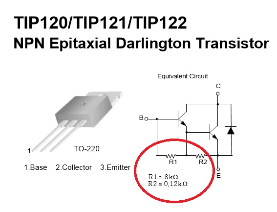
How important is it to use the TIP120?  This is a so-called Darlington NPN transistor which has much higher current gain than a normal transistor so might be applicable.  But is tricky to apply directly in place of the S8050 because of internal resistors that are small (and hence will "overwhelm") compared to your 100K external timing resistor.  This would mess up the capacitor charging.  There are ways around this but more layers of the onion!
tip120


Attachments

Images (1)
  • tip120

Thanks again guys for the input.

Stan, my plan was to use the 8050 outputs from the existing circuit to control the switching of two larger power transistors, to do the heavy lifting. The intent was to retain the 8050's as the basic alternating part of the circuit. Sorry if I did not make that clear. I suggested the TIP 120's only because I have several on hand. They may not be the best choice, I don't know enough about them to make that call. The 2N3055 circuit may work directly, but it's not clear whether it would handle 1 amp loads directly, though I see they are rated at up to 15 amps! Also, TO-3 packages are not nearly as handy to implement as TO-220, IMO. What do you think?

Chuck, thanks for this idea. I'll maybe try and modify my schematic as you have suggested using a TIP42C or ECG50 or some similar medium power PNP type. I have a couple of NSDU56's on hand which come up as a 2 amp PNP TO-202 package with a gain of 80, so they may work, don't know.

Rod


What he said.  As touched upon earlier, the "multivibrator" circuit as implemented can be tricky to adapt to high current (1 Amp) output using a conventional NPN transistor.  FET switches are now cheap.  The N-channel FET used in the MTH DCS TIU often comes up for DIY repair.  I see they are still about 15 cents each on eBay (free shipping from Asia) and are rated for 49 Amps .

The key is FETs have effectively infinite current gain so become what amounts to an "ideal" buffer.

irfz44n

I see you have a 3-pin connector (?) on your OSH Park board.  Simply confirm the L1 and L2 outputs are toggling between ~0V and ~12V.  At a slow enough alternating speed you only need a voltmeter (rather than an oscilloscope) to confirm the full voltage swing.   If not, then increase the 200 ohm resistors (to, say, 1K, 2K, whatever) until the you get a full swing.  Increasing the 200 ohm resistor will dim the on-board LEDs but that's OK - you need the full voltage swing to use the low-cost N-channel FET buffer as proposed.

Attachments

Images (1)
  • irfz44n
Last edited by stan2004

Thanks again Stan and John for this idea. 49 amps; holy smackers! Those should handle things easily. I think I will go ahead and test those mosfet's and see how it goes. Just ordered some, only a few for testing for now. I will do that 0-12-0 volt swing testing on L1/L2 first Stan, and see where that takes me.

John, no I don't need to flash the LED's also. The original basic board with the 8050's will work for the LED flashing task as is. Just wanted to morph the basic board into something that I can use for flashing much larger LED bulbs for another task, so the LED's can surely be eliminated.

Next project will be to revise my schematic and put that up on here for all to critique.  

Thanks, Rod

Rod Stewart posted:

… Stan, on the modified circuit that you did up (3 posts above), are the supply and drain connections to the mosfets shown correctly?

Yes, S (Source) to ground and D (Drain) to the "-" side of the high-current LED.  The "+" side of the LED goes to DC+ supply.  Glossing over the details, for a N-channel FET like this, when you apply a voltage of about 5V (or more) between G and S the FET turns on and "shorts" together the D and S terminals.  By "shorts" this means a low resistance typically measured in fraction of an Ohm for power FETs like this.

BTW.  I believe when the circuit first turns on there might be a delay of a cycle or two until it settles into a steady alternating pattern.  I'd think there might be situations where both LEDs are simultaneously ON or OFF until the capacitors settle into their ping-pong action.  By using the more common and typically less expensive N-channel FET (vs. a P-channel FET), the high power LEDs are inverted from on-board LEDs.  No big deal for a couple low current LEDs...but I'm thinking of both 1 Amp LEDs on momentarily pulling 2 Amps. 

Ok thanks Stan for that explanation and confirmation, just wanted to make sure that I understood. Playing with mosfets is new turf for me, lol.  Once the mosfets I ordered arrive I will test them out and see how they work. Should be very interesting. I will let you know how they behave, particularly during the power up stage!

Meanwhile yesterday I breadboarded another LED flasher circuit using a 555 timer chip, and it seems to work quite well. Quite stable over a wide range of supply voltages. Very easy to set a flash rate anywhere from about 3 or 4 Hz down to slower than about 1/2 Hz. I presume that mosfets could also be used with this type of circuit?

Thanks, Rod

Last edited by Rod Stewart

Add Reply

Post

OGR Publishing, Inc., 1310 Eastside Centre Ct, Suite 6, Mountain Home, AR 72653
800-980-OGRR (6477)
www.ogaugerr.com

×
×
×
×
Link copied to your clipboard.
×
×