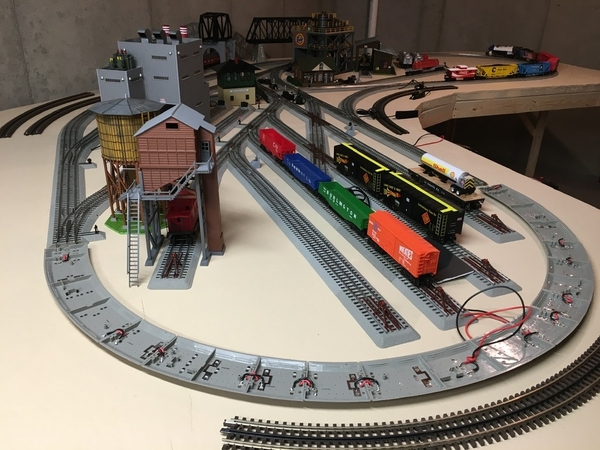
Hi Forum friends. My layout is effectively a 18 x 15 floor layout, so drop connections from the track to a buss running below are not possible. I must rely on a limited number of connections (every 7-8’) to a 16-awg perimeter buss carrying track voltage. I find Fastrack to be very, very unreliable, especially in terms of center rail connection continuity.

My question is, how could I bridge the gaps between track pieces to guarantee continuity of center rail voltage? Could I solder a small piece of unstranded wire across the track gaps? Can you even solder to the sides of the aluminum rails? Is there something like a small flat piece of metal which I could use with conductive adhesive to adhere to the rails over the gaps? This needs to be something I can do from the top of the track, preferably. Any ideas and thoughts would be much appreciated!

David Ogletree
Needham, MA

Original Post

Replies sorted oldest to newest

They are not aluminum rails and you can solder to them no problem ..I have fastrak and have no issues for most part..I take small visegrips at the joint and squeeze a lil on both sides of joint ..i do have drops but thats really only for voltage drop..message me and ill talk you thru what i do..Im a MA guy also

Last edited by Snkbittin

Hi David,

Not a top side solution, but maybe you could separate your layout into some portable sections - flip each section over and solder jumpers between the pieces.  Like this end loop section of my layout, electrically now a single piece of track.  Long straights would be another candidate.

Mick

12x12 L - Solder connections for Fastrack compound O44.5 curve sections

Attachments

Images (1)
  • 12x12 L - Solder connections for Fastrack compound O44.5 curve sections
@Mick60 posted:

Hi David,

Not a top side solution, but maybe you could separate your layout into some portable sections - flip each section over and solder jumpers between the pieces.  Like this end loop section of my layout, electrically now a single piece of track.  Long straights would be another candidate.

Mick

12x12 L - Solder connections for Fastrack compound O44.5 curve sections

Did the same thing for our Polar Express Christmas layout.  Works really well without fiddling with individual small section connection issues.

Thanks for your help guys. I think the jumpers soldered between pieces is the best way for me to go. I didn't realize that the pads were designed to be soldered to underneath. I thought only the terminals for wires connections were available. I'll get myself a good solder gun with medium and high wattage settings and that should do the trick nicely I suspect. It's been a frustrating time trying to keep the trains running smoothly, especially since my layout is unfortunately in a non-climate controlled space in my attic and the big temperature swings wreak havoc on the interconnections - even with the tracks screwed down!

Thanks for your help guys. I think the jumpers soldered between pieces is the best way for me to go. I didn't realize that the pads were designed to be soldered to underneath. I thought only the terminals for wires connections were available. I'll get myself a good solder gun with medium and high wattage settings and that should do the trick nicely I suspect. It's been a frustrating time trying to keep the trains running smoothly, especially since my layout is unfortunately in a non-climate controlled space in my attic and the big temperature swings wreak havoc on the interconnections - even with the tracks screwed down!

Hi David,

Soldering each piece of FT to the next will certainly make your track connections and connectivity virtually bullet-proof, but it is a laborious process, depending on how many linear feet of track you have and whether you are using any 30" straight pieces.

Both the center (+) rail and one outside rail (-) can be linked together along the entire perimeter, if necessary. I would use stranded 14 gauge wire. You can also create small "tunnels" in the underside of the FT for the wires to pass through, with a rotary sanding disc and a Dremel type tool.

Rather than do the entire layout, you might want to first check all along the layout with a digital voltmeter ("DVM"); then apply the above manual fix; and see if that solves the problem. If not, you can then use the solder method for just those sections where there are voltage drops. I have done that to certain problematic sections of my FT layout.

Even if all the sections are soldered together, that does not necessarily solve any voltage loss issues resulting from not enough power drops alone the layout. Even layouts with perfect connectivity may still need multiple power drops.

We touched base many months ago and live on the North Shore and have relatives in the Needham area and would be glad to stop by and try and help out, but my availability in the next couple of weeks is limited.

Last edited by Richie C.

Add Reply

Post
The Track Planning and Layout Design Forum is sponsored by

AN OGR FORUM CHARTER SPONSOR

OGR Publishing, Inc., 1310 Eastside Centre Ct, Suite 6, Mountain Home, AR 72653
800-980-OGRR (6477)
www.ogaugerr.com

×
×
×
×
Link copied to your clipboard.
×
×