
Hello everyone, I'm new to the forum - thought I might find the help I need here.

I've recently started assembling a vintage General Models Corporation Pacific, which uses the same mechanism as the All-Nation locomotives. So, here's my problem... When I try to install the "bearing plate" (the plate that mounts underneath the frame and retains the drivers), the second and third drivers begin to bind up. This is just with the screws finger tight. Is there a known solution to this?

Last edited by Johnbeere
Original Post

Replies sorted oldest to newest

Is in possible the bearings have a flat side, that should be down against the plate, while the rest is in the slot.   I built an AN 4-4-0 years ago and did not have any issues like this.  

Another solution if there is not enough height for the axles is to file the top of the slot in the frame to gain a few thousandths.    And I would suggest bolting the two frame halves together and filing both sides at the same time to keep them as much the same as possible.

Yeah, it's definitely hitting the bearings on mine. Maybe someone could look at their All-Nation locomotive for me and see if it does clamp on the frame? The slots for the bearings may not be milled deep enough on my locomotive. It would be really appreciated if someone could measure how deep those slots go for them so I know for sure that's my issue.

It's hard to take pictures of this - there's not really any good angles. The last photo I posted shows the locomotive upside down, looking between the frame and plate to show how much the bearings protrude.

I think you may be missing some sort of spacer piece that goes between the plate and the frame. There are four holes in the mounting plate that go into the cross-members. The plate has three additional holes. For what are they used? Do the holes in the plate align with the holes in the cross-members? If the motor is mounted to the top of the plate, the plate height may be critical for proper engagement of the motor worm gear to the spur gear. It may be possible to put three washers between the plate and the cross-members. The front cross-member is at a different height and looks like it needs a longer screw. Are there drawings in the instructions?

MELGAR

Last edited by MELGAR

Something is not right. Is the frame assembled perfectly square? Do the bearings fit snugly or tightly into the frame slots? They should not be free to rotate within the frame. Your original complaint was that installing the plate caused the drivers to bind, even without fully tightening the screws. It's hard to believe that slight tightening of the four mounting screws squeezed the bearings enough to cause binding. Are there spacers in the kit?

MELGAR

Last edited by MELGAR

Yes, the frame is as perfectly square as I could get it - in my troubleshooting I held a straight edge to both sides and got it as close to square as possible. The bearings are a loose fit in the frame, until the plate is lightly tightened on. All the axles spin freely in their bearings - with the plate removed, and rotating the wheels by hand, the bearings aren't turning. The kit did come with two sets of two different kinds of spacers - I'm not sure what they're for, but since they're not shown or specified to be used for this purpose, I don't think they're to be used here.

My thought of what is actually happening is that the bearings might be twisting a little in the frame when the plate is tightened on them.

It's possible that spacers go between the cross members and the plate to introduce a gap between the plate and the frame. (The longer spacer might go onto the front cross-member.) The other possibility would be to have a flat spot on the bearings. You would have to be certain before you file the bearings that you would not have to file so deeply into the bearings that you get to the axle bores.

MELGAR

Last edited by MELGAR

Do you have a dial calipers that you can use to measure the depth of each slot (all 6)? If so, is the measurement the same for all 6? If you sight down the frame, or put a straight edge on the bearings, are they all at the same height/depth? If only 2 axles are binding, that suggests they are not all seated to the same depth in the frame.

Chris

LVHR

They all appear to be at the same depth - Owing to my theory that the bearings are getting slightly out of line when they're pressed on by the plate, it's probably just luck that the first driver spins freely. Hopefully someone with one of these old locomotives can report back to me with what's different about my locomotive. I'm fairly confident flat spots on the bearings will fix it, but I want to be really sure that that's what needs to be done before I do that.

@Johnbeere posted:

...They have a smaller diameter section in the middle, and a larger diameter section on the ends. I think if I file just far enough to where the file starts touching the smaller diameter, I'll be okay.

If you're referring to the outside diameter of the middle bearing section (end-middle-end), that should be OK. There might be some way of mounting the bearings on a rod or between the jaws of a vice (with protection from the jaws) so that you can get an aligned flat surface with the file. The better way to do this would be at a machine shop but may not be necessary.

MELGAR

Last edited by MELGAR

When I built this All Nation model back in 1970, I had the same problem.  The drive bearings have  an external groove  which allows them to fit into the frame slot.  Two had a snug fit, so I made sure they were both on the same axle. I then filed both sides of the axle slot in the frame slightly, until the bearings were a slip-in fit.

When putting on the retainer plate, I found that it touched the rims of all four driver bearings but did not touch the frame by a few thousanths of an inch.  So I filed the rims of each bearing until they matched the frame's bottom edge. Not much had to be removed, but it allowed the retainer plate to firmly fit on the frame with no binding of the drivers.  I did not want to file the axle bearing  slots deeper, as that would lower the locomotive closer to the rails and possible cause the pilot to touch on uneven track or beginning to climb a grade.

Fitting the worm to properly mesh with the main driver's gear required some fussy fitting of shims under the heavy brass mount to get it just right.   A half century later, it still runs great!  I sold it in 2018. Here it is at its new home.BO1447b

S. Islander

Attachments

Images (1)
  • BO1447b: All Nation kit No. 5, built 1970. Re-built as a B&O A-3 in 1988. Constant / directional headlight, on-board synchronized sound unit.
Last edited by S. Islander

Two things that occur to me.   First in the photo of the mech with bottom plate off, it looks to me that there are flat spots on some of the bearings.    Maybe this is an optical (obstacle) illusion?

The second thing is it looks like the side  rods are already attached to the drivers.    The bind may be in the rods not the bearings.     I have a friend who has one of these and I asked him about it.   He said his base plate does not fit tight to the frame either, but his drivers turn freely.    He did not think tightening the base plate could deform the bearings easily.    So my suggestion is to remove the side rods and try installing the drivers and see if they turn freely.    then add side rods one at a time and see which one binds, if it is a rod bind. 

The other idea mentioned above is that the bearings do not slide all the way up into the frame because the flange  way on the bearings is too narrow.   That may be something to look at also.

I have never built one these models.  However looking at your pictures and instructions sheet, I am wondering if the bearings are backwards.  It looks like in your top view picture the part of the bearing outside the frame is thinner and not as high.  The instructions show a large diameter on the outside of frame.   I am an expert, but from the pictures the part of bearing outside the frame looks smaller.   Good luck. 

Thanks for all the help. Good to hear I'm not the only one who has had a similar issue to this, and that filing the bearings fixed it - going to hold off on filing them until I'm sure that's what I want to do.

Since the wheels were binding before I installed the rods, I don't think the rods are an issue. Plus, it all rolls very smoothly with the plate removed.

Looking at the bearings, both ends look like they're the same diameter, and I'm confident that there are no flat spots on any of them.

Thanks for the input, sounds like filing them might be my best bet. I'll probably wait for another day or so before I go ahead with it in case someone comes up with a better solution.

In the mean time, does anyone have instructions for the boiler and tender? I only have the instructions for the mechanism.

I'm also missing three parts so far - the two "piston rod bushings", part 1382, and one of the screws that attach the eccentric rod to the eccentric (I've currently got a different screw in place of it, but having the correct screw would be very nice). If anyone has a parts locomotive, I would really appreciate buying those parts off you.

The bearings are actually square instead of round? Hmm, interesting. Okay, good to know that the plate should be clamping on the frame for sure.

So, my current options that I see are:

1. File a flat face on the bearings, or 2. File the slots for the bearings deeper.

Filing a flat face on them seems like the way to go - I'll wait to hear what you find on your 4-4-0 though, I'm not in a big rush to do this.

It's the right thing to do.  Even if it is wrong, you are not destroying the bearings.  They still have 270 degree flanges, and you can rotate them up.

I admit to never following instructions - most of my A-N locomotives are seriously modified - and only two have the original B&O drivers.  The rest have Lobaugh, and most have new frames with individual pedestal binders.

Those modified ones sound neat, feel free to post photos, I wouldn't mind seeing what these kits can look like with modifications.

In my case, I probably won't be modifying this locomotive much at all - I like the old-school nature of this kit, so I'll retain the originality of it. Only thing I think I'll do is change out the tender trucks - I have a nice pair of Auel Super-Detailed trucks (with working journal box lids) that may look good with this locomotive.

Thanks for the help everyone! Now, after filing a flat spot on all the bearings, the plate is able to clamp down on the frame without binding any of the drivers, and it's rolling smoothly.

Now onto my next issues, I think I mentioned these before:

I don't have instructions for the boiler or tender sections of the locomotive. Maybe someone could photograph their instructions for me? That would be really appreciated.

Neither of these parts are critical, but I'm missing both piston rod bushings and one of the screws that attaches the eccentric rod to the eccentric crank (I currently have a different screw in its place). Does anyone have a parts locomotive that I might be able to get those parts from?

I know, I'm not too worried about any of those parts, but owing to my goal of originality, having the correct parts would be quite nice. I've already found a screw to replace the one for the eccentric rod, though I'd still like to replace it with a correct original.

There's no rush to these, since none of these parts are critical.

@Johnbeere posted:

Thanks! I would be happy with just legible pictures of all the pages, but if you'd like to send me a copy that would be even better.

So... How do I send DMs? I haven't fully learned how to do everything on here yet.

I think if you go to my profile page, you can get my email address there... I'll keep an eye out in case your message goes into my spam folder...

Mark in Oregon

While waiting for the instructions, I've been thinking about what locomotive I should letter this as. Probably a USRA Light Pacific, since it roughly is one. One candidate I've thought of is the ACL 1504, which stands out to me as I've seen it in person. There are definitely detail differences though - the pilot and trailing truck, the Engineer's side running boards, etc., so it's not a perfect match without changing details - which in this case I don't want to do.

But then, I was thinking... Maybe the tender could be lettered "General Models Corporation". I think that might be neat, considering especially that there really is no real life prototype to this, and it's simply a creation of General Models. That doesn't solve what number I'd use though. Any ideas on how I might make/acquire custom decals like that?

@Johnbeere posted:

While waiting for the instructions, I've been thinking about what locomotive I should letter this as. Probably a USRA Light Pacific, since it roughly is one.

When I applied for Social Security, there was a question on the form if I worked for "the railroad."  Not "a" railroad, but "the" railroad.  As if there was only one railroad in the US.

I found this amusing, so here is my solution to your quandary:

4-6-2 TR 1313

Rusty

Attachments

Images (1)
  • 4-6-2 TR 1313
Last edited by Rusty Traque
@Johnbeere posted:

While waiting for the instructions, I've been thinking about what locomotive I should letter this as. Probably a USRA Light Pacific, since it roughly is one. One candidate I've thought of is the ACL 1504, which stands out to me as I've seen it in person. There are definitely detail differences though - the pilot and trailing truck, the Engineer's side running boards, etc., so it's not a perfect match without changing details - which in this case I don't want to do.

But then, I was thinking... Maybe the tender could be lettered "General Models Corporation". I think that might be neat, considering especially that there really is no real life prototype to this, and it's simply a creation of General Models. That doesn't solve what number I'd use though. Any ideas on how I might make/acquire custom decals like that?

It reminds me a little bit of the WM 200 class, if you omit the steps to the running boards.

Hmm, there's some similarities to that one, but I think it's much closer to a USRA Light Pacific. Probably not going to really find anything it's closer to, since it was made as a very generic design. I wonder why General Models didn't model a more specific locomotive - maybe they thought if it was generic it could be made to represent other engines? Kind of a strange decision.

I actually really like the idea of lettering it as "General Models Corporation", but that's going to require decals to be made for it. Not sure how I can go about that.

Last edited by Johnbeere
@Johnbeere posted:

Hmm, there's some similarities to that one, but I think it's much closer to a USRA Light Pacific. Probably not going to really find anything it's closer to, since it was made as a very generic design. I wonder why General Models didn't model a more specific locomotive - maybe they thought if it was generic it could be made to represent other engines? Kind of a strange decision.

I actually really like the idea of lettering it as "General Models Corporation", but that's going to require decals to be made for it. Not sure how I can go about that.

Gee, with that fat boiler, to my mind the GM model looks kinda like a heavy(er) Pacific...

In any case, I will be mailing you those instructions later today. 

Mark in Oregon

I think it's the domes that make it look closer to a light pacific that a heavy pacific - the heavy pacifics have more squashed domes. Also, the photos in the instructions show a smaller tender than these normally came with (or at least the one mine came with) - I think the small tender makes the boiler look bigger than it is.

Thanks again for those instructions - I'd be lost without them.

The instructions came in today, thanks @Strummer!

It seems that the second section requires more special taps and drills - I'll be ordering them soon.

In the mean time, I've been slowly cleaning up the boiler casting with files and sand paper - it's turning out nicely.

Strangely, I don't see where in the instructions it details how you mount the backhead. Is it soldered on?

Here's some pictures of where I'm at:

I like how realistic the valve gear is, although it was quite a fiddly job to set the rivets. My kit actually came with 4 extra rivets.

I decided to mount an old scale operating coupler on it, and set up to open when the bar is pulled. (I can't seem to remember the proper terminology for that bar...)

The boiler sitting on the frame, I still have more filing to do before it sits properly on the steam chest saddle. Currently, the front of the boiler is resting its weight on the steps, instead of the steam chest.

The back of the motor slightly sticks out from the back of the boiler, this is going to be a big issue later when I need to attach the backhead. Any ideas?

Attachments

Images (5)
  • mceclip0
  • mceclip1
  • mceclip2
  • mceclip3
  • mceclip4

So, I've tried moving the motor forward, and managed to move it a little bit... But not enough. It's sticking out about 1/32 of an inch... So close. I'll try for a bit longer to see if I can get it to move any more forward.

Edit:

I'll add that what I had to do was to tighten the curve of the motor mounting bracket by holding it with a vice and flattening the curve with a hammer. It tightened just enough to move the motor in some.

Last edited by Johnbeere

A bit of an update... I've been working on trying to fit the boiler to the chassis, and have the boiler level and upright. This has been more challenging than it ought to be.

I needed to lower the motor so that the boiler could sit lower, and to do that I had to use some washers under the front of the motor bracket in order to raise the front, so I could lower the motor without changing the mesh of the worm gear. This turned out well, except the motor now sticks out of the firebox again, and I don't think it's fixable this time. I may be able to use a dremel to cut a cavity out of the backhead to give just enough clearance for it to be mounted.

I've also had to do a lot of filing to get the smokebox to sit down properly on the steam chest, and now I'm finding out that the mounting hole in the bottom of the boiler may be ever so slightly offset, which causes the boiler to lean a bit when tightened. I may need to fill that hole by soldering a screw into it and re-drilling the hole, but I'm not confident in my ability to get it perfect. Maybe I can rely on the cab to hold the boiler straight up and down while drilling the new hole, using the hole through the steam chest as a guide for the drill bit.

So today I tackled a couple of the soldering jobs I had to do. Soldering definitely isn't my strong suit, but it went okay.

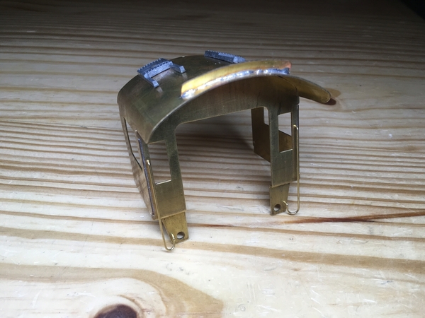
First, I soldered together the cab - I needed to solder on the handrails, solder the back of the cab on, and solder the smoke deflector on. It turned out pretty well, here's what it looks like:

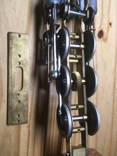
I also needed to dismantle the trailing truck and resolder it, as it was assembled very crooked when I got it. My soldering iron couldn't melt all the solder at once, so I took it outside and got it apart with a torch. I took this as an opportunity to clean the trailing truck wheels, as they were a little rusty - most of the rust came off after soaking the wheels in some Simple Green. (I'm not sure why the Simple Green worked that well to get the rust off, but most of it came off after a short soaking. It was just surface rust, though.) I then soldered the trailing truck back together, my first attempt didn't go well - the solder joint broke after cleaning up the solder with a file, I don't think it was deep enough into the joint. Anyway, I soldered it back a second time, this time taking more care to get solder into the joint, and it's holding well now.

Attachments

Images (1)
  • mceclip0

You have the skills.  Just consider this a learning experience, and soon you will be building your own.

Plug and redrill.  Don't try to drill on assembly; just measure and get the hole dead center on the bottom.

extend the backhead further aft with a brass spacer.  Many steam locomotives had the backhead almost even with the rear cab bulkhead.  You won't have to go that far - an eighth of an inch of brass, and some putty . . .

I don't really have the stock or tools to make the spacer, so it seems much easier to me to just create a groove in the backhead. The backhead is about 1/8 thick, I need to make the groove about 1/16 deep, which isn't too bad.

The instructions say that I should screw the backhead on, but there aren't any good positions for screws - I'm thinking that I'll ultimately try to solder it on.

Well, what you don't see is before I smoothed it out with a lot of filing... The solder was cooling down very quickly so it globbed up, even with my soldering iron as hot as it could go. I definitely have a lot left to learn when it comes to soldering. What I am pretty good with, though, is filing it down so you can't see the mess.

Another update, I've been busy lately, but finally got around to do some more soldering jobs I wanted to do. First off, I got the screw hole in the smokebox filled, in preparations for re-drilling it. I'm very new to soldering with a torch rather than an iron, but it went well and the solder seemed to flow into the joint nicely.

I also decided that I needed to resolder the backhead properly, with a torch this time. I wasn't happy with the big blobs that the solder had formed on the first attempt, rather than properly flowing into the joint. Unfortunately, this means that the backhead ultimately ended up moving a little, so I have more filing work to smooth it out again, but it won't take as long as last time. It turned out much nicer this go around, since I had enough heat to create a much better joint.

I'll continue to give updates as I get work done on it - I've been busy lately so I'm not sure how often that will be.

So, I haven't done much to the locomotive recently. While trying to tap a hole for one of the boiler front screws, the tiny 0-80 tap broke off into the hole, and I left it like that. Well, today I finally got the tap out and the hole filled to do it again... And I broke another tap. I probably twisted it too hard, but I was struggling to figure out why it was binding up. While tapping it, I periodically cleared the chips and even passed my drill bit through the hole each time I cleared the chips, as I thought that may help. I also lubricated the tap... Yet it still broke. Before I break a third tap (after buying replacements for my broken two), any ideas why I might be struggling on this? It entered the hole without issue, but it started to get harder once it was about 2/3 through.

What kind of tap?  Greenfield, or a four dollar hobby tap?

Drill the hole all the way through, and you stand a chance of driving the broken part out the bottom.

Also, a #55 drill will give you plenty of threads, yet allow easier tapping.

Ten years ago, a good tap was eight bucks.  Mine break after several hundred holes, and I buy them three at a time.  Have no idea what a good tap costs now.

I got the taps from McMaster - I think they were about ten bucks each. I don't have a #55 drill, so I used the closest I had, which was a #57. However, I don't think that's my issue, since the tap happily threaded the first half of the hole. This hole goes all the way through, and exits sort of halfway into the wall of the casting - so maybe when I drilled it the bit deflected? But I'm not sure that's my issue, since the tap wasn't yet exiting the hole. Admittedly, I'm fairly new to tapping holes, this kit is the first time I've actually had to buy taps, so I may be doing something wrong without realizing it.

What taps do you recommend, and where do you buy them?

Yes - I use a Dremel cutoff disc and a magnifying lamp.  I then test on a scrap to see two spirals before using it on anything valuable.

Yes - a #57 drill simply causes tap breakage.  Never use a drill smaller than recommended, no matter the size.  Henry Pearce told me he always used one size larger, and his kits are still bulletproof.

Some cutting fluids are better than others - the little yellow can from Ace is ok.  Never tap dry, and never use just plain oil.

It's been quite some time since I did any work on the locomotive, but I've finally done some more.

I really didn't like the floor that was cast as part of the backhead, so I decided to make my own floor out of a sheet of brass, and solder it into place. I then removed the old floor by cutting it off with a Dremel tool and then finally filing it into shape to keep the piping detail intact.

This locomotive has a habit of fighting me every step of the way - I realized one of the holes for the pins that mount the cab was drilled in the wrong place, so I had to fill and re-drill it. That's at least the third or fourth hole I've had to do that for.

mceclip0

I also decided to add a handrail on either side of the cab and on the sand dome, based on details found on ACL 1504.

mceclip1mceclip2mceclip3

Attachments

Images (4)
  • mceclip0
  • mceclip1
  • mceclip2
  • mceclip3

Add Reply

Post

OGR Publishing, Inc., 1310 Eastside Centre Ct, Suite 6, Mountain Home, AR 72653
800-980-OGRR (6477)
www.ogaugerr.com

×
×
×
×
Link copied to your clipboard.
×
×